Effect of Dislocation Density on the Initiation
of Plastic Deformation on Fe
C Steels
Kaoru Sekido
1,2,+1, Takahito Ohmura
2,+2, Toru Hara
2and Kaneaki Tsuzaki
1,21Doctoral Program in Materials Science and Engineering, University of Tsukuba, Tsukuba 305-0047, Japan 2National Institute for Materials Science, Tsukuba 305-0047, Japan
The effect of pre-existing dislocations and interstitial carbon on the initiation of plastic deformation in interstitial free (IF) steel and ultra low carbon (ULC) steel were investigated by the nanoindentation technique. The critical load,Pc, of the pop-in phenomenon, which corresponds
to plasticity initiation, appeared clearly on the loading curve. ThePcin high dislocation density materials was smaller than that in low dislocation
density materials with no difference between IF and ULC while thePcin low dislocation density materials was remarkably higher in ULC than
in IF. These results indicate that the interstitial carbon in the matrix does not affect the pop-in phenomenon when there are pre-existing dislocations or dislocation sources, and we discuss the reason for their occurrence occurs in high dislocation density materials.
[doi:10.2320/matertrans.M2011356]
(Received November 21, 2011; Accepted February 6, 2012; Published March 28, 2012)
Keywords: plasticity initiation, dislocation density, nanoindentation, steel, carbon
1. Introduction
Nanoindentation is a valuable tool for studying the fundamental aspects of plasticity on a small scale such as dislocation nucleation.17) One of the characteristics of nanoindentation is the detection of the pop-in behavior which appears as a strain burst on the loading curve. One of the main mechanisms of this behavior is the initiation of plastic deformation such as dislocation nucleation and multiplication.4,8) Plastic deformation of metal results in an
increase in dislocation density, which should affect the pop-in behavior. Wang et al.9)reported that the pop-in behavior of
Ni3Al crystals during plastic deformation was found to
be closely related to their crystal orientation, pre-existing dislocation density in the sample surface, the loading rate, and the holding time. The major pop-ins may be correlated with the special dislocation structure of the KearWilsdorf (K-W) locks in the Ni3Al crystal that are formed during the
loading process. Zbib et al.10) reported that the onset of plasticity of a tungsten single crystal during nanoindentation depends on the pre-existing dislocation density. They showed that it is possible to generate a sudden transition from an elastic to a plastic deformation during nanoindentation even with substantial dislocation densities. Therefore, the dis-location activation models may be more appropriate for many materials rather than those that are based solely on the homogeneous nucleation of a dislocation. Barnoushet al.11)
reported the effect of dislocation density on the pop-in behavior using electron channeling contrast imaging (ECCI) in aluminum alloys. They demonstrated that only a very low dislocation density is necessary for observing the pop-in, and at a high dislocation density the dislocation sources become activated instead of dislocation nucleation. In the present paper, we discuss the effect of carbon on the relationship between the dislocation density and the pop-in phenomena since interstitial carbon is an important element of steel. In a previous report, we discussed the effect of interstitial carbon
on the pop-in behavior in steel with low dislocation density and showed that the average Pc where the pop-in occurs
in ultra low carbon (ULC) steel was higher than that in interstitial free (IF) steel with no in-solution carbon.12)This paper describes the difference in the pop-in behavior of steels with low and high dislocation densities and the effect of carbon on the movement of pre-existing dislocation.
2. Experimental Procedure
The chemical compositions of the IF and ULC used in this study are shown in Table 1. The steel ingots were hot-rolled in a temperature range of 1423 and 1243 K to 3.6 mm sheets. The ULC sheets were cooled to room temperature at 50 K/s, while the IF sheets were held at 973 K to produce TiC carbide particles and then cooled to room temperature. Note that the C content is 0.0158 at%in IF and 0.0734 at%in Ti, and the Ti content is large enough to consume C by forming TiC. The hot-rolled sheets were then cold-rolled to 1 mm thickness and annealed at 1073 K for 60 s to obtain a fully recrystallized structure. To obtain high dislocation density samples, the recrystallized samples were tensile deformed till fracture at around 40% strain by a tensile load at room temperature, resulting in a dislocation density of 1014m¹2. To obtain low
dislocation density samples, the recrystallized samples were further annealed at 1123 K for 7.2 ks and then held at 973 K for 1.8 ks followed by cooling to room temperature in air. The additional annealing produced samples with a low dislocation density of 1011m¹2 which was lower than the dislocation
[image:1.595.304.550.741.786.2]density of 1012m¹2 before the tensile deformation and determined to more appropriate for the purpose of this study. Using the above procedure, we obtained four samples with different dislocation densities for the two steels. The samples
Table 1 Chemical compositions (mass%) of IF and ULC.
C Si Mn P S Al Ti N Fe
IF 0.0034 0.009 0.1 0.002 0.0031 0.034 0.063 0.0016 Bal.
ULC 0.0038 0.009 0.1 0.003 0.0031 0.032 0.002 0.0015 Bal.
+1Graduate Student, University of Tsukuba
+2Corresponding author, E-mail: ohmura.takahito@nims.go.jp
for nanoindentation were mechanically polished, and sub-sequently electropolished in a solution of 8%perchloric acid, 10% butylcellosolve, 60% ethanol, and 22% water at 273 K under a potential of 40 V to remove the damaged layer. Nanoindentation experiments were carried out using a Hysitron Triboindenter. The indentation tests were conducted under the load controlled condition with a maximum load of 1500 µN for the annealed samples and 1000 µN for the tensile deformed samples. A Berkovich indenter was employed, and the tip truncation was calibrated using a reference specimen of fused silica. Analyses for the tip calibration and the calculation of hardness were conducted using the Oliver and Pharr method.13) The probed sites
and indent configurations on the specimen surfaces were confirmed before and after the indentation measurements with the scanning probe microscope (SPM) capabilities of a Triboindenter. The indentation was made on several grains and that were quite far from the grain boundaries and other indent marks. The effect of crystallographic orientation was examined, and the results showed that the grain orientation did not have much effect on the pop-in phenomenon allowing us to choose grains randomly for this study. The tensile test specimens had a gauge length of 50 mm and a thickness of 1 mm which conformed to the JIS-5 standard. The loading axis for the tensile tests was set parallel to the rolling direction. The tensile tests were carried out with an AG-50kNG (Shimadzu Corporation) under a nominal strain rate of 2.8©10¹4s¹1 at room temperature. The dislocation
densities were measured by the Scanning Transmission Electron Microscopy (STEM). The samples for STEM observations were mechanically thinned to 100 µm, and perforated by a twin-jet electropolisher, and the observation was conducted on a JEOL-2010F operated at 200 kV. The dislocation density was determined by measuring the total length of dislocations on the STEM images under the assumption of a 100 nm foil thickness.
3. Results and Discussion
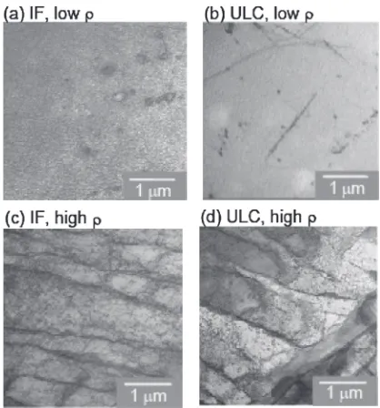
STEM images in Fig. 1 show typical dislocation structures of fully-annealed and heavily deformed samples. The low dislocation density steels show an inhomogeneous disloca-tion structure, and the density was measured in an area with relatively high dislocation density. The dislocation density of the tensile deformed sample was estimated from the inside of the cell structure. The estimated dislocation densities of the annealed and the deformed samples were in the order of 1011and 1014m¹2, respectively, for both steels.
Figures 2(a) and 2(b) show the SPM images after indentation for IF with low and high dislocation density, respectively. The indent mark is around 1 µm. Some precipitates of around 200 nm appear in the SPM images which may be TiC since we found the TiC to be 100200 nm with STEM and EDS in the previous paper.12) The figure shows that the indentation was clearly made in an area with a sufficiently smooth sample surface without any effects from the grain boundary or the precipitates.
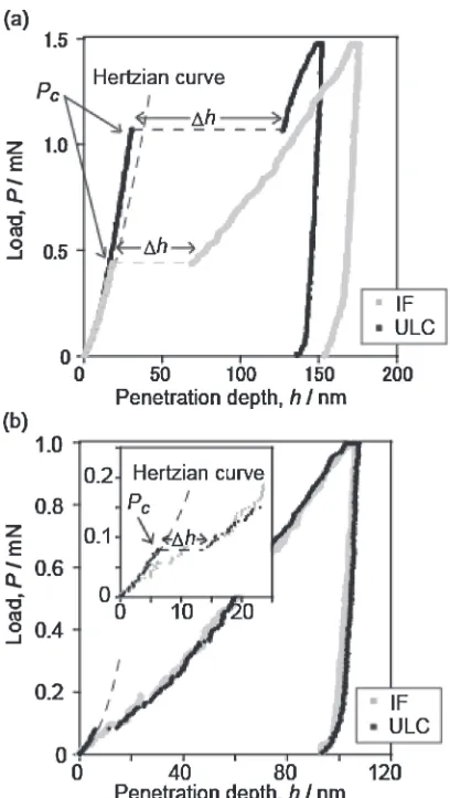
Figure 3 shows the typical load-displacement curves obtained by nanoindentation. Figures 3(a) and 3(b) represent the curves for the steels with low dislocation density and high
dislocation density, respectively. A clear pop-in behavior appears in the low dislocation density steels in Fig. 3(a), and the critical load for the pop-in in ULC is higher than that in the IF. On the other hand, the pop-in behavior is not clear in steels with high dislocation density shown in Fig. 3(b). To make sure a transition in deformation mode from elastic to elastoplastic and obtain the critical load for the initiation of plastic deformation, we used the Hertz contact theory.14)
It was applied to the first point where a deviation appeared on the Ph curve in Fig. 3(b). The load P and penetration depthh are given by the following equations:
P¼43ERi1
2h32; ð1Þ
1
E ¼
ð1vs2Þ
Es þ
ð1vi2Þ
Ei ; ð2Þ
whereRiis the curvature of an indenter tip,E*is the reduced
modulus deduced from eq. (2), vs and vi are the Poisson’s
ratios of the specimen and the indenter, andEsandEiare the
Young’s moduli of the specimen and the indenter. ThePh
curves that were obtained by substituting 200 GPa forE*and 230 nm for Ri into eq. (1) are shown as a broken line in
Fig. 3. The E* is estimated from the unloading curve in Fig. 3, and Ri is determined by measuring a standard
Fig. 1 STEM images for IF and ULC with (a),(b) low dislocation density and (c),(d) high dislocation density.
[image:2.595.322.531.68.292.2] [image:2.595.339.513.343.440.2]sample.15)The calculated curves roughly fit in the data that was obtained experimentally before the pop-in phenomenon in all the materials, which confirms that the pop-in phenomenon in the present study corresponds to the plasticity initiation. Even though the pop-in phenomenon is not clear in Fig. 3(b), the critical load for the pop-in can be found using the Hertz contact curve by considering it as a deviation from the broken line. The critical load Pc at which the pop-in
occurs and the corresponding excursion depth"hare defined in Fig. 3. According to thefigure, thefirst pop-in appears at a lower Pc with a high dislocation density than with a low
dislocation density. This tendency agrees with the report by Barnoushet al.in which Al with high dislocation density did not exhibit a pop-in while Al with low dislocation density showed a clear pop-in.11)
Figures 4(a) to 4(d) are the plots of Pcvs. "h for IF and
ULC with low and high dislocation density. The following things can be determined from thesefigures. First, the average
Pc in the ULC is higher than that in the IF with low
dislocation density. Second, the averagePcin high dislocation
density materials is lower than that in low dislocation density materials. Third, the average Pc in the ULC is almost the
same as that in the IF with high dislocation density. Leipner et al.16) described the critical stress ¸
n for the
dislocation nucleation in GaAs using nanoindentation. They proposed the equation:
¸n¼³Gbe3r 0
2¯
1¯; ð3Þ
whereGis the shear modulus,eis the Euler number,bis the magnitude of the burgers vector, r0 is the cutoff radius at
the dislocation core, and ¯ is Poisson’s ratio. We obtained
¸nµ9.7 GPa using the typical values of r0=b/3, b=
0.29 nm, G=83 GPa, and ¯=0.3 for ferrite. On the other hand, the maximum shear stress¸maxunderneath the indenter
can also be determined from the Hertz contact theory14)as:
¸max¼0:18 E
Ri
2 3
P13: ð4Þ
Table 2 shows the calculated ¸max values for each material,
which was obtained by substituting the value of E*=
200 GPa, and Ri=230 nm, and P with the maximum Pc
value from Fig. 4 into eq. (4).¸maxin low dislocation density
materials is larger than ¸n, suggesting that dislocation
nucleation can occur. The fact that these ¸max values are
close to the ideal strength also supports the occurrence of dislocation nucleation. In high dislocation density materials,
¸max is lower than ¸n, indicating that the plasticity initiation
does not depend on dislocation nucleation but on another mechanism with a lower critical stress.
The reason that the ULC has a higherPcthan the IF in low
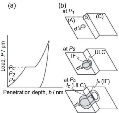
dislocation density materials was already discussed in the previous paper.12)Since there are no dislocations beneath the indenter, a dislocation loop nucleates once an indent is made. We used the model that is based on a FrankRead source generated by a double cross slip. Three load levels indicated as P1, P2, andPcare shown in Fig. 5(a). We assume that a
shear loop nucleates at a defect free area when the load isP1,
and the first cross slip and a subsequent double cross slip occur at P2 to form a FrankRead source with the Frank
Read length lc. When the applied shear stress reaches the
critical shear stress¸cgiven as:
¸c¼Gblc ; ð5Þ
the FrankRead source is activated atPc. Hereafter, the effect
of interstitial carbon will be discussed using this model. The critical loop size is estimated to be around 2 nm from eqs. (4) and (5). The distance between carbons is estimated to be around 4 nm from the 0.0177 at%C contents when the segregation of carbon is not considered. Since the order of the distance between carbons is comparable to the critical dislocation loop size, we believe that there is a high probability that the carbon interacts with the nucleated dislocation loop. The effect of carbon on edge dislocations is Fig. 3 Typical load-displacement curves for IF and ULC with (a) low
[image:3.595.67.271.67.428.2]dislocation density and (b) high dislocation density.
Table 2 The¸maxfor IF and ULC with low and high dislocation density at
the maximumPc.
Pc
(µN)
¸max
(GPa)
IF (low dislocation density) 500 13.02
ULC (low dislocation density) 1433 18.49
IF (high dislocation density) 140 8.51
higher than that on screw dislocations since the binding energy between the carbon and the edge dislocation is higher.17) Thus, the mobility of the edge component should be lower in ULC than in IF, resulting in different dislocation loop sizes as shown in Fig. 5(b) with thicker and thinner dislocation lines, respectively. Thereforelcin ULC becomes
shorter than that in IF, even though the load has been maintained for a certain period of time in both steels. From
eqs. (4) and (5), the relationship between lc and Pc can be
defined as:
1
lc/Pc
1
3: ð6Þ
Accordingly, ULC with a shorter lc needs a higher Pcthan
that of IF for the initiation of plastic deformation.
High dislocation density materials have a lower Pc than
low dislocation density materials. In high dislocation density materials, the microstructure could contain numerous dis-location sources generated by disdis-location interactions during the tensile deformation, and some dislocation sources may be activated at a lower shear stress than the shear stress ¸c for
the indentation induced dislocation source. Accordingly, the onset of the plastic deformation under an indentation-induced stress is presumably dominated by the multiplication of a pre-existing dislocation underneath the indenter. Consequently, the plastic deformation is initiated at a lower load.
When we considered the effect of interstitial carbon on the pop-in event in high dislocation density materials, there was no significant difference inPcbetween the IF in Fig. 4(c) and
the ULC in Fig. 4(d). Next the thermal activation process of the dislocation motion is considered to determine the effect of interstitial carbon on the pop-in event experimentally. Since interstitial carbon is a short-range obstacle, the passing mechanism of dislocation on the interstitial carbon should be a thermal activation process. Therefore, if the pop-in behavior is affected by the interstitial carbon in ULC, thePc
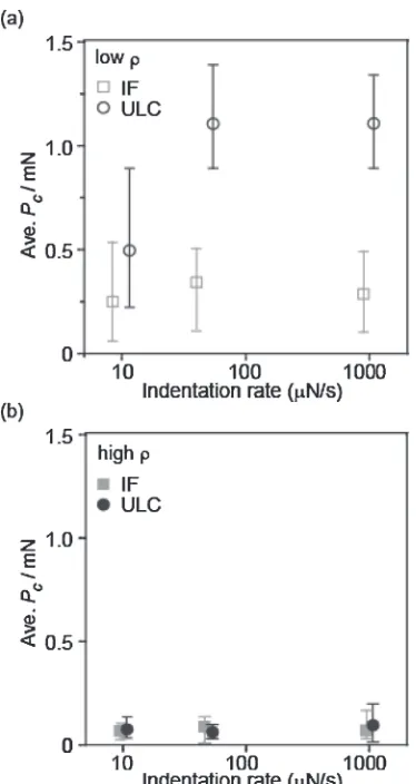
would show an indentation rate dependence mentioned in the previous paper.12)Figures 6(a) and 6(b) show the indentation
rate dependence with low and high dislocation density Fig. 4 The relationship betweenPcand"hfor IF and ULC with (a),(b) low dislocation density and (c),(d) high dislocation density.
[image:4.595.153.444.71.377.2] [image:4.595.55.284.417.634.2]materials, respectively. In low dislocation density materials, the Pc in ULC shows a clear indentation rate dependence,
while in high dislocation density materials, neither IF nor ULC shows any indentation rate dependence. These results indicate that there is no effect of interstitial carbon on the pop-in event for the high dislocation density materials.
The effect of carbon on high dislocation density materials is considered as follows. As mentioned above, we proposed that the interstitial carbon provides a higher friction stress against an edge dislocation movement while the nucleated shear loop develops into a FrankRead source. On the other hand, the high dislocation density materials already contain many dislocation sources which have a longer FrankRead length with a lower critical load for multiplication once an indent is made. Therefore the dislocation nucleation is unnecessary and the process of shear loop growth, which is affected by carbon, does not occur.
Shim et al. reported that a difference in the indenter size produced different highly stressed zones and explained the relationship between the size of a highly stressed zone and the dislocation density through a schematic image.18)We also drew a schematic image of our results in Fig. 7. Figures 7(a) and 7(b) show the image of IF and ULC with low dislocation density, and Figs. 7(c) and 7(d) show the image of IF and ULC with high dislocation density. The highly stressed zone of the ULC with low dislocation density in Fig. 7(b) consists
of carbon with few pre-existing dislocations. On the other hand, the highly stressed zone of the ULC with high dislocation density in Fig. 7(d) contains not only carbon but also many dislocations. Next we discuss the two reasons why the carbon does not have any effect on the ULC with high dislocation density when the dislocation multiplication occurs.
Thefirst reason is that the dislocation without any carbon pinning could be the dominating mechanism. Brittonet al.19)
discussed the relationship between the amount of carbon and the dislocation density for the pop-in using the Fe 0.01 mass%C polycrystal (bcc) based on the model by Cottrell and Bilby.20) The model describes the effect of
carbon contents ½ (mass%) on the stressstrain curve of steels with different dislocation densitiesμ(m¹2). The yield drop is shown to appears on the stressstrain curve when
½=μ1018 ðmass%m2Þ; ð7Þ in contrast, the yield drop does not appear when
½=μ1019 ðmass%m2Þ: ð8Þ Thus, they concluded that pop-ins do not occur when the sample contains many dislocations since there is not enough carbon contents to pin all the dislocations, which corresponds to the case of the ULC with high dislocation density in our study. The carbon content in the ULC is 0.0038 mass%with a low dislocation density of 1011m¹2 and a high dislocation
density of 1014m¹2.½/μis estimated to be 10¹14(mass%m2)
for low dislocation density, which satisfies eq. (7) resulting in a pop-in and 10¹17 (mass%m2) for high dislocation density which is two orders higher with the critical value in eq. (8). However, the carbon content could be overestimated in the grain interior because we ignored the carbon segregation to the grain boundaries. Additionally, the dislocation density could be underestimated since we measured it within the dislocation cells and did not count the dislocations on the cell walls. Therefore, the actual value of ½/μ could be much lower than the estimated value and correspond to the case of eq. (8). Consequently, we could assume the possibility that some of the pre-existing dislocations might not be pinned by Fig. 6 Indentation rate dependence for IF and ULC with (a) low
dislocation density and (b) high dislocation density.
[image:5.595.77.264.67.419.2] [image:5.595.303.545.70.252.2]carbon and are able to move in the same way as dislocations in the IF, since many dislocation sources exist underneath the indenter. The schematic image of this case is shown in Fig. 7(d1).
The other reason is that the critical stress for dislocation source activation is more dominant than the occurrence of the unpinning from carbon. We estimated the practical balance between the carbon contents and the dislocation density for the ULC with high dislocation density. In this estimation, all the carbon exists in the grain interior with no segregation or precipitation. The number of carbon atoms per unit volume
Nc
vin the ULC estimated from the composition of carbon is
as follows. The carbon contents in the ULC is 0.0177 at%, thus the mean spacing of carbon is estimated to be around 4 nm, andNc
vis calculated to be 1.6©1025m¹3. On the other
hand, the number of carbon atoms existing on a dislocation
Nd
vis estimated from the dislocation density. We assume the
spacing of the carbon to be 0.29 nm, which is the nearest neighbor of the octahedral site. Nd
vis obtained by dividing
the dislocation density (1014m¹2) by the spacing of carbon atoms (0.29 nm) and calculated to be 3.4©1023m¹3. From these estimations,Ncvis much larger thanNdv, indicating that
the carbon content seems to be high enough to pin all the dislocations as schematically shown in Fig. 7(d2). Thus,
another possibility should be considered. When all the dislocations or dislocation sources beneath the indenter are pinned by carbon, the critical stress ¸p for the dislocation
multiplication of pre-existing dislocation based on a line tension model for a tensile deformation induced FrankRead type source is expressed as:
¸p¼Gbl
p ; ð9Þ
where lp is the tensile deformation induced FrankRead
length. ¸p is dominant if the stress for unpinning from the
carbon is lower than¸p. It is not easy to estimate the stress for
unpinning from the carbon; however, the yield stress given by the tensile test is around 300 MPa,12)and the dislocation can move at this stress level for the initiation of the deformation. On the other hand, the¸maxcalculated fromPc
in eq. (4) is around 8 GPa as shown in Table 2. Since there is a stress distribution underneath the indenter and the position of the activated dislocation source could be far from that of the¸max, the actual ¸pmight be lower than 8 GPa. However,
the ¸pcould still be much higher than the yield stress level.
Thus, the critical stress ¸p for the activation of the tensile
deformation induced pre-existing dislocation source is domi-nant for the pop-in and the unpinning from the carbon has no effect on the ULC with high dislocation density. In this case, thePcis associated with the¸pin eq. (9); hence¸cand lcin
eq. (5) have no relation to Pc. Therefore, the effect of
in-solution carbon on the dislocation mobility leading to the dislocation source formation does not have to be considered.
4. Summary
The effect of pre-existing dislocation and interstitial carbon on the pop-in behavior was investigated using the IF and
ULC steels. The steels with high dislocation density showed a smaller Pc than those with low dislocation density since
they contained many pre-existing dislocations and dislocation sources that can multiply at a lower load. There was no difference in the averagePcvalue between the IF and ULC
with high dislocation density. The ULC also did not show any indentation rate dependence, suggesting that the interstitial carbon does not have any effect on the pop-in behavior. One presumable reason for this behavior is that some of the pre-existing dislocation sources might not be pinned by carbon. Another factor might be that the stress for unpinning is lower than the critical stress against the line tension for activating the tensile deformation induced dislocation source. Therefore the stress to initiate the plastic deformation does not depend on the carbon content when the materials contain sufficient dislocations or dislocation sources.
Acknowledgements
The steel sheets in this study were supplied by Steel Research Laboratories, Nippon Steel Corporation. This study was supported by JST, CREST. K.S. acknowledges the National Institute for Materials Science (NIMS) for the provision of a NIMS Graduate Research Assistantship.
REFERENCES
1) E. Carrasco, M. A. Gonzalez, O. Rodriguez De La Fuente and J. M. Rojo:Surf. Sci.572(2004) 467475.
2) J. Li, K. J. Van Vliet, T. Zhu, S. Yip and S. Suresh:Nature418(2002) 307310.
3) J. K. Mason, A. C. Lund and C. A. Schuh: Phys. Rev. B73(2006) 114.
4) A. M. Minor, S. A. Syed Asif, Z. Shan, E. A. Stach, E. Cryankowski, T. J. Wyrobek and O. L. Warren:Nature Mater.5(2006) 697702. 5) O. Rodrguez De La Fuente, J. A. Zimmerman, M. A. Gonzlez, J. De La
Figuera, J. C. Hamilton, W. W. Pai and J. M. Rojo:Phys. Rev. Lett.88
(2002) 036101036104.
6) C. A. Schuh:Mater. Today9(2006) 3240.
7) C. A. Schuh, J. K. Mason and A. C. Lund:Nature Mater.4(2005) 617 621.
8) T. Ohmura and K. Tsuzaki:J. Mater. Sci.42(2007) 17281732. 9) W. Wang, C. B. Jiang and K. Lu:Acta Mater.51(2003) 61696180. 10) A. A. Zbib and D. F. Bahr:Metall. Mater. Trans. A Phys. Metall. Mater.
Sci.38A(2007) 22492255.
11) A. Barnoush, M. T. Welsch and H. Vehoff:Scr. Mater.63(2010) 465 468.
12) K. Sekido, T. Ohmura, L. Zhang, T. Hara and K. Tsuzaki:Mater. Sci. Eng. A530(2011) 396401.
13) W. C. Oliver and G. M. Pharr:J. Mater. Res.7(1992) 15641580. 14) K. L. Jonson: Contact Mechanics, (Cambridge University Press,
Cambridge, UK, 1985) pp. 84106.
15) T. Ohmura, K. Tsuzaki and F. Yin:Mater. Trans.46(2005) 20262029. 16) H. S. Leipner, D. Lorenz, A. Zeckzer, H. Lei and P. Grau:Physica B
308310(2001) 446449.
17) E. Clouet, S. Garruchet, H. Nguyen, M. Perez and C. S. Becquart:Acta Mater.56(2008) 34503460.
18) S. Shim, H. Bei, E. P. George and G. M. Pharr:Scr. Mater.59(2008) 10951098.
19) T. B. Britton, D. Randman and A. J. Wilkinson: J. Mater. Res.24
(2009) 607615.