Numerical Simulation and Preparation of Cladding Billet
by Direct Chill Semi-Continuous Casting
Han Xing, Zhang Haitao
+, Shao Bo, Zuo Kesheng, He Lizi, Qin Ke and Cui Jianzhong
Key Laboratory of Electromagnetic Processing of Materials, Ministry of Education, Northeastern University, Shenyang 110819, China
This study presents an innovative direct chill semi-continuous casting process to prepare AA4045/AA3003 cladding billet using numerical simulation and experiments. The influence of casting speed on temperaturefield in cladding billet has been investigated by the commercial software FLUENT and validated by experiments. The cladding billet was examined by methods of metallographic examination,field emission scanning electron microscopy (FESM) and universal testing machine. The results show that the experiments are in good agreement with the simulation results. Cladding billets can be obtained at the casting speeds ranging from 110 mm/min to 150 mm/min. Excellent metallurgical bonding of the two alloys could be achieved at the casting speed of 130 mm/min and 150 mm/min. With the increase of casting speed, increasing contact temperature promotes the interdiffusion of alloy elements. The tensile strength and shear strength of interface reaches 106 MPa and 77 MPa respectively. Moreover, fracture position moves to AA3003 side from the interface in tensile test, while fracture mode changes to the ductile from the brittle as casting speed increases. [doi:10.2320/matertrans.M2015229]
(Received June 5, 2015; Accepted August 27, 2015; Published October 25, 2015)
Keywords: cladding billet, casting speed, contact temperature, diffusion, interfacial strength
1. Introduction
As the existing and potential industrial applications, multi-layer materials laminate or cladding tubular products is
playing a more and more significant role in modern industries
because of their advantages, such as excellently physical, chemical and mechanical performance that conventional
monolithic materials do not have.14) Tubular products or
sheets could be extensively used to make corrosion resistant aluminum products, radiator, heat exchangers, condenser
pipes, and so on.5)In the past decades, a series of processes
used for preparation of cladding materials had been
developed, involving rolling bonding,6,7) explosive
weld-ing,8,9) diffusion bonding,10) extrusion cladding,11,12) spray
deposition technique13)et al.However, the adherence issue of
the mating surface between the clad and core layers could not be resolved properly, thus limiting the strength of the laminated billets. To overcome such a challenge, Novelis
has recently developed the FushionTM Technology process
that allows simultaneously direct-chill casting single or double alloy layers into a single aluminum rolling billet for manufacturing various types of multiple alloy or clad sheets
products.14) E.I. Marukovich et al.15)studied the possibility
experimentally and numerically for producing bimetallic components by mean of horizontal continuous-casting in condition of direct connection of metals in a liquid state.
AMIR R. Baserinia et al.16) developed a numerical
steady-state thermofluids model for the FusionTM technology casting
process to simulate the casting of rectangular bimetallic billets
and conducted to cast AA3003/AA4045 clad ingots via
FusionTM Technology. Fuet al.17)prepared 1Mn and
Al-10Si alloys circular clad ingot by direct chill semi-continuous casting. However, in some particular conditions, bimetal materials are required to be tubular or wirelike and satisfy the
strict standard of the clad ratio.18)Most processes mentioned
above focused on how to achieve composite ingot. Neither the
investigations of cladding billet with a low clad ratio, nor the effect of process parameters on cladding billet, has been reported because of the requirement of more complex crystallizer system and advanced casting technology.
In this paper, the casting process of cladding billets was investigated by numerical simulation and experiments. The
influence of casting speed on the formability and bonding of
the two alloys was discussed in detail.
2. Methodology
2.1 Mathematical model of the cladding casting process
To investigate the influence of casting parameters on the
cladding billet, a mathematical model is used to describe the cladding casting process.
In this study, a single domain volume-average model is applied to the clad and core materials. Single region models are built on governing equations that apply to all regions of
solidification system. The model equations can be integrated
across the entire domain without the need to explicitly
subdivide the domain into solid, liquid and mushy regions.19)
Instead, these regions are implicitly defined within the system
by distributions of energy determined from the solutions
model equations. The flow field of melts is described by
conservation equation of mass and conservation equation of
momentum, and temperature fields are described by the
conservation equation of energy. In this model, the fluid
flow, heat transfer and solidification are coupled so that the
interaction of the multi-physicsfield during the process could
be described accurately. The interface of the two alloys is treated as stationary wall relatively, and the heat transfer of them is coupled.
In order to simplify the question, some assumptions are given as follow:
(1) The calculation about the solutefield is not included in
the research;
(2) The interaction between two kinds of melts is negligible;
+Corresponding author, E-mail: haitao_zhang@epm.neu.edu.cn
(3) The melts in the mold are taken as homogeneous medium;
(4) Aluminum alloy is deemed to be incompressiblefluid,
namely its density is a constant. But the thermal buoyancy must be included in this model; therefore the Boussinesq approximation is used to calculate the thermal buoyancy and is expressed as:
Fthermal¼µl¢ðTT0Þ ð1Þ
Whereµ1and¢are the density and the volume expansion
coefficient of the molten aluminum, respectively, T0 is the
reference temperature and is frequently given as the temper-ature of the solid fraction of dendrite contact.
In AA4045/AA3003 cladding billet of cladding casting
process, the solidified part moves along the axial with casting
speed.
According to above assumptions, the governing equations
[image:2.595.155.539.80.406.2]used in the mathematic model are modified as shown in
Table 1. In these equations,®effandSmare effective viscosity
and momentum source, respectively. The effective viscosity
®effis given by®eff=®l+®t, where ®lis laminar viscosity
in the liquid and ®t is turbulent viscosity. The momentum
sourceSmincludes thermal buoyancy and Darcy source term.
In the eq. (4), Sth is thermal source, i.e., latent heat of
solidification. K,xare permeability and very small positive
number to avoid diverging of conversation equations.
Permeability K is given as a function of solid fraction fs,
i.e., K¼K0ð1fsÞ3=fs. Gk represents the generation of
turbulence kinetic energy due to the mean velocity gradients,
calculated as follows: Gk¼ µ®0®0jð¿®j=¿xiÞ. C1 and C2
are constants.·kand·¾ are the turbulent Prandtl number for
kand¾, respectively.
In addition, the lower Reynold numbers model is applied because it has relatively low mesh requirements and is widely
used and verified in various numerical engineering
applica-tions. A one-half symmetry model is used to reduce the calculation amount. The mesh model and boundaries are
shown in Fig. 1. From the former work,20) the boundary
conditions are set in detail. The thermophysical properties and other material properties of the alloys used during the calculation procedure are listed in Table 2.
2.2 Materials and experiments
As commonly used commercial alloys, AA4045 has remarkable weldability, while AA3003 has excellent corro-sion resistance. Their components are list in Table 3. The condenser pipe prepared by the two aluminum alloys could combine their advantages and be available to the automotive
heat exchangers for automobile lightening.21)
The apparatus of semi-continuous casting for fabricating cladding billets were designed and schematically shown in Fig. 2. It mainly contains inner-crystallizer, outer-crystallizer, their respective pouring system and cooling system. During the casting process, AA3003 was poured into the
inner-Table 1 Governing equations used in the model.
Governing equations’name Modified governing equation
Conservation equation of mass r•U¼0
Conservation equation of momentum r•ðµUUÞ ¼ r•ð®effrUÞ rPþSm
Conservation equation of energy r•ðµUTÞ ¼ r• k
CprT
þSth
Conservation equation of turbulence kinetic energy r•ðµUkÞ ¼ r• ®1þ®1 ·k
rk
þGkµ¾K®þ1»k
Conservation equation of dissipation rate of
turbulence kinetic energy r•ðµU¾Þ ¼ r• ®1þ
®t
·¾
r¾
þC1k¾GkC2µ¾
2
k K®þ1»¾
(a) (b)
1 2
3
4
5
6
7
8
9
[image:2.595.48.552.82.408.2]Fig. 1 The computational mesh model (a) and boundary conditions (b): 1 free surface; 2 inlet-AA3003; 3 inner mold; 4 inlet-AA4045; 5 outer mold; 6 second cooling; 7 interface; 8 outlet; 9 symmetry axis.
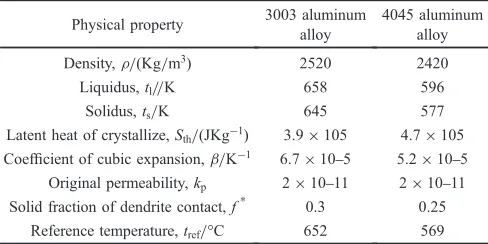
Table 2 Physical properties and constants used in the numerical simulation.
Physical property 3003 aluminum
alloy
4045 aluminum alloy
Density,µ/(Kg/m3) 2520 2420
Liquidus,tl//K 658 596
Solidus,ts/K 645 577
Latent heat of crystallize,Sth/(JKg¹1) 3.9©105 4.7©105
Coefficient of cubic expansion,¢/K¹1 6.7©105 5.2©105
Original permeability,kp 2©1011 2©1011
Solid fraction of dendrite contact,f* 0.3 0.25
[image:2.595.305.549.475.597.2]Reference temperature,tref/°C 652 569
Table 3 Alloy compositions.
Elements Si Fe Cu Mn Mg Zn Ti Al
mass%
(AA3003) 0.6 0.7 0.05³0.20 1.0³1.5 ® 0.10 ® Balanced
mass%
[image:2.595.304.549.631.694.2]crystallizer firstly. Under the cooling of the inner-mold, a supporting layer would form at the inner-graphite in several seconds. When the strength of the supporting layer was
sufficient to prop up the internal liquid metal and the surface
of the supporting layer remained at relatively high temper-ature, AA4045 was poured into the outer-crystallizer rapidly
and flowed into the outer-crystallizer, and the starting head
was drown at the same time. Then, the casting of cladding billets began when AA4045 melt contacted with the supporting layer of AA3003. Finally, the cladding billet in
size of¯140 mm/¯110 mm was prepared successfully.
In authors’ former work, a comprehensive mathematical
model had been developed to describe the variation and the
interaction of the multiple physicsfields during the cladding
casting process. The model has been verified by
experi-ments.20)The present study aimed to investigate the influence
of casting speed on temperature field, the formability and
bonding of the two alloys. Basing on the simulation results, the casting speed takes several different values, remaining other technical parameters constants as list in Table 4.
The as-cast samples were polished and etched using a
solution of 10% NaOH (in mass) to observe the
macro-structure, another solution of 5%HF (in volume) to examine
the microstructure by metalloscope (Leica DMR), respec-tively. The distribution of the Si and Mn elements across the interface at different casting speed was analyzed by scanning electron microscope (Zeiss Ultra Plus 60). In order to evaluate the interfacial strength of different cladding billets,
the tensile test and the shear test were performed by MTS-810 universal testing machine.
Samples to investigate mechanical properties were cut across the interface as the similar position, tensile specimen (a) and shear specimen (b) in Fig. 3.
3. Results and Discussion
3.1 Simulation results of cladding casting
Based on the above simulation model and basic
assump-tions, the temperature profiles during the stable period of
direct chill semi-continuous casting were obtained with
casting speed, 90 mm/min, 110 mm/min, 130 mm/min, 150
mm/min and 170 mm/min, respectively, as shown in Fig. 4.
It can be known that AA3003 melt close to the inner-mold was cooled, formed gradually a supporting layer and reheated by AA4045 melt poured into the outer-mold. As casting, the cladding billet was cooled to room temperature. Moreover, with the increase of casting speed, the temperature (called
1 6
7 8 9 2 3 4 5 10 11
12
[image:3.595.56.284.71.220.2]Fig. 2 Schematic diagrams of cladding casting equipment: crystal-lizer, 1 clad tundish, 2 launder, 3 graphite, 4 cooling water, 5 outer-mold; inner-crystallizer, 6 core tundish, 7 inner-graphite, 8 inner-mold, 9 cooling water; 10 bonding interface; 11 cladding billet; 12 starting head.
Table 4 Casting process parameters during the cladding casting.
alloys Casting temperature
/°C
Casting speed
/mm·min¹1
Cooling waterflow rate
/L·min¹1
AA3003 720 90170 30
AA4045 730 90170 60
R55mm
2mm 30°
(b)
R2mm 1.5mm
3mm 10mm (a)
a b
interface
AA4045
AA3003
Fig. 3 Schematic illustration of sampling location of tensile (a) and shear (b) specimens.
(a) (b) (c) (d) (e)
[image:3.595.305.548.73.187.2] [image:3.595.118.484.286.398.2] [image:3.595.305.548.467.517.2]contact temperature), where AA4045 melt just contacted with
the supporting layer of AA3003, has a significant increase, as
well as the depth of the sump.
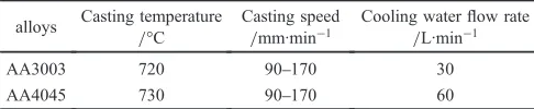
In order to investigate the variation of temperature field
and obtain a proper casting speed range, the temperature data of composite interface and center zone is extracted and drawn into cooling curves, as shown in Fig. 5 and Fig. 6. With the increasing of casting speed, the staying time of melts in the contact, primary and secondary cooling zones decreases, so that the supporting layer is cladded by AA4045 with a higher temperature. Therefore, the contract temperature increases from 557°C to 652°C, as shown in Fig. 5(b). Similarly, as a result of cooling time shortening, the sump depth elongates from 42 mm to 188 mm, as shown in Fig. 6(b).
In theory, the lager casting speed, the higher contact temperature, the faster alloy elements diffuse and the higher productivity. However, in the cladding casting process, when
the casting speed reaches 170 mm/min, the contact
temper-ature would reach the AA3003 liquidus (652°C), and the
solidified supporting layer will be remelt badly by AA4045
melt, even mix with it. In addition, a larger sump depth could
increase the stress, which maybe produces cracks.22) While
the casting speed is down to 90 mm/min, the contact
temperature is just 557°C, lower than the AA4045 solidus, resulting in that AA4045 starts to solidify before contact with the supporting layer.
Based on the simulation results, the casting speed of
AA4045/AA3003 cladding billet with no breaking
support-ing layer or discontinusupport-ing castsupport-ing process is predicted at a
range from 110 mm/min to 150 mm/min.
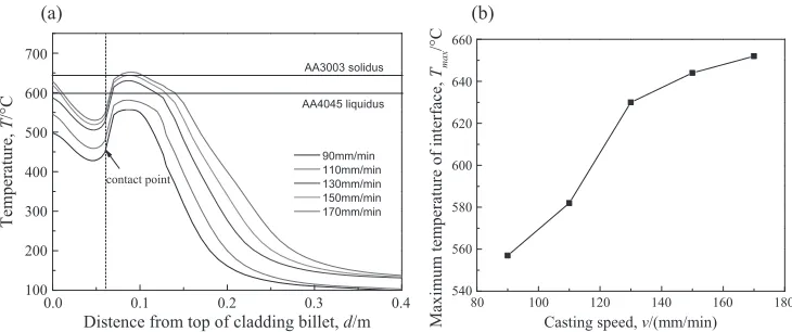
3.2 Experimental results
As shown in Fig. 7, cladding billets were cast by direct chill semi-continuous process at different casting speed,
90 mm/min, 110 mm/min, 130 mm/min, 150 mm/min, and
170 mm/min, respectively. The result shows that when
casting speed is equal 90 mm/min, the AA4045 melt was
cooled excessively and could hardlyflow freely. As a result,
the mold filling was insufficient, AA4045 had already
solidified before flowing into outer-graphite and the two
alloys were separated from each other, as shown in Fig. 7(a).
When casting speed is equal 170 mm/min, the contact
temperature is higher than the AA3003 liquidus. The overheated melt in the center of AA3003 would break through the thinner supporting layer, the solidifying AA4045
flowed out, and the two alloys were mixed, as marked in
Fig. 7(e). In the end, cladding casting has to be stopped. Therefore, the cladding billets with an excellent surface quality and well interface were prepared at casting speed of
110 mm/min, 130 mm/min and 150 mm/min, as shown in
Fig. 7(b), (c), (d).
During the casting process, the contact temperature should be in range of the AA4045 solidus to the AA3003 liquidus.
This ensures that AA4045 could flow freely and would not
remelt the supporting layer. With the matching, casting speed
should be range of 110 mm/min to 150 mm/min for
0.0 0.1 0.2 0.3 0.4 100
200 300 400 500 600 700
contact point
AA4045 liquidus AA3003 solidus
Temperature,
T
/
°
C
Distence from top of cladding billet, d/m 90mm/min 110mm/min 130mm/min 150mm/min 170mm/min
80 100 120 140 160 180
540 560 580 600 620 640 660
Maxim
um tem
perature of interface,
Tma
x
/
°
C
Casting speed, v/(mm/min)
(a) (b)
Fig. 5 Cooling curves of composite interface.
0.0 0.1 0.2 0.3 0.4 0.5
200 400 600 800
90mm/min 110mm/min 130mm/min 150mm/min 170mm/min
Temperature,
T
/
°
C
Distence from top of cladding billet, d/m
80 100 120 140 160 180
50 100 150 200
The sump depth,
d s
/mm
Casting speed, v/(mm/min)
(a) (b)
[image:4.595.116.481.70.223.2] [image:4.595.124.472.261.410.2]AA4045/AA3003 in size of ¯140 mm/¯110 mm cladding casting. The experiment results have a good agreement with the simulation. The simulation result could play a guiding
significance role in the the experiments.
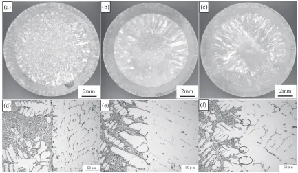
3.3 Microstructure and mechanical properties of clad-ding billets
The cladding billets were prepared successfully at different
casting speed, 110 mm/min, 130 mm/min and 150 mm/min
respectively, using the process parameters obtained from numerical simulation. The macrostructures and microstruc-tures at different casting speed are displayed in Fig. 8. The two alloy layers are revealed by two different contrasts. The interfaces separate the two layers clearly, as shown in Fig. 8(a), (b), (c). After AA3003 was poured into the
inner-crystallizer, some equiaxed grains formed on the substrates of heterogeneous nucleation at the core-layer interior. Then, AA3003 continued to solidify along the heat transfer direction, forming the coarse columnar zone. At the center of core-layer, the isotropic heat transfer resulted in forming
coarser equiaxed grains. AA4045 flowed into the
outer-crystallizer and was cooled by outer-outer-crystallizer more
intensely and AA3003 solidification shell of less intensely.
Therefore, the clad-layer external was composed of fine
equiaxed grains, whereas the internal was consisted of coarse columnar crystals.
Casting speed affected the macrostructure obviously. As casting speed increase, on the one hand, the cooling time for AA3003 melt will be shortened, resulting in that the supporting layer contacts with AA4045 at a higher
temper-(a) (b) (c) (d) (e)
Fig. 7 Photographs of cladding billets cast at the different casting speeds: (a)v=90 mm/min; (b) v=110 mm/min; (c) v=130 mm/min; (d)v=150 mm/min; (e)v=170 mm/min.
(a)
2mm (b)
2mm (c)
2mm
(d) (e) (f)
[image:5.595.113.484.69.258.2] [image:5.595.81.514.302.554.2]ature. On the other hand, the temperature gradient in solidifying forefront decreases, lessening the degree of supercooling. A lower degree of supercooling will restrains
the nucleation but promotes grains growing.23)For AA3003,
the area of columnar structures increased and the grain size enlarged, while the equiaxed zone decreased and the grain size reduced with the increase of casting speed. However, there was little disparity in AA4045.
The micro-interface is shown in Fig. 8(d), (e), (f ). It can be seen that acicular eutectic silicon crystals (black part) are
distributed at the boundaries of the coarse¡-Al grains (white
part) in AA4045; whereas some phases containing
manga-nese (black parts) are embedded in the ¡-Al matrix (white
part) in AA3003. When the casting speed is 110 mm/min, the
contact temperature was only 582°C (just above AA4045 solidus, 577°C), reaching eutectic temperature of Al-Si and precipitating eutectic directly. Therefore, AA4045 started to solidify before contacted the supporting layer of AA3003. There was no full diffusion during the process of bonding
and solidification of the two alloys. With the increasing of
casting speed, reaching 130 mm/min, the contact temperature
reached over 630°C (higher than AA4045 solidus, 577°C, but
lower than AA3003 liquidus, 645°C). The primary ¡-Al
grains of AA4045 precipitated firstly and grew attaching to
the supporting layer. The eutectic silicon precipitated with the reaching eutectic temperature at the interface. However, when
casting 150 mm/min, the contact temperature was 644°C
(closed to AA3003 liquidus, 645°C), resulting in some excessive re-melting of supporting layer, as shown in Fig. 8(f ).
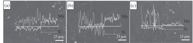
Figure 9 presents the energy dispersive X-ray spectro-scope (EDX) linear scan analysis of Si and Mn across the composite interface. Clear concentration differences are observed for the two elements. The content of the element Si clearly decreases from AA4045 to AA3003, while the content of the element Mn increases across the bonding interface. With casting speed increase, the Mn element had lager degree of diffusion so that some phases containing manganese formed when the casting speed reached 150
mm/min (as shown in Fig. 8(c)), while the diffusion of Si
element had little variation.
According the Fick’s laws of diffusion, if the diffusion
process of every element is independent, the diffusion equation can be shown as
@C @t ¼D
@2C
@x2 ð2Þ
The diffusion coefficientDcan be analyzed by following
equation
D¼D0exp RTQ
ð3Þ
whereD0is the diffusion constant,Qis activation energy for
diffusion,Ris the universal gas constant andTis the absolute
temperature.
From the above equations, the temperature played a key
role in affecting the diffusion coefficient. As the increase of
casting speed, on the one hand, the contact temperature rose up. The alloy elements had lager vibrational energy to get
over the barrier by energeticfluctuation and a relatively large
diffusion coefficient. On the other hand, the contact time in
solid-liquid state decreased, resulting in the diffusion time shortened. However, the former has an exponential effect on the diffusion of alloy elements, but the later has a linear. In addition, the Mn element diffused from solid AA3003 to liquid AA4045, while the Si element diffused reversely. There is a higher diffusion rate from liquid to solid than that
conversely.24) Therefore, the increasing of casting speed,
resulting in the contact temperature rising up, further accelerated the diffusion of Mn atoms than Si atoms, as shown in Fig. 9(a), (b), (c).
3.4 Interfacial mechanical properties
Tensile test is an efficient approach to estimate the
interface bonding. Figure 10 shows the fractured tensile samples for different casting speeds. Increasing casting speed led to the site of fracture interface into substrate AA3003. The tensile strength of the composite interface and the substrate AA3003 at different casting speeds are shown in Fig. 11. The casting speed has a greater effect on interface bonding. For sample (a), the fracture occurred at the composite interface with average tensile strength, 64.2 MPa,
25 μm
(a)
Mn
Si
25 μm
(b)
Mn
Si
25 μm
(c)
Mn Si
Fig. 9 The EDX analysis results of the cladding billets in different casting speeds: (a) v=110 mm/min; (b) v=130 mm/min; (c)v=150 mm/min.
10mm AA4045
interface
AA3003 (a)
(b)
[image:6.595.112.479.70.152.2](c)
[image:6.595.344.514.204.335.2]lower than substrate AA3003, 105 MPa. At 110 mm/min, lower contact temperature slowed down the diffusion at the composite interface, corresponding to the EDX analysis result in Fig. 8(a). For sample (b) and sample (c), their tensile strength is near that of substrate AA3003 and the fracture occurred at the AA3003 side, while the interface remains well. Higher contact temperature, which was brought by casting speed increasing, made the alloy elements diffuse
adequately. Therefore, when casting speed reach 130 mm/
min or higher within a limited range, the two alloys bonded metallurgical.
Shearing test reflects quantitatively interface bonding
strength, rather than tensile test confirming qualitatively that
bonding strength is higher than the softer substrate. Mean-while, shearing strength could provide reliable parameters for subsequent composite pipe extrusion. With reference to the
standards by Jing,25,26) shear strength is tested and shown
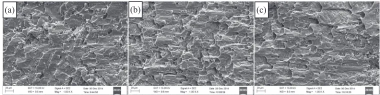
in Fig. 12. The FESEM micrographs of shear fracture of AA3003 side reveal the shear results, as shown in Fig. 13.
At 110 mm/min, the shear strength of composite interface is
lower than that of substrate AA3003, and the shear fracture with few dimples reveals that brittle failure occurred at the composite interface (Fig. 13(a)), indicating that the two alloys contacted through little diffusion. Increasing casting speed led to an increase in shear strength due to greater interdiffusion of the alloy elements (Si and Mn) in both alloys. In contrast, fracture surfaces of composite interface at
casting speeds (130 mm/min and 150 mm/min) show ductile
failure such as a number of dimples (Fig. 13(b), (c)). The shear strength of composite interface increased obviously and exceeded substrate AA3003, due to more adequate diffusion with higher casting speed.
Consequently, there is a well agreement among the microstructures, the EDX analysis results and the mechanical properties of composite interface with different casting speed.
4. Conclusions
A mathematic model for the coupled of fluid flow, heat
transfer and solidification to describe the process of cladding
casting was present. The effect of casting speed on
temper-ature field and solidification process was vestigated. The
model has been verified by the fabrication of AA4045/
AA3003 cladding billet. It was found that there was a good agreement between the simulation results and experiment and the following conclusions were drawn:
(1) The mathematic model is accurate and credible to describe the process of cladding casting with various technological parameters.
(2) With the increase of casting speed, the contact temper-ature rises up and the sump depth would be elongated
observably. Too low (90 mm/min) and too high
(170 mm/min) casting speed would lead to the failure
of the cladding casting, because of early solidification
of AA4045 and melting through the supporting layer, respectively.
(3) The increasing of casting speed, resulting in the contact temperature rising up, further accelerated the diffusion of Mn atoms than Si atoms. It is practical to prepare
AA4045/AA3003 cladding billet in size of¯140 mm/
¯110 mm by direct chill semi-continuous casting
process with casting speed ranging from 130 mm/min
to 150 mm/min.
(4) Increasing of casting speed intensifies the interdiffusion
110mm/min 130mm/min 150mm/min
0 30 60 90 120 150
Tensile strength of cladding billet Tensile strength of subtrate AA3003
Tensile strength,
Rm
[image:7.595.76.264.68.206.2]/MPa
Fig. 11 The tensile strength of the cladding billets and substrate AA3003 at different casting speeds.
110mm/min 130mm/min 150mm/min
0 30 60 90 120
Shear strength,
σc
/MPa
[image:7.595.344.512.72.204.2]Shear strength of cladding ingot Shear strength of subtrate AA3003
Fig. 12 The shear strength at different casting speeds.
(c) (b)
(a)
[image:7.595.107.487.252.347.2]of alloy elements. When casting speed reaches or
greater than 130 mm/min, the diffusion of alloy
elements is enhanced markedly. Correspondingly, the interfacial strength exceeds substrate AA3003, 106 MPa in tensile test and 77 MPa of shear strength, respec-tively. It means that the two alloys achieved a well metallurgical bonding.
Acknowledgments
The authors gratefully acknowledge the supports of the National Basic Research Program of China (Grant number 2012CB723307-03), the National Science Foundation for the Youth (Grant number 51204046) and the doctoral foundation of China Ministry of Education (Grant number 20130042130001).
REFERENCES
1) W. S. Miller, L. Zhuang, J. Bottema, A. J. Wittebrood, P. D. Smet, A. Haszler and A. Vieregge:Mater. Sci. Eng. A280(2000) 3749. 2) K. J. M. Papis, B. Hallstedt, J. F. Loffler and P. J. Uggowiter: Acta
Mater.56(2008) 30363043.
3) I. K. Kim and S. I. Hong:Mater. Des.49(2013) 935944.
4) T. Liu, Q. D. Wang, Y. D. Sui, Q. G. Wang and W. J. Ding:Mater. Des. 68(2015) 817.
5) Y. Liu and Z. T. Wang: Light Alloy Fabricat. Technol.39(2011) 116. 6) M. Talebian and M. Alizadeh:Mater. Sci. Eng. A590(2014) 186193. 7) M. Z. Quadir, M. Ferry, O. Al-Buhamad and P. R. Munroe: Acta.
Mater.57(2009) 2940.
8) S. Niknejad, L. Liu, M. Y. Lee, S. Esmaeili and N. Y. Zhou:Mater. Sci.
Eng. A618(2014) 323334.
9) M. Asemabadi, M. Sedighi and M. Honarpisheh:Mater. Sci. Eng. A 558(2012) 144149.
10) J. Zhang, G. Q. Luo, Y. Y. Wang, Q. Shen and L. M. Zhang:Mater. Lett.83(2012) 189191.
11) C. G. Kang, Y. J. Jung and H. C. Kwon:J. Mater. Process. Technol.124 (2002) 4956.
12) K. Y. Rhee, W. Y. Han, H. J. Park and S. S. Kim:Mater. Sci. Eng. A 384(2004) 7076.
13) Q. Tang, H. F. Ning, D. F. Fu, W. J. Xia, Z. H. Chen and H. L. Ning: Powder Metall. Technol.22(2004) 1215.
14) J. C. Bendyk: Light Metal Age8(2006) 4850.
15) E. I. Marukovich, A. M. Branovitsky, Y. S. Na, J. H. Lee and K. Y. Choi:Mater. Des.27(2006) 10161026.
16) A. R. Baserinia, H. Ng, D. C. Weckman, M. A. Wells, S. Barker and M. Gallerneault:Metall. Mater. Trans. B43(2012) 887901.
17) Y. Fu, J. C. Jie, L. Wu, J. Park, J. B. Sun, J. Kim and T. J. Li:Mater. Sci. Eng. A561(2013) 239244.
18) W. P. Gan and J. H. Wei: Nonferrous Metals8(1998) 206209. 19) H. T. Zhang, H. Nagaumi, Y. B. Zuo and J. Z. Cui:Mater. Sci. Eng. A
448(2007) 189203.
20) X. Han, B. Shao, H. T. Zhang and J. Z. Cui: J. Northeastern Univ. (Natural Science)35(2014) 969973.
21) D. M. Turriff, S. F. Corbin and M. Kozdras:Acta Mater.58(2010) 13321341.
22) Y. B. Zuo, J. Z. Cui, Z. H. Zhao, H. T. Zhang and K. Qin:Mater. Sci. Eng. A406(2005) 286292.
23) A. E. Ares and C. E. Schvezov: Metall. Mater. Trans. A38(2007) 14851499.
24) W. Yao, A. P. Wu, G. S. Zou and J. L. Ren: Rare Metal Mater. Eng.36 (2007) 700704.
25) Y. A. Jing, Y. Qin, X. M. Zang, Q. Y. Shang and H. Song:J. Alloy. Compd.617(2014) 688698.