warwick.ac.uk/lib-publications
Original citation:
Liu, Teng, Gao, Weiguo, Zhang, Dawei, Zhang, Yifan, Chang, Wenfen, Liang, Cunman and Tian, Yanling. (2017) Analytical modeling for thermal errors of motorized spindle unit. International Journal of Machine Tools and Manufacture, 112 . pp. 53-70.
Permanent WRAP URL:
http://wrap.warwick.ac.uk/94027 Copyright and reuse:
The Warwick Research Archive Portal (WRAP) makes this work by researchers of the University of Warwick available open access under the following conditions. Copyright © and all moral rights to the version of the paper presented here belong to the individual author(s) and/or other copyright owners. To the extent reasonable and practicable the material made available in WRAP has been checked for eligibility before being made available.
Copies of full items can be used for personal research or study, educational, or not-for-profit purposes without prior permission or charge. Provided that the authors, title and full bibliographic details are credited, a hyperlink and/or URL is given for the original metadata page and the content is not changed in any way.
Publisher’s statement:
© 2017, Elsevier. Licensed under the Creative Commons Attribution-NonCommercial-NoDerivatives 4.0 International http://creativecommons.org/licenses/by-nc-nd/4.0/
A note on versions:
The version presented here may differ from the published version or, version of record, if you wish to cite this item you are advised to consult the publisher’s version. Please see the ‘permanent WRAP URL’ above for details on accessing the published version and note that access may require a subscription.
1
Analytical Modeling for Thermal Errors of
1Motorized Spindle Unit
23
Abstract: Modeling method investigation about spindle thermal errors is significant for spindle 4
thermal optimization in design phase. To accurately analyze the thermal errors of motorized spindle 5
unit, this paper assumes approximately that 1) spindle linear thermal error on axial direction is 6
ascribed to shaft thermal elongation for its heat transfer from bearings, and 2) spindle linear thermal 7
errors on radial directions and angular thermal errors are attributed to thermal variations of bearing 8
relative ring displacements. Based on prerequisites, an analytical modeling method is developed to 9
analyze these spindle thermal errors. Firstly, thermal-mechanical models of rotating ring geometry 10
and interference assembled rotating ring geometries are established, for thermal variation modeling 11
of relative ring displacements of short cylindrical roller bearing and angular contact ball bearing. 12
Secondly, these thermal variation models are associated with heat-fluid-solid coupling FE (finite 13
element) simulation technique, to model spindle linear thermal errors on radial /axial directions and 14
angular thermal errors by the analytical simulation method. Consequently, verification experiments 15
clarify that the presented method is accurate for spindle thermal errors modeling, and can be 16
effectively applied into the design and development phases of motorized spindle units. 17
18
Keywords: Motorized spindle unit, Thermal error, Thermal variation of bearing relative ring 19
displacement, Short cylindrical roller bearing, Angular contact ball bearing, FE (finite element) 20
21
2
Nomenclature
1εr/εφ Internal radial / circumferential strain of rotating ring geometry
u/ r Internal radial displacement / distance of rotating ring geometry (m) σr/σφ Internal radial / circumferential stress of rotating ring geometry (Pa)
ω Angular velocity (rad/s)
_1(2)
/
Density of single rotating ring geometry / 1(2) in rotating ring geometries (Kg/m3)
_1(2) /
E E Elastic modulus of single rotating ring geometry / 1(2) in rotating ring geometries (Pa)
_1(2) /
Poisson's ratio of single rotating ring geometry / 1(2) in rotating ring geometriesS _1(2)
/
Thermal expansion coefficient of single rotating ring geometry / 1(2) in
rotating ring geometries (℃-1)
t Moment (s)
0
T Initial temperature (℃)
C A
/ /
T T T Temperature of rotating ring geometry / short cylindrical roller bearing / angular contact ball bearing (℃)
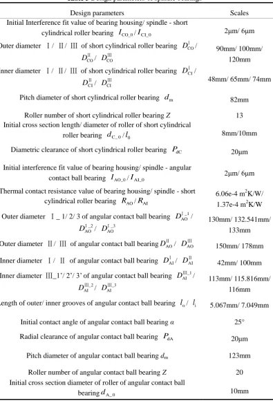
D1/ D2 Inner / outer diameter of rotating ring geometry (m)
P/ P1(2) Compressive stress of rotating ring geometries / onto inner (outer)
cylindrical surface of single rotating ring geometry (Pa)
/
u
Ⅱ_1( 2) _nau
Ⅱ_1( 2) Displacements of outer edge of ring geometry 1 (the inner edge of ringgeometry 2) caused by the rotating ring geometries temperature rise exclusively / mutual compressive stress exclusively (m)
CO(I) AO(I)
/ /
I I I Interference fit value of rotating ring geometries / short cylindrical roller bearing / angular contact ball bearing-bearing housing (spindle shaft) (m) DⅠ/ DⅡ/ DⅢ Diameter Ⅰ/ Ⅱ/ Ⅲ of rotating ring geometries (m)
/
3
by both their temperature rise and mutual compressive stress (m) Z Number of bearing rollers
Ψj / ΔΨ Roller angular position / interval of spindle bearing (rad)
bea bea C / A
Density of short cylindrical roller bearing / angular contact ball bearing (Kg/m3)
bea hou bea hou spi
C A
/ /
E E E Elastic modulus of spindle shaft / short cylindrical roller bearing (its bearing housing) / angular contact ball bearing (its bearing housing) (Pa)
bea hou bea hou spi
C A
/ /
Poisson's ratio of spindle shaft / short cylindrical roller bearing (its bearing housing) / angular contact ball bearing (its bearing housing) bea hou bea hou spi
C A
/ /
Thermal expansion coefficient of spindle shaft / short cylindrical roller bearing (its bearing housing) / angular contact ball bearing (its bearing housing) (℃-1)CO(I)/ AO(I)
P P Compressive stress of outer (inner) ring of short cylindrical roller bearing / angular contact ball bearing (Pa)
l/dC (l/
d
C) Roller axial / radial length (thermal deformation) of short cylindricalroller bearing (m) DⅠCO/ D
Ⅱ
CO/ D
Ⅲ
CO Outer diameter Ⅰ/ Ⅱ/ Ⅲ of short cylindrical roller bearing (m)
DⅠCI/ D
Ⅱ
CI/ D
Ⅲ
CI Inner diameter Ⅰ/ Ⅱ/ Ⅲ of short cylindrical roller bearing (m)
CO/ CI
uⅠ uⅢ Displacement of outer/ inner groove of short cylindrical roller bearing (m)
A
/
Ad
d
Roller diameter length / diameter thermal deformation of angular contact ball bearing (m)i(o)
/
i(o)l
l
Length / length thermal deformation of inner (outer) grooves of angular contact ball bearing (m)DⅠ_iAO, i=1/ 2/ 3 Outer diameter Ⅰ_ 1/ 2/ 3 of angular contact ball bearing (m)
DⅡAO/ D
Ⅲ
AO Outer diameter Ⅱ/ Ⅲ of angular contact ball bearing (m)
DⅠAI/ D
Ⅱ
AI Inner diameter Ⅰ/ Ⅱ of angular contact ball bearing (m)
4 AO, 1/ 2 / 3
i
uⅠ_ i Displacement of inner edge 1/ 2 / 3 of outer ring of angular contact ball bearing (m)
AI , 1'/ 2 '/ 3'
i
uⅢ_ i Displacement of outer edge 1'/ 2'/ 3' of inner ring of angular contact ball bearing (m)
Co(i)j
Q / QAo(i)j Contact stress between jth roller and outer (inner) groove of short
cylindrical roller bearing/ angular contact ball bearing (Pa)
Co(i)j
/ Ao(i)j Radial displacements of outer (inner) groove locations contacted with jth
roller of short cylindrical roller bearing/ angular contact ball bearing (m)
cen C(A)j
F Centrifugal force of jth roller of short cylindrical roller bearing (angular contact ball bearing) (N)
C/ Ao(i)j
K K Contact stiffness between roller and outer (inner) groove of short cylindrical roller bearing / angular contact ball bearing (Pa)
dC(A)
P Diametric clearance of short cylindrical roller bearing/ angular contact ball bearing (m)
dm_C(A) Pitch diameter of short cylindrical roller bearing (angular contact ball
bearing) (m)
C_r
/C_r Relative ring displacement/ thermal variation of relative ringdisplacement of short cylindrical roller bearing (m) FC_r Radial force of short cylindrical roller bearing (N)
nm Roller orbital speed of short cylindrical roller bearing (R/min)
ri(o)/ A Radius/ curvature center distance of inner (outer) grooves of angular
contact ball bearing (m)
uox(y) Curvature center thermal displacement of outer groove of angular contact
ball bearing on X(Y) axis (m)
o(i)
/ j
Initial contact angle / jth roller-outer (inner) groove contact angle of angular contact ball bearing (Rad)
5
MA Bending moment of angular contact ball bearing (Nm) A_r
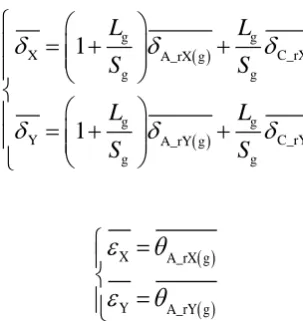
/A_r(A_r g /A_r g ) Radial relative ring displacement/ thermal variation of radial relative ring displacement of angular contact ball bearing (front bearing group) (m)
A_a
/
A_a
(A_a g /A_a g ) Axial relative ring displacement/ thermal variation of axial relative ring
displacement of angular contact ball bearing (front bearing group) (m)
/A_r (A_r g /A_r g ) Angular relative ring displacement/ thermal variation of angular relative
ring displacement of angular contact ball bearing (front bearing group) (Rad)
Bearing contact displacement with the dimension 1
gj
M Gyroscopic moment of jth bearing roller (Nm)
R/ m
Roller geostrophic /orbit velocity of angular contact ball bearing (Rad/s)
J Roller rotary inertia of angular contact ball bearing (Kgm2)
Roller yaw angle of angular contact ball bearing (Rad)
i
Orbit radius of inner groove curvature center of angular contact ballbearing (m)
Fr/Mo/Ba
Q Heat power of spindle front bearings/ motor/ back bearing (W)
Fr/Mo/Ba'
Q Heat power of spindle front bearings/ motor/ back bearing after accurate correction (W)
n Rotating speed of spindle (RPM)
M0 / M1 Bearing frictional torque for lubricant viscosity/applied force load (Nmm)
f0 / f1 Factor related to bearing type and lubrication method / applied force load
ν0 Kinematics viscosity of lubricant (mm2/s)
Fβ Applied force load onto bearing (N)
Dm Mean diameter of the bearing (mm) f/n
h Coefficient of forced/ natural convection heat transfer (W/(m2K)) Nu Nusselt number
6
de / le Diameter / length of the spindle part (m)
Re / Pr Reynolds number / Prandtl number of air uair Flow velocity of air (m/s)
νair Kinematics viscosity of air (m2/s)
TS / Tam Coolant supply / ambient temperature (℃)
VS Coolant supply volume flow rate (L/min)
ρoil_sol /ρoil Coolant oil or solid / solid density (Kg/m3)
koil_sol Thermal conductivity of coolant oil or solid (w/(m·K))
Hen Energy content per unit mass (J)
p Pressure (Pa)
v
/ Velocity vector/ Stress tensor
h
S
Heat energy generated by volumetric heat source (W)u/ v/ w Coolant flowing velocity on X/Y/Z direction (m/s)
( v)
Energy caused by viscous power dissipation of flowing coolant (W)
(k T)
Heat transfer among solid, flowing coolant and ambient air (W)
Q_ Fr/Mo/Ba/
h_ f/nk b k b Proportionality (deviation) correction coefficient for heat generation power/ heat transfer coefficient
Fr/Mo/Ba
T / TFr/Mo/Ba Spindle simulated / experimental temperature (℃)
spi
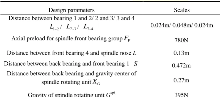
G
Gravity of spindle rotating unit (N)FX\Y\Z Force component of cutting load on X\Y\Z axis (N)
MX\Y Moment component of cutting load about X\Y\Z axis (Nm) P
F Axial preload for spindle front bearing group (N)
1 2
L / L2-3/ L3-4 Distance of bearing 1 - 2/ 2 - 3/ 3 - 4 (m)
L / S/XG Distance of front bearing 4 - spindle nose / back bearing - front bearing 1 /
back bearing - gravity center of spindle rotating unit (m)
X
7
X
/Y Angular thermal error of motorized spindle unit about X/Y axis (rad)
X A / Y A / X B / Y B
Detected values of eddy current displacement sensors X(A)/Y(A)/X(B)/
8
1 Introduction
1Being the key functional component of precision machine tool, the motorized spindle unit has a 2
compact structure combining its built-in motor and spindle bearings. This structure makes the 3
motorized spindle unit have advanced characteristics such as high speed, precision, and rigidity, and 4
thus provide itself with a widespread manufacturing application in recent years. However, the 5
structural characteristic of motorized spindle unit also gives rise to negative effects due to its 6
internal thermal factors on machine comprehensive accuracy [1]. Generally, the internal heat 7
generation and dissipation, mainly from the motor and bearings, of motorized spindle unit 8
determines its structural temperature fluctuation in machining process, and then causes the spindle 9
thermal elastic deformation resulting in the geometric and shape errors of machined workpieces. 10
With growing promotion of precision machining level, thermal deformation of motorized spindle 11
unit has an increasingly obvious disturbance onto machine accuracy and accuracy stability [2]. 12
Therefore, it is essential to study the thermal characteristic mechanism of motorized spindle unit 13
and establish the accurate analyzing and modeling method of spindle thermal error, and these 14
investigations have crucial theoretical and engineering values for the design level improvement of 15
motorized spindle units and the accuracy degeneration avoidance of precision machine tools. 16
Spindle thermal characteristic modeling is the critical basis for spindle thermal error analyses, 17
and various latest research efforts were based on experimental modeling methods to establish the 18
relationship between spindle thermal errors and its other thermal characteristics. Pahk [3] developed 19
a spindle thermal error measuring system, and then used multiple linear regression, neural network 20
and system identification methods respectively to establish spindle temperature - thermal error 21
model. Ko [4] studied experimentally spindle thermal error characteristics in its operation start and 22
stop phases, and found out the relationship between spindle temperature - thermal error measuring. 23
Chen [5] presented an auto-regression dynamic thermal error model with the consideration of the 24
spindle temperature history and speed information. Brecher [6] introduced an indirect spindle 25
thermal error compensation approach, whose model inputs include spindle temperature, rotational 26
speed and motor current values being related to spindle drive torque. Kang [7] adopted forward 27
neural network and hybrid filter methods to predict spindle thermal errors based on its temperature 28
testing, and thus enhanced prediction accuracy and calculation speed. Gomez-Acedo [8] presented an 29
experimentally identified model based on a large gantry-type milling machine. The model inputs are 30
9
thermal drift of the machine tool center point along the 3 axes in different positions within the 1
working volume. In the study of Mayer [9], thermally induced volumetric distortion errors of a 2
five-axis machine tool are modeled in relation to the machine activity sequence during which the 3
power at each of the five axis motors and the spindle are measured. Liu [10] tested radial thermal 4
drift error in Y-direction and temperatures in key points of the spindle of a vertical machining 5
center using its different rotating speeds, for the establishment of radial thermal drift error models 6
under different postures. These experimental modeling activities are of great value onto the 7
recognition about spindle thermal characteristics. Nevertheless, they are lacking in mechanism 8
discussions for spindle thermal errors occurrence, and then difficult to be used to predict and 9
analyze thermal characteristics of motorized spindle unit, during its design and development phase. 10
Some other researching activities placed emphasis on the analytical and simulation modeling 11
methods for the spindle thermal characteristics. Zhao [11] simulated the temperature and thermal 12
error behaviors of a CNC machine tool spindle by FE method, in which the coolant heat transfer is 13
considered approximately as a constant temperature load. Creighton [12] conducted the numerical 14
simulation to get the temperature distribution and thermal growth of a high speed micro milling 15
spindle, with its bearings supporting and motor being considered approximately as main heat 16
sources. Holkup [13] and Li [14] considered the spindle circulating coolant heat transfer as the forced 17
heat convection, and established the thermal-structure coupling simulation model of the high-speed 18
precision spindle to predict and analyze the spindle transient temperature and thermal error 19
characteristics. Jiang [15] used FEM method to analyze spindle temperature distribution, and the 20
variable spindle preload was determined based on bearing temperature rise constraint at high speed 21
range. At low speed range, the spindle preload was resolved by bearing fatigue life. The dynamic 22
stiffness of the variable preload spindle was analyzed utilizing Transfer Matrix Method and a 23
nonlinear bearing model including the centrifugal force and gyroscopic effects. Chen [16] used FEM 24
to simulate the temperature and thermal error behaviors of a hydrostatic spindle unit, with the 25
assumption that the forced convection heat transfer between hydrostatic oil film and the spindle 26
structure is a constant load. Zheng [17] developed a thermal model for high speed press system based 27
on the fractal model and the change of the heat generation power by FE method, to explore its 28
temperature histories and the time for reaching its thermal equilibrium condition. Lee [18] 29
investigated the association between spindle vibration characteristics and thermal errors by an 30
accurate numerical thermal model of motorized spindle unit. Ma [19] established the theoretical 31
10
temperature and thermal error predictions. These studies tried to establish theoretical models to 1
analyze and predict the thermal characteristics of motorized spindle unit. But in these models, there 2
are insufficient influence considerations of bearing thermal characteristic variations on spindle 3
errors, which reduced their prediction accuracy and value in some degrees. 4
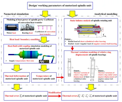
With the emphasis that the spindle thermal errors are closely related to thermal variations of 5
relative ring displacements of spindle bearings, this paper introduces a method to analyze accurately 6
thermal errors of motorized spindle unit. This method is realized by the analytical modeling based 7
on the heat-fluid-solid coupling FE simulation technology. The structure of this paper is arranged as 8
follows: Section 2 introduces thermal-mechanical models of rotating ring geometry and interference 9
assembled rotating ring geometries for theoretical preparations. Then the conclusions of Section 2 10
are applied into thermal variation calculations of relative ring displacements of short cylindrical 11
roller bearing and angular contact ball bearing in Section 3. In Section 4, the obtained thermal 12
variations of bearing relative ring displacements are utilized with the heat-fluid-solid coupling FE 13
simulations for motorized spindle unit, so as to analyze spindle thermal errors. The reliability and 14
accuracy of the developed analytical modeling method for spindle thermal errors is verified by 15
experiments in Section 5. Finally, Section 6 gives the conclusions and prospects of this study. 16
2 Theoretical preparations for thermal modeling of spindle bearings
17This section firstly discusses the thermo-mechanical modeling of a rotating ring geometry, and 18
then its conclusions result in the establishment of a thermo-mechanical displacement model for 19
interference assembled rotating ring geometries. These are necessary theoretical preparations for the 20
thermal variation modeling of relative ring displacements of spindle bearings. 21
2.1 Thermo-mechanical modeling of rotating ring geometry
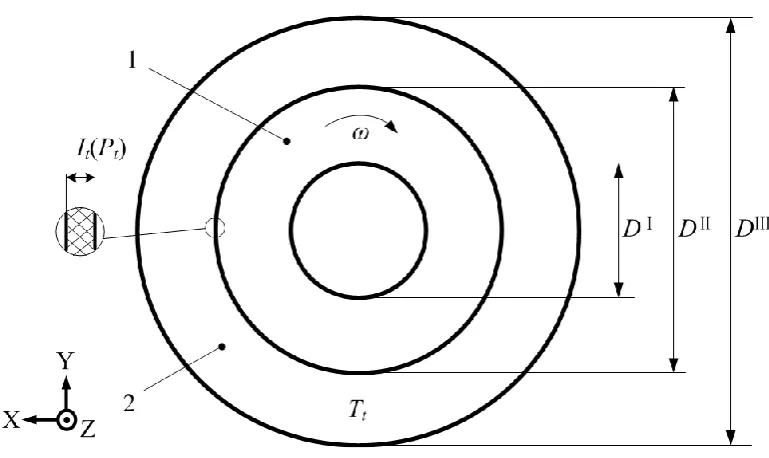
22As depicted in Fig. 1, the presented rotating ring geometry has an angular velocity ω about the Z 23
axis. Its material has the constant properties, and its inner and outer diameters are D1 and D2
24
respectively. Specially, its inner and outer cylindrical surfaces are with the stress P1 and P2
25
respectively. According to the theoretical method about ring geometry introduced in classical book 26
[20]
, the radial displacement of any location of the rotating ring geometry caused by its 27
thermo-mechanical effect can be solved by: 28
11
2 1 1 2 1 2 2S 2 2 S 4 4
0 2 2 2 2 1 1 0 2 1
1 2
2 2
2 2 S 2 2 2 2 3
1 2 2 2
2 1 2 0 2 1
2 2 2 1 2 2 1 3 1
1 d 4 d
32
1 4 3 (1 )
d 32 8 4 D r t t D D D t D r
u T T r D P D P E T T r D D
r E D D
D D E r
P P T T r D D
D E
rE D D
1 2This conclusion give rise to the thermo-mechanical modeling of interference assembled rotating 3
ring geometries. 4
2.2 Thermo-mechanical modeling of interference assembled rotating
5ring geometries
6As depicted in Fig. 2, ring geometries 1 and 2 have inner/ outer diameters DⅠ/ DⅡ and DⅡ/ DⅢ 7
respectively. They are assembled by interference method and have the common angular velocity ω 8
about Z axis. Because the time-varying structural temperature Tt of these rotating ring geometries
9
can lead to their thermal deformations, their interference fit It and compressive stress Pt are
10
influenced by their structural temperature rise Tt - T0.
11
2.2.1 Structural temperature rise - interference compressive stress
12modeling of rotating ring geometries
13If the rotating ring geometries in Fig. 2 is not assembled with interference (without the 14
compressive stress), the outer edge of ring geometry 1 and the inner edge of ring geometry 2 will 15
have the displacements caused by their structural temperature rise Tt - T0 exclusively. These thermal
16
displacements can be seen as the thermal variations of the interference fit scale, when the rotating 17
ring geometries 1 and 2 are assembled together by interference method: 18
19
0
t t t
I I uⅡ_1_nauⅡ_2_na
20
21
Meanwhile, the time-varying interference fit scale can be considered to be the displacement sum 22
caused by the corresponding time-varying mutual compressive stress: 23
24
(1)
12
t t t
I uⅡ_1uⅡ_2
1 2
Equation (3) is substituted into equation (2) to get: 3
4
0
t t t t
uⅡ_1uⅡ_2uⅡ_1_nauⅡ_2_naI
5
6
According to equation (1), the outer edge thermal displacement of ring geometry 1 and the inner 7
edge thermal displacement of ring geometry 2 can be obtained based on the non-assembly state 8
(Ring edge displacements are caused by structural temperature rise Tt - T0 exclusively) and the
9
assembly state (Ring edge displacements are caused by compressive stress exclusively): 10 Non-assembly state: 11
2_1 _1 _1 2
_1
0
2 2 2 2
2 _1 2
2 2 2 2 2 2
_1 _1 _1 _1 _1 _1 _1
_1
_2 2
0
2 2
2 _ 2 2
1 1 1
2 d
3 1 3 1 3 1
64 4 d D t t D D t t D D D
u T T r
D D D D D D
D
D D + D D D
E
D
u T T r
D D
Ⅱ Ⅰ Ⅲ Ⅱ Ⅱ Ⅰ Ⅱ_1_naⅡ Ⅰ Ⅱ Ⅱ Ⅰ Ⅱ
Ⅱ
Ⅱ Ⅰ Ⅰ Ⅱ Ⅱ
Ⅱ Ⅱ_2_na
Ⅱ Ⅲ
_ 2
_ 2
2 _ 2
_ 2
2 _ 2
_ 2
2 2 2 _ 2 2_ 2 1 3 1 3 3 1
64
D
D D D D D
E
Ⅱ
Ⅲ Ⅱ Ⅲ Ⅱ Ⅱ
12 Assembly state: 13
2 _1 2 _1
2 2
_1
_1 2
2 2 2 2 2 2
_1 _1 _1 _1 _1 _1 _1
_1
2 2
_ 2 _ 2
2 2
_ 2
_ 2 2
_ 2 _ 2
_ 2
1 1
2
3 1 3 1 3 1
64 1 1 2 1 3 64 t t t t
D D D
u P
E D D
D
D D + D D D
E
D D D
u P
E D D
D D E
Ⅱ Ⅱ Ⅰ
Ⅱ_1
Ⅰ Ⅱ
Ⅱ
Ⅱ Ⅰ Ⅰ Ⅱ Ⅱ
Ⅱ Ⅱ Ⅲ
Ⅱ_2
Ⅱ Ⅲ
Ⅱ
Ⅲ 2
_ 2
_ 2
2 _ 2
_ 2
2 2 2 _ 2 21 3 D 3 1 D D D
Ⅱ Ⅲ Ⅱ Ⅱ
14
15
(5)
(6)
(4)
13
Equations (5) and (6) are substituted into equation (4) for the interference compressive stress 1
modeling of rotating ring geometries: 2 3
2_1 _1 _1 2 _2 2
_1
0 2 2 2 2 0 2 2 0
2 2
2 2 2 2
_1 _1 _ 2 _ 2
2 2 2 2
_1 _ 2
1 1 1 4
2 d d
1 1 1 1
2 2
D D
t t
D D
t
D D D
I T T r T T r
D D D D D D D D
P
D D D D D D
E D D E D D
Ⅱ Ⅲ Ⅰ ⅡⅡ Ⅰ Ⅱ
Ⅱ Ⅰ Ⅱ Ⅱ Ⅰ Ⅱ Ⅱ Ⅲ
Ⅱ Ⅱ Ⅰ Ⅱ Ⅱ Ⅲ
Ⅰ Ⅱ Ⅱ Ⅲ
4
5
2.2.2 Structural temperature rise - radial displacement modeling of
6no-stress edges of rotating ring geometries
7Radial displacements of the inner edge of ring geometry 1 and the outer edge of ring geometry 2 8
(no-stress edges), which are caused by the comprehensive effect of their structural temperature rise 9
Tt - T0 and interference stress Pt , can be obtained respectively according to equation (1) as well:
10 11
2 _1 2 02 2 _1 2 2
2 _1 2
2 2 2 2 2 2
_1 _1 _1 _1 _1 _1 _1
_1 4
d
3 1 3 1 1 3
64
D
t t t
D
D D D
u T T r + P
D D E D D
D
D D D D D
E
Ⅱ Ⅰ Ⅰ Ⅱ Ⅰ ⅠⅠ Ⅱ Ⅰ Ⅱ
Ⅰ
Ⅱ Ⅰ Ⅱ Ⅰ Ⅰ
12 13
2 2_ 2 _ 2 _ 2 2 _2
0 2 2
2 2 2 2
_ 2 2
_ 2 2
2 2 2 2 2 2
_ 2 _ 2 _ 2 _ 2 _ 2 _ 2 _ 2 _ 2
1 1 1
2 d
1 3 1 3 3 1
64
D
t t t
D
D D D D
u T T r P
D D D D D D E D D
D
D D D D D
E
Ⅲ ⅡⅡ Ⅲ Ⅲ Ⅱ
Ⅲ
Ⅲ Ⅲ Ⅱ Ⅲ Ⅱ Ⅲ Ⅱ Ⅲ
Ⅲ
Ⅱ Ⅲ Ⅱ Ⅲ Ⅲ
14
15
In equations (8) and (9), Pt must be calculated according to the equation (7). Then these
16
conclusions can be the theoretical guidance for the thermal displacement calculations of outer 17
groove (inner edge of outer ring) and inner groove (outer edge of inner ring) of both the short 18
cylindrical roller bearing and angular contact ball bearing in Section 3. 19
(7)
(9)
14
3 Thermal variation modeling of relative ring displacement of typical
1spindle bearings
2Based on the theoretical preparations in Section 2, this section investigates the thermal variation 3
modeling methods of relative ring displacements of short cylindrical roller bearings and angular 4
contact ball bearing. This section introduces the basis for the thermal errors modeling of motorized 5
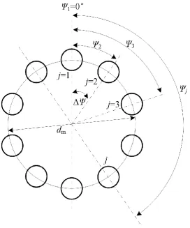
spindle unit in Section 4. To facilitate theoretical analyses in this section, relative angular locations 6
of rollers in a common bearing structure are defined in Fig. 3. The angular position of each bearing 7
roller and the angular interval between any two neighboring rollers respectively are: 8
9
2 ( 1)
2
j
j Z
Z
10
11
3.1 Thermal variation modeling of relative ring displacement of short
12cylindrical roller bearing
13Fig. 4 (a) shows the structural and assembly conditions of the short cylindrical roller bearing: The 14
bearing outer ring has concerned diameters DⅠCO/ DⅡCO/ DⅢCO, and there is an interference fit ICO
15
between the outer ring and bearing housing. Similarly, the bearing inner ring has concerned 16
diameters DⅠCI/ D
Ⅱ
CI/ D
Ⅲ
CI, and there is an interference fit ICI between the inner ring and shaft. The
17
short cylindrical roller has the dC diameter and l length. On the other hand, as shown in Fig. 4 (b),
18
the short cylindrical roller bearing, operating at an angular velocity ω, will has the radial 19
displacement δC_r, when it is influenced by a radial load FC_r. Because the short cylindrical roller
20
bearing is designed to allow the relative axial movement between its inner and outer ring to some 21
extent, its load and relative ring displacement on radial direction are considered exclusively. When 22
the short cylindrical roller bearing has a structural temperature rise TC_t-T0, all of its parts will have
23
thermal deformations causing thermal variation of its relative ring displacement. Therefore, thermal 24
deformations of bearing rollers and the thermal displacements of bearing grooves must be analyzed. 25
15
3.1.1 Roller thermal deformation modeling of short cylindrical roller
1bearing
2Thermal deformation calculation methods of the roller, in Fig. 4 (a), of the short cylindrical roller 3
bearing can be described respectively as follows: 4
5
bea
C 0 C_ 0
bea
C C C 0 C_ 0
t t
_t _ t
l l T T
d d T T
6 7
3.1.2 Groove thermal displacement modeling of short cylindrical roller
8bearing
9As illustrated in Fig.4 (a), for the structure of short cylindrical roller bearing, the rollers are 10
contacted with the outer groove (inner edge of outer ring) and inner groove (outer edge of inner 11
ring). Because outer ring - bearing housing and inner ring - spindle shaft are assembled by 12
interference methods respectively, the thermal displacements of the bearing grooves can be 13
calculated based on the thermo-mechanical model of the interference assembled rotating ring 14
geometries in Section 2. For the static outer groove, its thermal displacement is calculated based on 15
ω=0, and it must be determined according to equation (8): 16 17
CO CO 2 bea 2 CO CO C COCO_ 2 2 C_ 0 bea 2 2 CO _
CO CO C CO CO
2 4
d
D
t t t
D
D D
D
u T T + P
D D E D D
Ⅱ Ⅰ Ⅰ Ⅱ Ⅰ ⅠⅠ Ⅱ Ⅰ Ⅱ
18
19
In equation (12), PCO _t is:
20 21
CO CO CO CO 2bea bea bea 2 hou 2
C CO C CO C
bea C CO
CO_0 C 2 2 2 2 C_ 0 2 2 C_ 0
CO CO CO CO CO
CO CO CO
2 2
CO _ 2 bea 2 bea
CO CO C CO C
be C
1 1 1 4
2 d d
1 1 2 D D t t D D t
D D D
I T T T T
D D D D D D D D
P
D D D
E
Ⅱ Ⅲ Ⅰ ⅡⅡ Ⅰ Ⅱ
Ⅱ Ⅰ Ⅱ Ⅱ Ⅱ
Ⅱ Ⅰ Ⅱ
Ⅱ Ⅱ Ⅰ
2 hou 2 hou
CO CO C CO C
2 2 2 2
a hou
CO CO C CO CO
1 1
2
D D D
D D E D D
Ⅱ Ⅱ Ⅲ
Ⅰ Ⅱ Ⅱ Ⅲ
22
(11)
(12)
16
Unlike the outer ring, the thermal displacement of rotating inner groove can be determined 1
according to equation (9): 2 3
CI CI 2bea 2 bea bea 2
C CI C CI C CI CI
bea
CI_ C 2 2 2 2 C_ 0 bea 2 2 CI _
CI CI CI CI CI CI C CI CI
2 bea 2
2
bea bea bea
C CI
C C CI C C
bea C
1 1 1
2 d
1 3 1 3
64
D
t t t
D
D D D D
u T T P
D D D D D D E D D
D D E
Ⅲ ⅡⅡ Ⅲ Ⅲ Ⅱ
Ⅲ
Ⅲ Ⅱ Ⅲ
Ⅲ Ⅱ Ⅲ Ⅱ Ⅲ
Ⅲ
Ⅱ
bea
2 2 bea
bea
2 2 bea 2CI CI 3 C 1 C CI CI C
D D D D
Ⅲ Ⅱ Ⅲ Ⅲ
4
5
In equation (14), PCI _t is:
6 7
CI CI CI CI 2spi spi spi 2 bea 2
CI CI
spi C CI
CI_0 2 2 2 2 C_ 0 2 2 C_ 0
CI CI CI CI CI
CI CI CI
2 2
CI _ 2 2
spi spi
CI CI CI
2 spi
CI
1 1 1 4
2 d d
1 1 2 D D t t D D t
D D D
I T T T T
D D D D D D D D
P
D D D
E D
Ⅱ Ⅲ Ⅰ ⅡⅡ Ⅰ Ⅱ
Ⅱ Ⅰ Ⅱ Ⅱ Ⅰ Ⅱ Ⅱ Ⅲ
Ⅱ Ⅱ Ⅰ
Ⅰ
2 2
bea bea
CI CI C CI C
2 bea 2 2
CI C CI CI
1 1
2
D D D
D E D D
Ⅱ Ⅱ Ⅲ
Ⅱ Ⅱ Ⅲ
8
9
3.1.3 Thermal variation modeling of relative ring displacement of
10short cylindrical roller bearing
11Models of thermal deformations of bearing rollers and the thermal displacements of bearing 12
grooves can be adopted to analyze the thermal variation of relative ring displacement of short 13
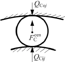
cylindrical roller bearing. When the operating short cylindrical roller bearing is under a radial force 14
FC_r shown in Fig. 4 (b), the force balance relationship of the jth cylindrical roller of the bearing at
15
moment t is shown in Fig. 5. According to the theoretical method about short cylindrical roller 16
bearing in classical book [21], the force balance equation of operating short cylindrical roller bearing 17 can be: 18 19
10 C_ 9 Ci _ 8 4 1 9 0 cos 0 8.05 10 j Z rj t j j t F l l
20 21(16) (14)
17
Besides, the force balance equation of jth cylindrical roller of the bearing can be: 1
10
cen 10
9
dC _ 0 CO_ CI_ C_ 9 C _
Cr _ Ci _ Ci 8
4
9 0
2 2
cos 0
2
8.05 10
t t t j t
t j j t j_t
t
P u u d F
l l
Ⅰ Ⅲ
2
3
In equation (17), dC_t/lt must be calculated according to equations (11), and uCO_t
Ⅰ
/uCI_t
Ⅲ
are 4
determined by equations (12) and (14) respectively. The roller centrifugal force FC _cenj t should be 5
calculated by the method: 6
7
2
cen 11 2
C _j t 3.39 10 C 0_ C_t 0 t m_C m
F d d l l d n 8
9
The solution of simultaneous equations (16) and (17) are solved by Newton - Raphson method 10
for
Cr _t. After solutions, the variation of relative ring displacement of short cylindrical roller11
bearing due to its temperature rise TC_t T0 has to be calculated by the following method:
12 13
C _ 0
C_r Cr _ Cr _ 0
t t
T T
14
15
3.2 Thermal variation modeling of relative ring displacement of
16angular contact ball bearing
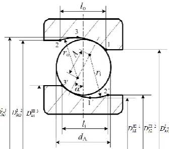
17The structural and assembly conditions of angular contact ball bearing are almost similar with 18
short cylindrical roller bearing. As depicted in Fig. 6 (a), the bearing outer ring has concerned 19
diameters DⅠAO/ DⅡAO/ DⅢAO, and there is an interference fit IAO between the outer ring and
20
bearing housing. The bearing inner ring has concerned diameters DⅠAI/ DⅡAI/ DⅢAI, and there is an
21
interference fit IAI between the inner ring and spindle shaft. Besides, Fig. 6 (b) shows some detail
22
bearing parameters for the ball roller - bearing ring contacts: The diameter of the ball roller is dA.
23
The bearing inner and outer ring has the groove length/ radius li/ ri and lo/ ro respectively. The
24
angular contact ball bearing without external load has the initial contact angle α. The central 25
distance between outer and inner grooves is A. Specially, the scales of DⅠAO and DⅢAI in Fig. 6 (a)
26
(17)
(19)
18
must be analyzed in detail to be 6 bearing diameters (DⅠ_iAO and DⅢ_iAI, i=1,2,3) in Fig. 6 (b). The
1
locations 3 and 1’ are the deepest positions of outer and inner grooves respectively. Fig. 6 (c) 2
reveals the bearing load and displacement conditions: Generally, the angular contact ball bearing, 3
operating at an angular velocity ω, will have the radial displacement δA_r /axial displacement δA_a
4
/angular displacement θ, which are caused by the bearing radial load FA_r /axial load FA_a /torque
5
MA respectively. When the angular contact ball bearing has a structural temperature rise TA_t-T0, all
6
the bearing parts will have thermal deformations, and then causes the thermal variations of its 7
radial/ axial/ angular relative ring displacement. Therefore, thermal deformations of bearing rollers 8
and thermal displacements of bearing grooves must be calculated. 9
3.2.1 Roller thermal deformation modeling of angular contact ball
10bearing
11As depicted in Fig. 6 (a), the roller of angular contact ball bearing is contacted with its outer and 12
inner groove. Then the thermal deformation of outer/ inner groove width and ball roller diameter, 13
shown in Fig. 6 (b), can be calculated respectively as follows: 14
15
bea
o(i) _t A o(i) _ 0 A_t 0
l l T T
16
17
bea
A_t A A 0_ A_t 0
d d T T
18
19
3.2.2 Groove thermal displacement modeling of angular contact ball
20bearing
21Being similar with the short cylindrical roller bearing, angular contact ball bearing has 2 part 22
pairs assembled by interference method respectively: outer ring - bearing housing and inner ring - 23
spindle shaft, which is shown in Fig. 6 (a). The rollers are contacted with the outer groove (inner 24
edge of outer ring) and inner groove (outer edge of inner ring). The thermal displacements of 25
bearing groove positions can be gained by thermo-mechanical model of the interference assembled 26
rotating ring geometries in Section 2. According to equation (8), thermal displacements of positions 27
1, 2, 3 of static outer groove, shown in Fig. 6 (b), caused by temperature rise TA_t-T0 of angular
28
contact ball bearing can be calculated based on ω=0: 29
(21)
19 1
AO AO _ 2 bea 2 AO AO A AOAO_ 2 2 A_ 0 bea 2 2 AO _
AO AO A AO AO
2 _ _ _ _ _ 4
d , 1, 2,3
i i i i t i i D t t D D D D
u T T + P i
D D E D D
Ⅱ Ⅰ Ⅰ Ⅱ Ⅰ ⅠⅠ Ⅱ Ⅰ Ⅱ
2
3
In equation (22), PAO _t is:
4 5
AO AO AO _ AO 2bea bea bea 2 hou 2
A AO A AO A
bea A AO
AO_0 A 2 2 2 2 A_ 0 2 2 A_ 0
AO
AO AO AO AO AO AO AO
2 2
AO _ 2 2
bea bea
AO AO A AO A
_
_ _
_
1 1 1 4
2 d d
1 1
i
D D
t i
i i t
D D
t
i
D D D
I T T r T T r
D D D D D D D D
P
D D D
Ⅱ Ⅲ Ⅰ ⅡⅡ Ⅰ Ⅱ
Ⅱ Ⅰ Ⅱ Ⅱ Ⅲ
Ⅱ Ⅰ Ⅱ
Ⅱ Ⅱ Ⅰ
2 2
hou hou
AO AO A AO A
2 2 2 2
bea hou
A AO AO A A
_
O AO
1 1
2 2
, 1, 2,3
i
D D D
E D D E D D
i
Ⅱ Ⅱ Ⅲ
Ⅰ Ⅱ Ⅱ Ⅲ
6
7
Meanwhile, thermal displacements of positions 1', 2', 3' of rotating inner groove in Fig. 6 (b) can 8
be gained according to equation (9) as well: 9 10
AI A _ I 2 2bea bea bea 2
A AI A AI A AI AI
bea
AI_ A 2 2 2 2 A_ 0 bea 2 2 AI _
AI AI AI
_ _
_
_ _
_
AI AI AI A AI AI
2 bea 2 bea A AI A A bea _ _ _ A
1 1 1
2 d 1 3 64 i D t i i i i i D
i i t i
i
t
D D D D
u T T r P
D D D D D D E D D
D E
Ⅲ ⅡⅡ Ⅲ Ⅲ Ⅱ
Ⅲ
Ⅲ Ⅲ Ⅱ Ⅲ Ⅱ Ⅲ Ⅱ Ⅲ
Ⅲ
bea
2 bea
bea
2 2 bea
bea
2 2 bea 2AI A A AI AI A
_ _
A AI AI A
_
1 3 3 1
, 1', 2 ',3'
i i i
D D D D D
i
Ⅱ Ⅲ Ⅱ Ⅲ Ⅲ
11
12
In equation (24), PAI _t is:
13 14
AI AI AI AI _ 2spi spi spi 2 bea 2
AI AI
spi A AI
AI_0 2 2 2 2 A_ 0 2 2 A_ 0
AI AI AI AI AI
AI AI AI
2 2
AI _ 2 spi 2 spi
AI AI AI
spi A
_
1 1 1 4
2 d d
1 1 2 i D D i t t D D t
D D D
I T T r T T r
D D D D D D D D
P
D D D
E D
Ⅲ Ⅱ Ⅰ ⅡⅡ Ⅰ Ⅱ
Ⅱ Ⅰ Ⅱ Ⅱ Ⅰ Ⅱ Ⅱ Ⅲ
Ⅱ Ⅱ Ⅰ
2 bea 2 bea
AI AI A AI A
2
_
_
2 2 2
bea
I AI A AI AI
1 1
2
, 1', 2 ',3'
i
i
D D D
D E D D
i
Ⅱ Ⅱ Ⅲ
Ⅰ Ⅱ Ⅱ Ⅲ
15
16
(22)
(23)
(24)
20
3.2.3 Thermal variation modeling of initial contact angle of angular
1contact ball bearing
2The roller thermal deformation and groove thermal displacement models can be used to analyze 3
the thermal variation of initial contact angle of angular contact ball bearing. If an angular contact 4
ball bearing without external load has a structural temperature rise TA_t-T0, the thermal drifts of
5
bearing groove radii and ball roller diameters will cause the thermal variation of bearing initial 6
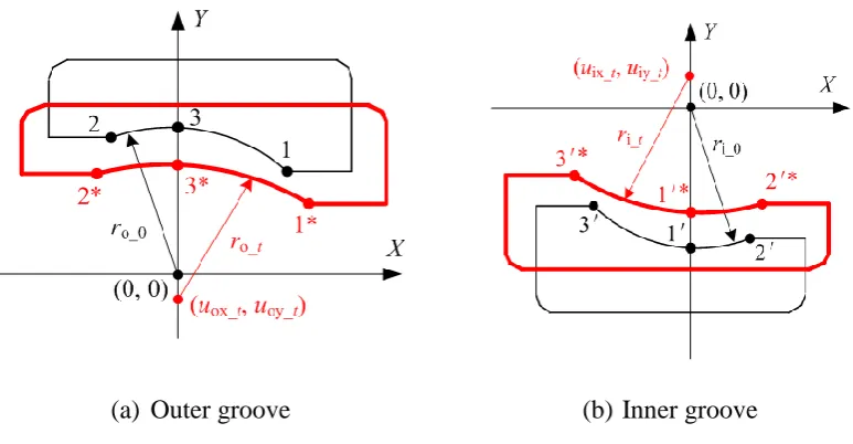
contact angle, and then cause the relative ring displacements of angular contact ball bearing. As 7
demonstrated in Fig. 7(a) and (b), the curvature centers of bearing inner and outer grooves are 8
placed onto the origin of coordinate system respectively. The bearing structural temperature change 9
TA_t-T0 leads to its contour thermal variation of inner and outer rings and center thermal shift of
10
bearing grooves. The coordinates of initial positions 1, 2, 3 of bearing outer groove in Fig. 7 (a) 11
meet a relationship: 12
13
2 2 2
o _ 0
x y r 14
15
Then varying locations of these 3 positions (1*, 2*, 3*), owing to the groove thermal drift, meet: 16
17
2ox _t oy _t o _t
x u
y u
r
18
19
Then the coordinate transformations from positions 1, 2, 3 to 1*, 2*, 3* can be: 20
21
o _* * _ _ AO_
2
_
1
,
,
i t,
1, 2,3
i i i xi t i yi t i i
i t
x l
x y
x
u
y
u
x
y
u
,i =
x
x
Ⅰ 22
23
In equation (28), Δlo_t and
_ AO_t
i
uⅠ (i=1, 2, 3) must be obtained according to equations (20) and (22) 24
respectively. Then equation (28) is substituted into (27), and can be simultaneous with equation (26) 25
to solve ro_t. By the same method, ri_t in Fig. 7 (b) can also be gained. Based on these preparations,
26
the initial contact angle of angular contact ball bearing can be obtained according to geometry 27
relationship in Fig. 6 (b). By the method introduced in classical book [21], the initial contact angle of 28
angular contact ball bearing can be modeled to be associated with thermal factors: 29
(26)
(27)
21
1
_3 _1 _3 _1
AO AI AO_ AI_ A_0 A_
1
o_ i_ A_0 A_
2 cos 1
2
t t t
t
t t t
D D u u d d
r r d d
Ⅰ Ⅲ Ⅰ Ⅲ
2
3
In equation (29), dA_t,
_ AO_
3
t
uⅠ and uAI_Ⅲ_t1 must be obtained by equations (21), (22) and (24) 4
respectively. 5
3.2.4 Thermal variation modeling of relative ring axial/ radial/
6angular displacements of angular contact ball bearing
7On the basis of thermal variation modeling of initial contact angle of angular contact ball bearing, 8
the thermal variation model of relative ring axial/ radial/ angular displacements of angular contact 9
ball bearing can be established based on its defined external axial, radial and angular loads. When 10
the angular contact ball bearing in Fig. 6 (c) is operating with its axial load FA_a, radial load FA_r and
11
torque MA, the position relationship of roller center and curvature centers of bearing outer and inner
12
grooves will be different from its no-load condition. 13
As illustrated in Fig. 8, for jth bearing ball roller, the connecting line of inner and outer ring 14
groove centers is collinear with BdA(A) at no-load condition. However, when the angular contact
15
ball bearing is operating with external loads, the connecting line above is no longer collinear with 16
BdA(A). This is because the roller centrifugal force results in the contact angle change of angular
17
contact ball bearing. Since the bearing outer ring is generally considered to be fixed in motorized 18
spindle unit, both the curvature center of bearing inner groove and the center of ball roller center are 19
considered to have relative movements to the curvature center of bearing outer groove. By the 20
method introduced in classical book [21], firstly, the geometry relationships in Fig. 8 can be 21
summarized as follows: 22
23
2
2 2
i_ o_ A_0 A Aa_ i 1 _ 2 _ 2 _ i_ A_0 A Ai
2
2 2
1 _ 2 _ o_ A_0 A Ao
1
sin cos 0
2 1
0 2
t t _t t t t j j t j t j t t _t j_t
j t j t t _t j_t
r r d d X A X r d d
X X r d d
24
25
(29)