© 2019, IRJET | Impact Factor value: 7.211 | ISO 9001:2008 Certified Journal | Page 5938
Analysis of LVRT Capability of Grid Connected Solar Photovoltaic
System
Jenitha. J
1, R. Rajeswari
21
M.E II
Year, Department of EEE, Government College of Technology, Coimbatore, India.
2Associate Professor, Department of EEE, Government College of Technology ,Coimbatore, India.
---***---Abstract -
The penetration of Distributed Generation (DG)
sources such as Photovoltaic (PV) power plants are becoming more prominent in the electric grid due to the incremental demands for electrical energy. However, fault condition in the grid, not only can cause the disconnection of grid connected PV systems but also disturb the stability of the main grid and can cause detrimental influence on the availability and reliability of the whole system. Due to this, many countries have established grid code requirements for grid connected PV system that should be met. Hence a control strategy has been proposed in this paper in accordance with the grid code requirements, in order to withstand the low voltage condition in the grid. Therefore the widespread loss of generation can be avoided to a great extent. The functionality of proposed control strategy is verified using Matlab/Simulink environment under unbalanced fault in the standard IEEE power system.
Key Words: PV system, low voltage ride through, IEEE
system, unbalanced faults.
1. INTRODUCTION
Advancement in Power electronics has lead to the large scale integration of renewable energy systems with electric power distribution network. Though integration of Renewable Energy Sources (RES) is an inevitable operation in the electric grids, such integration of renewable energy sources such as Photovoltaic (PV) system to the conventional electric grid infrastructure is a challenging task, due to their intermittent nature of electric power generation. And the challenge includes the disconnection of PV system from the grid under fault condition, which further leads to instability in the grid integrated photovoltaic system and results in system wide power outages.
With the significant share of power produced by the distributed generation system such as solar energy sources, the grid code standards for connecting these sources to the electric grid have been updated. These standards enforce that the Photovoltaic system must stay connected to the grid even under fault conditions in short periods and must help the grid to come back to normal conditions. This ability of the system to stay connected to the grid during fault condition is known as Low Voltage Ride Through (LVRT) .The significance of LVRT is analyzed by introducing fault in the individual buses
of the system and the voltage of near and far end buses of the system is analyzed during fault condition.
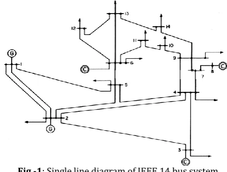
2. IEEE 14 BUS SYSTEM
In an interconnected power system, the buses are connected either with one device or a combination of devices like generators, loads and voltage control equipments. Each bus in the power system is associated with four quantities, bus voltage magnitude, phase angle, real power and reactive power. In a load flow solution two out of four quantities are specified and the remaining two are required to be obtained through the solution of the equations. Depending on which the quantities have been specified, the buses are classified into three categories such as Generator bus, load bus, swing bus. Totally there are five generators and nine loads in the IEEE 14 bus system. The single line diagram of IEEE 14 bus system is depicted in the figure 1.
Fig -1: Single line diagram of IEEE 14 bus system The minimum and maximum limits of voltage magnitude and phase angle are considered to be 0.95 pu to 1.05 pu and -45° to +-45° respectively.
[image:1.595.320.553.441.618.2]© 2019, IRJET | Impact Factor value: 7.211 | ISO 9001:2008 Certified Journal | Page 5939
Table -1: Bus data of IEEE 14 bus systemBus No Voltage Magnitude (pu)
1 1.06
2 1.045
3 1.01
4 1
5 1
6 1.07
7 1
8 1.09
9 1
10 1
11 1
12 1
13 1
14 1
According to the values obtained from the bus data and by taking the single line diagram as reference the IEEE 14 bus system is simulated.
3. LVRT CONTROL APPROACH
The control of the system can be divided into two main parts, boost converter control as shown in Fig.2 and grid tied inverter control.
3.1 Control of the Boost Converter
The schematic of the boost converter power stage is shown in fig. 2. It consists of the power switch (IGBT), inductor, output diode D and filter capacitor C.
In the continuous conduction mode, when the switch of
the converter is in the on state, the current in the inductor increases linearly, and at that moment, the diode is in the off state. When the switch is turned off, the energy stored in the inductor is discharged through the diode to the DC link [4]. The switching action will produce a pulsating current. The capacitive filter will smoothen it and provide a DC voltage to the inverter.Fig -2: Boost Converter Control Diagram
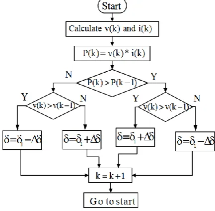
In this paper, the Perturb and Observe (P and O) Technique is used to track the point of maximum power as shown in Fig.3.
Fig -3: Flow Chart of P and O Algorithm
In this technique, the Maximum Power is calculated based on the measurements of the Temperature and the Irradiance of the PV panel used in the system [5].
[image:2.595.45.278.119.368.2] [image:2.595.323.540.309.521.2]© 2019, IRJET | Impact Factor value: 7.211 | ISO 9001:2008 Certified Journal | Page 5940
3.2 LVRT Control System
The three phase, two stage grid interfaced photovoltaic system is composed of a boost converter and a three phase inverter. The grid code requirements for grid connected photovoltaic systems should be met and these requirements impose that the photovoltaic power generating plants should stay connected to the grid in case of voltage sag, which is usually caused by grid faults. This ability is known as Low Voltage Ride Through (LVRT) capability.
Fig -4: Block diagram of LVRT control strategy for grid connected PV system
The block diagram of the low voltage ride through control strategy of grid connected PV system is depicted in the Fig.4. The voltage and current from the grid and the inverter is taken as the reference for generating the control signal for the grid connected photovoltaic inverter. The voltagefrom the grid and theinverter voltage are synchronized by the use of Phase Locked Loop (PLL).Thus by controlling the pulse given to the PV inverter connected to the grid, the low voltage ride through operation can be obtained [1].
The voltage from the grid and the inverter voltage are synchronized by the use of Phase Locked Loop (PLL). Thus by controlling the pulse given to the PV inverter connected to the grid, the low voltage ride through operation can be obtained. PLL is a control system that generates an output signal whose phase is related to the phase of an input signal, it consists of a variable frequency oscillator and a phase detector in a feedback loop.
5. SIMULATION RESULTS
Simulation is developed in MATLAB/SIMULINK platform
to verify the effectiveness of the proposed control scheme. The three phase grid connected PV system is simulated under unbalanced fault in the grid. The PV panel output voltage is shown in Fig.5. The voltage of the photovoltaic module is measured under standard test conditions (STC) of1000W/m2 solar irradiance and 25°C PV module
temperature.
Since the output from the PV module is not sufficient for feeding into the electrical grid directly, it is stepped up by using a (dc-dc) boost converter. The boost converter is connected to the three phase inverter via a dc link capacitor.
Fig -5: PV Panel output voltage
The output voltage of the PV module is a constant dc of
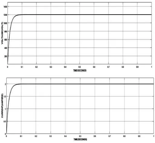
magnitude 400V.Fig -6: Boost Converter output voltage, Current
The output voltage obtained from the boost converter is 1200V and its output current is 2A as depicted in the fig.6.
[image:3.595.314.570.198.361.2] [image:3.595.33.278.226.407.2] [image:3.595.312.569.439.675.2]© 2019, IRJET | Impact Factor value: 7.211 | ISO 9001:2008 Certified Journal | Page 5941
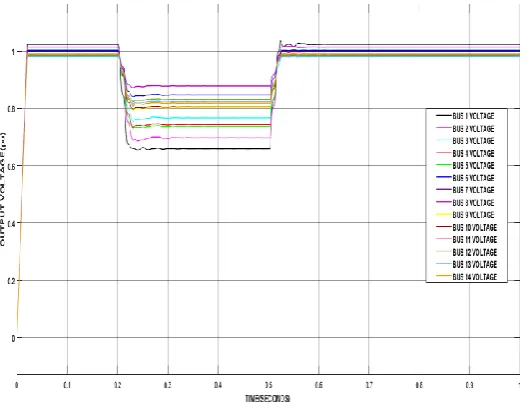
near and far end buses of the PV system is analyzed [11].Initially the fault is simulated in the bus 4 i.e., to the near end bus of the PV system and the voltage of the IEEE 14 bus system is analyzed as shown in the fig.7. The voltage of the IEEE 14 bus system is simulated in terms of per unit (pu) value in other words its simulated in terms of magnitude rather than nominal value for obtaining simplified analysis of the system.
Fig -7: Output voltage under fault at bus 4
[image:4.595.314.572.131.306.2]The fault is simulated for a very short duration of (0.2-0.5) seconds i.e., 300msec. It is observed that the severity of voltage dip is severe in the bus in which the fault is located when compared to the far end buses and the photovoltaic system is able to retain its nominal voltage once the fault is cleared.
Fig -8: Output Voltage under fault at bus 1
Similarly the fault is simulated in the far end buses of the PV system such as bus 1 and bus 13 as shown in fig. 8,9 and its voltage is analyzed. And it is observed the voltage dip is
prominent in the bus1,13 at which the fault is simulated when compared to far end buses.
Fig-9: Output Voltage under fault at bus 13
Thus it is inferred that the system is able to ride through the low voltage for a short period of time as specified by the Indian grid code standard [2].
3. CONCLUSION
The analysis of Low Voltage Ride Through (LVRT) capability of the grid connected solar photovoltaic system is carried out. From the results provided by the performed MATLAB simulations, under unbalanced faults it is observed that the voltage dip is prominent in the buses nearer to the location of fault than the far end buses. And the photovoltaic system is able to withstand the low voltage for short period of time as specified by the Indian grid code standard, indicating that the photovoltaic system stays connected to the grid during the fault condition, providing low voltage ride through of the photovoltaic system.
REFERENCES
[1] Hasanien, H. M., 2016, “An Adaptive Control Strategy for
Low Voltage Ride Through Capability Enhancement of Grid-Connected Photovoltaic Power Plants”, IEEE Transactions on Power Systems, 31,No.4,pp. 3230–3237.
[2] Ehsan Afshari, Babak Farhangi, Yongheng Yang,
Shahrokh Farhangi, 2017, “ A Low-Voltage Ride-Through Control Strategy for Three-Phase Grid-Connected PV Systems”, IEEE Transactions on Power Electronics., 31,No.6, pp.4182–4194.
[3] Steve Gehl, 2003, “Electricity Technology Roadmap
Summary and Synthesis”, Technical Report, Electric Power Research Institute.
[4] Tasi-Fu Wu And Yu-Kai Chen,2012, “Modeling PWM
[image:4.595.20.290.205.377.2] [image:4.595.25.289.487.688.2]© 2019, IRJET | Impact Factor value: 7.211 | ISO 9001:2008 Certified Journal | Page 5942
Transactions On Power Electronics”,13,No. 5,pp. 870–881.
[5] Esram, T., and Chapman, P. L. ,2007, “Comparison of
Photovoltaic Array Maximum Power Point Tracking Techniques”, IEEE Transactions on Energy Conversion, 22,No.2, pp.439–449.
[6] Guo, X., Zhang, X., Wang, B., Wu, W., & Guerrero, J.
M.,2014, “Asymmetrical Grid Fault Ride-Through Strategy of Three-Phase Grid-Connected Inverter Considering Network Impedance Impact in Low- Voltage Grid”, IEEE Transaction on Power Electronics,29,No.3,pp.1064-1068.
[7] P. Giroux, G. Sybille, 2012, “100-kW Grid-Connected PV
Array Demo Detailed Model”, Math Works File Exchange, Hydro-Quebec Research Institute (IREQ).
[8] I. V. Banu, R. Beniuga and M. Istrate, 2013, “Comparative
Analysis of the Perturb and Observe and Incremental Conductance MPPT Methods”, Proceedings of the International Symposium on Advanced Topics in Electrical Engineering (ATEE), pp. 1-4.
[9] Karanayil, B., Agelidis, V. G., & Pou, J., 2014,
“Performance Evaluation of Three-Phase Grid Connected Photovoltaic Inverters Using Electrolytic or Polypropylene Film Capacitors”, IEEE Transactions on Sustainable Energy, 5,No.4,pp. 1297–1306.
[10] Anurag, A., Deshmukh, N., Maguluri, A., & Anand, S.,
2018, “Integrated DC–DC Converter Based Grid-Connected Transformerless Photovoltaic Inverter With Extended Input Voltage Range”, IEEE Transactions on Power Electronics, 33,No.10, pp. 822–830.
[11] F. A. Neves, M. Carrasco, F. Mancilla-David, G. M.
Azevedo, and V. S. Santos, "Unbalanced Grid Fault Ride-Through Control for Single-Stage Photovoltaic Inverters," IEEE Transactions on Power Electronics, vol. 31, no. 4, pp. 3338-3347, 2016.
[12] H. C. Chen, C. T. Lee, P. T. Cheng, R. Teodorescu, and F.
Blaabjerg, "A Low-Voltage Ride-Through Technique for Grid-Connected Converters With Reduced Power Transistors Stress," IEEE Transactions on Power Electronics, vol. 31, no. 12, pp. 8562-8571, 2016.
[13] E. Afshari, G. R. Moradi, Y. Yang, B. Farhangi, and S.
Farhangi, "A Review on Current Reference Calculation of Three-Phase GridConnected PV Converters under Grid Faults," presented at the IEEE Power and Energy Conference at Illinois (PECI), Illinois, USA, 2017.
[14] A. Petucco, P. Mattavelli, A. Zuccato, and A. Abdelhakim,
"Low-voltage ride through (LVRT) testing of full power converter for wind turbines using all-electronic equipment," in 8th IET International Conference on Power Electronics, Machines and Drives (PEMD 2016), 2016, pp. 1-6.
[15] R. Teodorescu and M. Liserre, Grid converters for
photovoltaic and wind power systems vol. 29: John Wiley & Sons, 2011.
[16] P. Rodriguez, A. V. Timbus, R. Teodorescu, M. Liserre,
and F. Blaabjerg, "Flexible active power control of distributed power generation systems during grid
faults," IEEE Transactions on Industrial Electronics, vol. 54, no. 5, pp. 2583-2592, 2007.
[17] A. Junyent-Ferre, O. Gomis-Bellmunt, T. C. Green, and D.
E. SotoSanchez, "Current control reference calculation issues for the operation of renewable source grid interface VSCs under unbalanced voltage sags," IEEE Transactions on Power Electronics, vol. 26, no. 12, pp. 3744-3753, 2011.
[18] M. Amirabadi, A. Balakrishnan, H. A. Toliyat, and W. C.
Alexander, "High-Frequency AC-Link PV Inverter," IEEE Transactions on Industrial Electronics, vol. 61, no. 1, pp. 281-291, 2014.
[19] M. Khodabandeh, M. R. Zolghadri, M. Shahbazi, and N.