Operating Nanobeams in a Quantum Fluid: Probing
the Condensate and Cooling the Beam
D. I. Bradley, R. George, A. M. Gu ´enault, R. P. Haley, S. Kafanov
∗, M. T. Noble,
Yu. A. Pashkin, G. R. Pickett, M. Poole, J. R. Prance, M. Sarsby, R. Schanen, V. Tsepelin
†,
T. Wilcox, and D. E. Zmeev
Department of Physics, Lancaster University, Lancaster, LA1 4YB, United Kingdom [∗] [email protected]
ABSTRACT
Microelectromechanical (MEMS) and nanoelectromechanical systems (NEMS) are ideal candidates for exploring quantum fluids, since they can be manufactured reproducibly, cover the frequency range from hundreds of kilohertz up to gigahertz and usually have very low power dissipation. Their small size offers the possibility of probing the condensate on scales comparable to, and below, the coherence length. That said, there have been hitherto no successful measurements of NEMS resonators in the liquid phases of helium. Here we report the operation of doubly-clamped aluminium nanobeams in superfluid4He
at temperatures spanning the superfluid transition. The devices are shown to be very sensitive detectors of the superfluid density and the normal fluid damping. However, a further and very important outcome of this work is the knowledge that now we have demonstrated that these devices can be successfully operated in superfluid4He, it is straightforward to apply them in
superfluid3He which can be routinely cooled to below 100µK. This brings us into the regime where nanomechanical devices
operating at a few MHz frequencies may enter their mechanical quantum ground state.
December 27, 2016
Introduction
The relentless drive to reduce the size of electronic components, coupled with the continuous progress in fabrication technol-ogy, has given us the capability of creating complex structures on the micron and submicron scale. In consequence MEMS and NEMS are becoming common research tools in the areas of mass and force sensing1,2, atomic force microscopy3, nanoflu-idics4and quantum behaviour of macroscopic mechanical oscillators5,6.
In this paper we address the efforts to develop new MEMS and NEMS devices, or to adapt those already available, for use in liquids at cryogenic temperatures7–11. There are two very major aims here. First, a micro- or nanoscale resonator immersed in a pure superfluid would immediately allow us to probe the properties of these condensates in the completely novel regimes made accessible when the device dimensions become comparable to the coherence length of the liquid.
Secondly, however, there is a further, wider motivation. At the lowest temperatures and for very small displacements, immersing such a device in a superfluid (which is effectively a “mechanical vacuum” but still has good thermal properties) may enable the cooling of devices12down to the mechanical-ground-state level. As a first step we describe here the use of a 1 MHz resonator in superfluid4He down to∼1 K. For such a resonator the quantum ground-state regime would be reached at a temperature of∼100µK. We routinely achieve such temperatures in superfluid3He cooled by the nuclear demagnetization of copper. Thus the devices described here, if immersed in superfluid3He as the thermal contact agent, should readily reach the quantum regime.
Historically, mechanical resonators have been widely used to probe bulk properties of3He and4He superfluids13,14, such as their transport properties, to create and detect the presence of topological structures/defects such as quantum vortices15–17, and to study the pairing configurations of the various3He phases18. The most long-standing and commonly used mechanical resonator is the vibrating wire19, typically comprising a few millimetres of superconducting wire, with diameters in the range of 1−100 micrometres, and with resonance frequencies of up to few kilohertz. A vibrating wire immersed in superfluid can act as both a generator and detector of excitations and as a secondary thermometer down to millikelvin temperatures in
inside the superfluid3He condensate via the damping and frequency shift of the resonance curve. It has even been proposed
that vibrating wire bolometry might provide ultra-sensitive low temperature dark-matter particle detectors24,25.
Prior to the current work, NEMS devices have only been successfully used at cryogenic temperatures to probe vapour properties7,9, since bulk cryogenic liquids were perceived to be too difficult to study. Recently, the properties of a superfluid film have been measured by using an opto-mechanical oscillator11. The work presented here constitutes the first successful measurement of bulk superfluid properties using NEMS resonators and provides a significant step towards both building routine superfluid probes and the ambitious goal of cooling a NEMS beam to its quantum-mechanical ground state using a quantum fluid as the cooling medium.
Results
Beam Characteristics in Vacuum
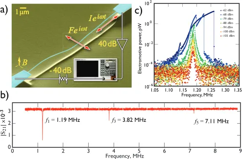
The aluminium NEMS beams used in our experiments were formed lithographically on a silicon substrate and after fabrication were measured using a standard microwave magnetomotive technique as shown in figure1(a). The beam is driven by an oscillating current which provides the necessary lateral Lorentz force generated in the ambient magnetic field (typically 5 T). The details of manufacturing and measurement setup are described in the Methods section.
Initial characterisations of our beams were performed in vacuum at a temperature of 4.2 K. An example of the frequency response of a 50µm beam in vacuum is shown in figure1(b). Resonance peaks were detected at frequencies of 1.19 MHz, 3.82 MHz and 7.11 MHz corresponding to the first three odd harmonics of the transverse flexural oscillations. The measured resonance frequencies can be compared to the expected values for a doubly-clamped beam of rectangular cross-section given by26:
fn=
kn2
π√48 w l2
√ E
ρAl
√
1+γn
( l w
)2∆
l
l , (1)
wherewandlrepresent the width and the length of the beam, respectively. The coefficientsknandγnhave different values
depending on the eigenmode of the resonance:26k
1=4.7300,γ1=0.2949,k2=7.8532,γ2=0.1453, andkn>3=π(n+1/2),
γn>3=12(kn−2)/kn3. Despite a weak granularity of our aluminium films, we assume that the Young’s modulus and density
of the beams are close to the bulk values ofE=70 GPa andρAl=2700 kg m−3respectively. The ratio∆l/ldescribes the
tensile strain of the resonators, which is expected to be substantial at cryogenic temperatures owing to the mismatch in the thermal expansion coefficients of the silicon substrate and aluminium film. Simple calculation shows that the unstressed 50µm long NEMS beam, with an approximately square cross-section of 0.1µm×0.1µm, should have a fundamental resonance at 209 kHz. The analysis of measured first, third and fifth eigenmodes shows that the actual average width,w, of our beams is about 0.18µm and the value of the tensile strain,∆l/l≈4.3·10−4, is an order of magnitude lower than that measured for shorter aluminium resonators27,28. We note that, due to an extremely high aspect ratio (l/w&102), our resonators have a significant compression stress at room temperature, which is clearly observable as bending on the micrograph of our typical beam (see figure1(a)), arising from the forced match of the substrate and deposited lattices at the time of deposition. Such obvious compression stress is not seen in shorter samples in other experiments27,28.
The power dependence of the frequency response of the 50µm aluminium beam near the first harmonic is presented in figure1(c). At low excitations the beam exhibits a linear response and has a quality factor (Q-factor) on the order of 103.
SimilarQ-factors are observed for higher harmonics and other beams in vacuum at 4.2 K. At high excitations the nonlinearities stiffen the beam and the resonance peak position shifts to a higher frequency as expected for the Duffing oscillator29. In addition to Duffing-like non-linearity, above intermediate applied power (-88 dBm) a second resonance becomes apparent which we believe is the lower-level excitation of the second of the two near-degenerate flexural modes of the almost square cross-section beam.
Since our ultimate goal is to probe liquid helium, it is instructive to deduce the force-velocity characteristics of the beam from the frequency response as a function of power to confirm the velocity below which the beam response remains linear. We have used the definition of quality factorQ= f1/∆f =πf1mAlv2/Pmaxto deduce the forceFLand velocityvvalues, and
applied them even when the resonance curve became non-Lorentzian:
v≈ √
Pmax
πmAl∆f
; FL≈
√
πmAlPmax∆f. (2)
HeremAl=ρAlV is the mass of the beam,∆f is the width of the resonance and Pmax=FLvis the maximum observable
Beam response in liquid helium
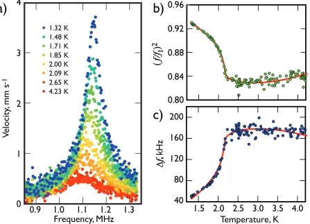
Figure2(a) presents the temperature dependence of the frequency response of the beam around the fundamental resonance. The resonance curves for all temperatures are very broad with widths of order 100 kHz,i.e. with quality factors of order 10. This guarantees that in-liquid measurements are completely dominated by liquid-induced dissipation since the corresponding intrinsic beam dissipation is negligible in comparison. The resonance frequency of the beam is also significantly lower (∼10%) than the vacuum value owing to the increase in effective mass of the beam arising from the induced flow of surrounding liquid helium. Helium flow can be thought of as having two components, the “pure potential” backflow of liquid needed to allow the passage of the beam, and the additional liquid that moves because it is viscously “clamped” to the beam.
The frequency sweeps in normal helium, between 4.2 K and 2.178 K, are almost indistinguishable and for clarity only representative data sets at 4.2 K and 2.6 K are plotted in the figure. As the temperature falls below the superfluid transition at 2.178 K, the damping experienced by the beam decreases and the resonance peak shifts towards higher frequencies (since below the transition decreasing masses of liquid are dragged along by the wire). The observed increase of the beam velocity with falling temperature reflects the decreasing damping with falling normal fluid fraction. At the lowest measured temperature of 1.3 K, where the helium has the highest superfluid fraction∼95%, the beam has the smallest observed resonance width with a corresponding maximum velocity of 3.6 mm s−1(which we note is much lower than the velocity for the onset of any intrinsic
nonlinear behaviour of the beam in vacuum).
For a quantitative description of the beam behaviour in liquid helium, we compare our results with the phenomenological two-fluid model for the superfluid. In the linear regime, at low beam velocities, we can treat our “beam + liquid” system as an externally-driven damped harmonic oscillator with a variable effective mass ˜mand a constant effective elastic constantk30. The ratio of resonance frequencies of the “bare” oscillator in vacuum, f1=
√ k/4π2m
Al, and our “beam + liquid” system,
f =√k/4π2m, can be written as:˜
( f1
f )2
= m˜ mAl
=1+β ρ
ρAl
+Bρnf
ρAl
S V
√
η πρnff
. (3)
The effective mass ˜mof NEMS beam with volumeV and surface areaSimmersed in a fluid with densityρand viscosityη consists of a self mass of the resonatormAland two additional contributions associated with: (i) a mass of fluid proportional
to the volume of the oscillating bodymρ ∝ρV; (ii) a mass of fluid in a layer of thickness the viscous penetration depthδ= √
η/(πρnff)dragged along by the oscillating motionmη∝ρnfSδ. CoefficientsBandβ are geometry-dependent parameters.
The theoretical predicted values in the case of an infinitely long rectangular cross-section beam with heighth and widthw moving perpendicular to the width areβ = (π/4)h/wandB=131.
The damping experienced by our system includes any intrinsic damping such as inter-crystalline friction within the material of the resonator itself, and external forces such as Stokes’ drag which describes the interactions with the surrounding fluid. At a temperature of 4.2 K this latter contribution dominates even for a beam oscillating in a rarefied helium gas at pressures as low as∼10 Pa. The Stokes’ drag force is proportional to the velocity of the oscillating body. The exact calculation of the proportionality coefficient requires the full solution of the flow field around the oscillating body and in the high-frequency limit is given byCS√πρnfηf, whereCis a geometrical constant independent of the fluid. For an infinitely long cylinder oscillating
perpendicular to its axis, the value of this constant is30C=2. For our 50µm beam with a resonance frequency of 1.2 MHz the viscous penetration depth is 80 nm at 4.2 K (150 nm at 1.5 K) and is comparable to the beam thickness, which means that the high-frequency approximation used here is marginal. That said, treating the cross-over from high-frequency to steady-flow behaviour even for a cylinder is a formidable (non-trivial) task even in classical hydrodynamics and a full treatment would not significantly benefit the description and core understanding of our main results31. The distance of the beam to the substrate at 2µm is far enough away not to influence the dynamics in our temperature range. Based on these assumptions, the resonance width for an oscillator immersed in a fluid can be expressed as30:
∆f =C S 2VρAl
√
ηρnff
π
( f f1
)2
. (4)
Figure2(b) shows as a function of temperature the measured change in the resonance frequency, presented as the square of the ratio of the resonance frequency in vacuum, f1to that measured in the liquid, f (as expressed in equation (3)). The rapid
increase in the frequency f below the superfluid transition temperature arises almost entirely from the reduction in the liquid viscously “clamped” to the beam as a consequence of the falling normal fluid fraction. The red solid line is the least-square fit of equation (3) using the parameters for liquid4He tabulated by Donnelly and Barenghi32. The measured data are in excellent agreement with the model over the whole temperature range. Similar results have been observed for our beams with shorter lengths and higher resonant frequencies.
Barenghi32. We found the following values for the geometric parameters:β =1.00±0.04,B=0.90±0.01 andC=1.99± 0.03.
The calculated curve fits the measured data excellently, except that there is a slight discrepancy between the data and the Stokes’ drag model at the lowest temperatures. It is clear that the intrinsic damping of this beam plays no role in the observed frequency width as it was nearlyan order of magnitude smallerin vacuum measurements. Several effects might contribute to this difference: (i) we could be generating quantum vorticity or exciting Kelvin waves on existing vortices attached to the beam; (ii) it is possible that we start to observe the onset of transition from the hydrodynamic to ballistic regime in the liquid phase; (iii) finally, we may be seeing the effect of acoustic emission.
Regarding the effect of turbulence, we would expect the nucleation of quantum turbulence to be triggered only at velocities an order of magnitude higher33. However, this has not hitherto been studied with such small objects and high frequencies. As to the possibility that we are seeing transition to the ballistic regime, unfortunately temperatures below 0.8 K needed to observe theT4dependence expected for the phonon damping in the ballistic regime, are not accessible with the current experimental apparatus. It is also unlikely that acoustic damping is solely responsible for the discrepancy observed since some high frequency beams exhibit lower measured damping. However, a standing acoustic resonance for a particular beam and cell cannot be ruled out as the reason for the higher-than-expected dissipation at a certain temperature. Since various NEMS samples have slightly different discrepancies, it is clear that systematic measurements of several beams of various length, and consequently frequencies, down to much lower temperatures are needed to determine the actual nature of these discrepancies.
Discussion
It is instructive to compare the temperature dependence of the resonance frequency of our NEMS with other devices which have been successfully used to probe the properties of superfluid helium. Using the two-fluid model we can make a reason-able prediction of which beam-like devices with a characteristic size of cross-section d2, density ρ
beam and the resonance
frequency f will have the highest frequency sensitivity to the temperature-dependent changes in superfluid. First, we can rewrite equation (3) as:
( f1
f )2
−1= 1
ρbeam
(
βρ+B4 d
√
ηρnf
πf )
. (5)
Then, setting the geometrical coefficientsB andβ to be on the order of unity for all resonators, and taking the right hand side (RHS) terms one by one, it is immediately clear from the leading coefficient that beams with lower material densities would be expected to be more sensitive. Quartz tuning forks (ρQ=2690 kg m−3) and aluminium beams (ρAl=2700 kg m−3)
are clearly favoured over denser NbTi wires (ρNbTi=6500 kg m−3). The first term on the RHS corresponds to the backflow
around the resonator, has only weak temperature dependence and can be neglected in the discussion. The second term, describing viscous clamping, predicts that an object with the smallest cross-section and the lowest frequency will yield the highest frequency sensitivity. Putting this all together we find that of the devices we have tested, the most sensitive should be the smallest diameter vibrating wire resonator manufactured from NbTi (d=0.9µm, f ≈103) closely followed by the aluminium 50µm long beam (d=0.18µm, f ≈106). Despite being manufactured from a denser material, the vibrating wire resonator should show a sensitivity approximately two times better than our 50µm long beam owing to its submicron size and very low frequency. Finally the thinnest available tuning fork (d=25µm, f ≈104) comes in at a sensitivity≈2.5 times worse than our 50µm aluminium beam.
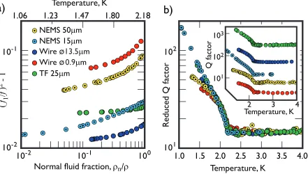
Figure3(a) shows the fractional frequency change for these NEMS, as a function of the normal fluid fractionρn/ρ from
the superfluid transition down to 1.1 K. It is clear that our 50µm and 15µm NEMS show a significant fractional frequency change over the whole temperature range, and are comparable to the smallest vibrating wire resonator and much more sensitive than a tuning fork. It is also worth noting that our NEMS do not show a significant saturation down to the lowest measured temperatures.
While a good frequency sensitivity is important for identifying the best resonator, a highQ-factor is also essential for a high signal-to-noise required for measurements. Using similar two-fluid-model arguments to those used above we can deduce from equation (4) that theQ-factor can be written as:
Q=2C∗ √
π ηρnf
( f1
f )2√
f dρbeam, (6)
where we can see that the thickest, densest and highest frequency beams will have the best quality factors. This of course is a necessary trade off since these factors tend to reduce the frequency sensitivity.
our conclusions, with the NEMS devices showing much betterQ-factors than the NbTi 0.9µm diameter wire, owing to their higher resonance frequencies.
Interestingly, the equation also suggests that the temperature dependence of the reducedQ-factor,Q/(√f1dρbeam), should
be almost identical for all resonators, provided the in-liquid and vacuum resonance frequencies are similar, which is the case to within 10% for all the data presented here. We have used theC∗coefficient as a scaling parameter to normalise all of the available data and reproduce the reduced quality factor in figure3(b). Despite the very different geometries of the resonators studied, the value ofC∗only varies by a factor of 4 (from 0.35 to 1.4), for all the resonators. In the figure it is clear that the reducedQ-factors of the 15µm beam with resonance frequency of 8 MHz and 25µm tuning fork below∼1.6 K increases more rapidly with decreasing temperature than those of the others. This would indicate that acoustic emission, which should increase very rapidly with the resonant frequency22, may not become the dominant damping for NEMS even at these low temperatures. Overall our results demonstrate that the use of NEMS beams as local superfluid temperature probes has a very exciting prospect since tuning forks and vibrating wires already work extremely well at low temperatures.
The absence of any saturation of theQ-factor of the high frequency beam down to 1.2 K warrants extending measurements down to dilution fridge temperatures. The device should enter the ballistic regime below 0.8 K with theQ-factor showing aT4temperature dependence, which would then reveal whether other mechanisms such as intrinsic damping in the beam
or acoustic emission become significant. Furthermore, low temperatures and correspondingly lower damping should allow us to investigate the nucleation of quantum turbulence as inferred from the force-velocity dependence of ”beam + quantum fluid” system. Possibly single-vortex sensitivity may eventually become achievable using NEMS owing to the well-defined geometry, high sensitivity and small size.
Armed with the knowledge that we can run these devices in superfluid 4He, we can now presume that they will also run in superfluid3He. We know3He is the best medium to cool electronic devices to the lowest temperatures12. Here the liquid temperatures can be taken routinely to temperatures below 100µK. This would have the immediate advantages that, first, the intrinsicQ-factor (inverse damping) of vibrating wire resonators immersed in superfluid3He usually exceeds the Q-factor measured in vacuum at low resonator velocities (because the liquid3He cools the material of the resonator to lower temperatures than can usually be achieved by cooling through the leads in a vacuum). Secondly, the small dimensions of the beam should make it an extremely sensitive detector of ambient quasiparticles and could lead to high resolution visualization of quantum turbulence or other topological defects present in3He-B. Thirdly, the coherence length of superfluid3He-B at zero pressure is 80 nm and is of the same order as the beam dimensions, thus opening another regime to probe superfluid3He-B.
However, the wider advantage would be that at these temperatures, as pointed out in the introduction, we are at the point when the low frequency nanobeams are on the brink of reaching their quantum ground state, especially if we choose a beam with somewhat higher frequency, say∼10 MHz. The challenge of performing such experiments in3He is that they
would require both small magnetic fields and minute power dissipation. To achieve the ultimate intrinsicQ-factors for the resonators, the highest sensitivity to the liquid and the necessary low dissipation would require that the aluminium is in the superconducting state. This requires an ambient field below 10 mT, which makes the excitation and detection of the beam motion rather demanding (bearing in mind that the results reported here were made in a 5 T field). However, this is within the capabilities of a SQUID-based voltmeter34. Additionally, recently developed superconducting diamond beams with a critical field of several Tesla35could be employed, or measurements utilising a microwave reflection technique that drive and detect beam motion electrostatically28could be adapted. We would also have to take precautions to reduce the ambient noise, but we are confident that this is possible in the ultra-quiet environments of our microkelvin cryostats36.
Methods
Fabrication and Experimental Setup
The NEMS resonators used in our experiments are formed on a silicon substrate by standard nanofabrication methods: electron-beam lithography, metal deposition and reactive ion etching. Our manufacturing technique allows the creation of doubly-clamped aluminium resonators over a broad range of lengths (l) from 0.5µm up to 500µm. All beams have a lithographically-defined width (w) and thickness (h) with dimensions of≈0.1µm and are clamped at both ends to a wider film of the same thickness. The beam is suspended above the substrate by 2µm. A scanning-electron microscope image of a typical aluminium NEMS beam is shown in figure1(a) together with the principle measurement schematics.
The NEMS are mounted on a chip within a small container inside the cryogenic system and connected by two coaxial cables to a network analyser. This setup allows the measurement of the transmission through the beam, which is characterised by a magnetomotive measurement scheme37. The 5 T magnetic fieldB necessary for the measurements is provided by a superconducting solenoid surrounding the sample. The beam orientation is such that the Lorentz forceFL∼IBl, a result of
All measurements on the beams were conducted in a4He evaporation cryostat operating over the temperature range from
4.2 K down to a base temperature of∼1.2 K. After the initial characterization of a beam in vacuum at 4.2 K, the cell was slowly filled with helium gas while the beam resonance was monitored and followed. At pressures greater than the saturated vapour pressure at 4.2 K,4He condenses and the cell fills with a liquid. We used the damping of a vibrating wire resonator located above the beam to monitor the helium level and to confirm that the beam was indeed fully submerged. The temperature of the cryostat was monitored and controlled both by a calibrated RuO2resistor and from a measurement of the4He saturated vapour
pressure32. The4He saturated vapour pressure was measured at room temperature just outside the cryostat on the pumping line. Both temperature measurement methods agreed to within 20 mK.
Data and software availability
All data used in this paper are available at http://dx.doi.org/10.17635/lancaster/researchdata/120, including descriptions of the data sets.
Acknowledgements
We thank S. M. Holt, A. Stokes, and M. G. Ward for excellent technical support. This research was supported by the UK EPSRC Grants No. EP/L000016/1, No. EP/I028285/1 and No. EP/K01675X/1. Yu. A. P also acknowledges support from the the Royal Society Grant No. WM110105. J. R. P. acknowledges support of the People Programme (Marie Curie Actions) of the European FP7 Programme under REA grant agreement 618450.
Contributions
R.G., S.K., M.S. and Yu.A.P. designed, fabricated and packaged the beams. D.I.B., A.M.G., S.K., M.T.N., Yu.A.P., J.R.P., M.P., M.S., R.S., V.T. and D.E.Z. developed custom measurement instrumentation and methods. S.K., M.P., M.S. and T.W. performed measurements. R.P.H., S.K., Yu.A.P., G.R.P, M.S. and V.T. performed calculations and analysis. S.K. and V.T. drafted the manuscript. All authors discussed the results and implications, and commented on the manuscript at all stages.
References
1. Burg, T. P.et al.Weighing of biomolecules, single cells and single nanoparticles in fluid. Nature446(2007).
2. Chaste, J.et al.A nanomechanical mass sensor with yoctogram resolution. Nat. Nano.7(2012).
3. Wilson, N. R. & Macpherson, J. V. Carbon nanotube tips for atomic force microscopy.Nat. Nano.4(2009).
4. Kara, V.et al.Nanofluidics of single-crystal diamond nanomechanical resonators.Nano Lett.15, 8070 (2015).
5. O’Connell, A. D.et al. Quantum ground state and single-phonon control of a mechanical resonator.Nature464(2010).
6. Wollman, E. E.et al. Quantum squeezing of motion in a mechanical resonator.Science349(2015).
7. Kraus, A., Erbe, A. & Blick, R. H. Nanomechanical vibrating wire resonator for phonon spectroscopy in liquid helium. Nanotechnology11, 165 (2000).
8. Defoort, M.et al.Probing Bogoliubov quasiparticles in superfluid3He with a ’vibrating-wire like’ MEMS device.J. Low Temp. Phys.183, 284 (2016).
9. Defoort, M.et al. Slippage and boundary layer probed in an almost ideal gas by a nanomechanical oscillator. Phys. Rev. Lett.113, 136101 (2014).
10. Gonz´alez, M., Zheng, P., Garcell, E., Lee, Y. & Chan, H. B. Comb-drive micro-electro-mechanical systems oscillators for low temperature experiments.Rev. of Sci. Instr.84, 025003 (2013).
11. Harris, G. I.et al.Laser cooling and control of excitations in superfluid helium. Nat. Phys.12, 788 (2016).
12. Bradley, D. I.et al. Nanoelectronic primary thermometry below 4 mk.Nat. Commun.7(2016).
13. Pickett, G. R., Enrico, M. P., Fisher, S. N., Gu´enault, A. M. & Torizuka, K. Superfluid3He at very low temperatures: a very unusual excitation gas. Phys B: Cond. Matt.197, 390 (1994).
14. Black, M. A., Hall, H. E. & Thompson, K. The viscosity of liquid helium 3. Journal of Physics C: Solid State Physics4 (1971).
15. Stalp, S. R., Skrbek, L. & Donnelly, R. J. Decay of grid turbulence in a finite channel. Phys. Rev. Lett.82, 4831 (1999).
17. Bradley, D. I.et al. Direct measurement of the energy dissipated by quantum turbulence.Nat. Phys.7, 473 (2011).
18. Bradley, D. I.et al. Breaking the superfluid speed limit in a fermionic condensate. Nat. Phys.(2016).
19. Gu´enault, A. M., Keith, V., Kennedy, C. J., Mussett, S. G. & Pickett, G. The mechanical behavior of a vibrating wire in superfluid3He-B in the ballistic limit.J. Low Temp. Phys.62, 511 (1986).
20. Goto, R.et al.Turbulence in boundary flow of superfluid4He triggered by free vortex rings.Phys. Rev. Lett.100, 045301 (2008).
21. Gu´enault, A. M. & Pickett, G. R. Liquid3He at ultralow temperatures: the long mean free path limit.Physica (Amsterdam) 126B(1984).
22. Bradley, D. I.et al. Crossover from hydrodynamic to acoustic drag on quartz tuning forks in normal and superfluid4He. Phys. Rev. B85, 014501 (2012).
23. Ahlstrom, S.et al. Frequency–dependent drag from quantum turbulence produced by quartz tuning forks in superfluid
4He. Phys. Rev. B89, 014515 (2014).
24. Pickett, G. Superfluid3He as a possible medium for detecting dark matter. In Gonzalez-Mestres, L. & Perret-Gallix,
D. (eds.)Proceedings of the Second European Workshop on Low Temperature Devices for the Detection of Low Energy Neutrinos and Dark Matter, 377 (Editions Frontieres, Gif-sur-Yvette, 1988).
25. Bradley, D. I.et al. Potential dark matter detector? The detection of low energy neutrons by superfluid3He. Phys. Rev. Lett.75, 1887 (1995).
26. Bao, M.Analysis and Design Principles of MEMS Devices(Elsevier Science, 2005).
27. Li, T. F.et al.High-frequency metallic nanomechanical resonators. Appl. Phys. Lett.92(2008).
28. Sulkko, J.et al.Strong gate coupling of high–Q nanomechanical resonators. Nano Lett.10, 4884 (2010).
29. Tajaddodianfar, F., Yazdi, M. R. H. & Pishkenari, H. N. Nonlinear dynamics of MEMS/NEMS resonators: analytical solution by the homotopy analysis method. Microsys. Techn.1 (2016).
30. Blaauwgeers, R.et al.Quartz tuning fork: Thermometer, pressure- and viscometer for helium liquids.J. Low Temp. Phys. 146, 537 (2007).
31. Landau, L. D. & Lifshitz, E. M. Fluid Mechanics, Second Edition: Vol. 6 (Course of Theoretical Physics) (Butterworth-Heinemann, 1987), 2 edn.
32. Donnelly, R. J. & Barenghi, C. F. The observed properties of liquid helium at the saturated vapour pressure. J. Phys. Chem. Ref. Data27, 1217 (1998).
33. Vinen, W. F. & Skrbek, L. Quantum turbulence generated by oscillating structures.Proceedings of the National Academy of Sciences111, 4699 (2014).
34. Bradley, D. I. & Hayes, W. M. An RF-SQUID amplifier system for use with vibrating wire resonators.J. Low Temp. Phys. 119, 703 (2000).
35. Bautze, T.et al.Superconducting nano-mechanical diamond resonators.Carbon72, 100 (2014).
36. Cousins, D. J.et al.An advanced dilution refrigerator designed for the new Lancaster Microkelvin facility. J. Low Temp. Phys.114, 547 (1999).
37. Ekinci, K. L., Yang, Y. T., Huang, X. M. H. & Roukes, M. L. Balanced electronic detection of displacement in nanoelec-tromechanical systems. Appl. Phys. Lett.81(2002).
38. Le Mi´ere, J.-C. An Investigation of Quantum Turbulence Using a 1µm Diameter Wire Resonator. Master’s thesis, Lancaster University (2013).
39. Noble, M. T. Behavior of Oscillatory Wires in Liquid4He at 4.2 K and 1.5 K. Master’s thesis, Lancaster University
(2015).
0
1
2
3
4
5
6
7
8
9
Frequency, MHz
0
1
2
3
|
S
21|
X
10
-3
f
1=
1.19 MHz
f
3=
3.82 MHz
f
5=
7.11 MHz
b)
Fe
i
ω
t
I e
i
i
ω
ω
ω
t
t
t
- 40 dB
40 dB
1
µ
m
B
a)
c)
-62 dBm-68 dBm -79 dBm -88 dBm -94 dBm -100 dBm -105 dBm
Frequency, MHz 1.30
1.10 1.25
1.05 1.15 1.20 1.35
10 0
10- 2
10 2
10- 6
El
ectr
o
mo
ti
ve
po
w
er
, pW
[image:8.612.61.555.140.465.2]10- 4
Figure 1.The behaviour of the aluminium beams in vacuum.(a)A micrograph of a typical doubly-clamped aluminium beam as used in experiments. Despite an obvious compression of the resonator at room temperature, our beams have a tensile stress at cryogenic temperatures due to the significant differential thermal contraction of the silicon substrate and the
deposited aluminium film. The resonator shown here has a nominal length of 15µm with a cross-sectional dimensions of 0.1µm×0.1µm, with an expected resonance frequency at cryogenic temperatures of 8.5 MHz. The beam is placed in a perpendicular magnetic field and connected in the microwave circuit, shown schematically in the figure. Transmission measurements are performed with a network analyser. The microwave drive from the network analyser is attenuated by -40 dB with an attenuator located at 4.2 K; the microwave signal transmitted through the sample is amplified by a 40 dB
amplifier at room-temperature.(b)A typical microwave transmission measurements of our 50µm beam in vacuum at 4.2 K in a 5 T magnetic field. A wide frequency sweep at -90 dBm of applied power clearly shows the first three odd harmonics of the beam. The quality factors of all three harmonics are approximately 103.(c)The frequency characteristics of
Frequency, MHz
0.9
1.0
1.1
1.2
1.3
3
2
1
4
0
V
el
o
ci
ty
, mm
s
-1
1.71 K
2.00 K 1.48 K
2.65 K 1.85 K
2.09 K 1.32 K
4.23 K
a)
c)
Temperature, K
3.5
3.0
2.5
2.0
1.5
4.0
120
80
40
160
200
∆
f
, kHz
b)
0.92
0.88
0.96
0.84
0.80
(
f/
f
1)
[image:9.612.61.508.165.488.2]2
Figure 2.The response of the beam in liquid4He.(a)The velocity resonance curves of the 50µm beam oscillating in liquid
4He. The output power of the network analyser was maintained at a constant -50 dBm with an additional -40 dB external
attenuation. The shape of the resonance is independent of temperature in the normal fluid above the transition temperature Tλ =2.178 K. The decrease in density of the normal component of the liquid belowTλ results in a decrease of the Stokes drag, leading to a significant increase in the NEMS quality factor along with an increase in the resonant frequency as less fluid is being dragged with the beam.(b, c)The temperature dependence of the resonance frequency and the resonance width of the 50µm nanomechanical resonator. Each data point of figures(b)and(c)was obtained from a complete resonance curve for the beam. The solid lines are the theoretical models given by equations (3) and (4) for the(b)and(c)respectively. We treated all three geometrical factors as fitting parameters and have found the following values:β=1.00±0.04,
3.5
3.0
2.5
2.0
1.5
1.0
4.0
10
110
2Red
uced
Q
fa
cto
r
Temperature, K
Temperature, K
2
3
4
10
210
110
3Q
fa
cto
r
Normal fluid fraction,
ρ
n/
ρ
10
-110
-210
010
-210
-1(
f
1/
f
)
2
- 1
Temperature, K
1.06
1.23
1.47
1.80
2.18
NEMS 15
µ
m
NEMS 50
µ
m
Wire
ø
13.5
µ
m
Wire
ø
0.9
µ
m
TF 25
µ
m
[image:10.612.64.505.214.464.2]a)
b)
Figure 3.A comparison of the frequency response of the NEMS oscillators with superconducting NbTi vibrating wires38,39 and quartz tuning-fork40operated in the superfluid.(a)The frequency shift as a function of temperature. The lightness and small geometrical sizes of the NEMS resonators give a higher sensitivity to the normal fluid component of the4He than the