Product Maintainability Design Method and Support
Tool Based on Feature Model
Yufeng DING
School of Mechanical and Electrical Engineering, Wuhan University of Technology, Wuhan, China. Email: [email protected]
Received June 5th, 2009; revised June 29th, 2009; accepted July 7th, 2009.
ABSTRACT
Maintainability is an important character which is given by product design process. The maintainability design criteria and measure index used in product maintainability analysis are summarized and discussed in this paper. A product maintainability design method is studied by integrating the product feature model, maintainability design criteria with measure index. Product feature model can be built on the basis of the product feature library quickly. Product feature library for steam turbine design is created by using SolidWorks design library origination structure. A methodology which supports the design and development of product maintainability design support tool (PMDSTs) is put forward. The function of PMDSTs is designed by using UML (Unified Modeling Language) use case diagram, it is developed by using VC++ 6.0. The maintainability analysis application case of steam turbine-generator system is given at last.
Keywords:Maintainability Design, Product Design Process, Steam Turbine, Solidworks
1. Introduction
If a product has poor maintainability, the maintenance activities which have to be performed on it during its life cycle are difficult, it will result in increasing the costs, and also more time is required to accomplish the main-tenance tasks. Designs for maintainability had played an important role in the complex product deign process. Maintainability is the probability that required mainte-nance will be successfully completed in a given time period. It is a design characteristic that affects accuracy, ease, and time requirements of maintenance actions. It may be measured by combining factors such as fre-quency of maintenance, maintenance costs, elapsed maintenance or repair times, and labor hours etc.
Design for maintainability requires a product that is serviceable and supportable—better yet if the design in-cludes a durability feature called reliability (absence of failures) then you can have the best of all worlds [1].
Maintainability is an important character which is given by product design, it makes easy to be repaired for the mechanical system. It has a specific effect on the maintenance cost of mechanical systems [2].
In order to realize product design for maintainability, some approaches and software tools have been studied and developed. A maintainability evaluation approach based on fuzzy logic is presented in [3], fuzzy linguistic variables are employed in order to represent and handle
the design data available early in the design process. The measure tool of the product maintainability is developed. Maintainability and safety indicators at design stage for mechanical products are studied in [4]. The assessment procedure uses product 3D (Dimension) CAD (Computer Aided Design) model and associated semantic matrix gathering information from the product components’ criticality and reliability.
2. Product Integration Maintenance Model
Product CAD model doesn’t include product mainte-nance feature information; it can not provide support for product maintenance. So it needs to build product inte-gration model by combining CAD model and mainte-nance feature information. Product integration model is composed of shape feature Fs, heat treatment feature Fh,
management feature Fm and maintenance feature Fma.
poli-cies and procedures, organizational interfaces, program tasks, evaluation and subcontractor/supplier activity etc. [5].
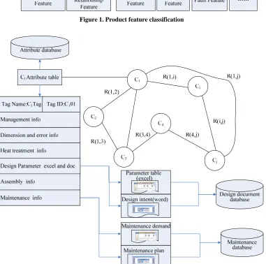
Product maintenance integration model is shown in Figure 2. Ci means ith component. It can be a part or a
sib-assembly. R(i,j) represents the assembly relation be-tween ith component and jth component. It is marked in the link arc between ith component and jth component.
Every component has an attribute table, all attribute ta-bles are saved in the attribute table. Every attribute table file saves all feature informations of component Ci. Some
[image:2.595.118.479.196.339.2]data files such as design parameter table (excel file), de-sign intent (word file), maintenance plan (Microsoft pro-ject file) are stored in design document data or mainte-nance data. They have a link in the Tag file. Tag file will look for the relevant file by the link [5].
[image:2.595.109.490.321.699.2]Figure 1. Product feature classification
. Design for Maintainability
aintainability
of design, can be
combination of the following
fac-re several approaches to evaluate the main-ta
include m
pair (MTTR)
very crucial and it
3
fined on the basis of a3.1 The Principles of Design for M
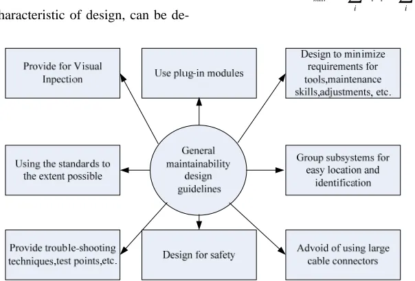
The design engineer is anxious to verify if product main-tenance tasks can be accomplished with the available maintenance logistics and evaluate the performance of these tasks in design stage. The designer must change his/her design solution if the maintenance tasks are dif-ficult, or even impossible to be accomplished in the given conditions. Some of the important general design guidelines that maintainability professionals have devel-oped are shown in Figure 3 [6].
Maintainability criteria are composed of intrinsic cri-teria and contextual cricri-teria [4]. Intrinsic cricri-teria includes repairability, ability to be repaired after failure or damage; accessibility, easiness to reach a component inside the assembly; assemblability, ability to be assembled from an assembly; disassemblability, ability to be removed from an assembly; standardization, standard component or equipment; interchangeability, ability to be replaced with another component; survivability, ability of the product to continue to work after the failure of a consid-ered component. Contextual criteria includes redundancy, for components existing in multiple equivalent occur-rences; Competencies, human required to diagnose and to repair; Toolings, maintenance equipments like keys, screwdrivers...; Logistics, delivery of spare parts, trans-portation of maintenance team...; Environment, working conditions like lighting, temperature...; Delectability, easiness to detect failure and components concerned with; Testability, ability for a component or a sub-system to be tested...; Maneuverability, ability for a component or sub-system to be handled; Auto diagnostic: ability for a system to perform self-testing procedures.
3.2 Maintainability Measure
Maintainability, as a characteristic
tors. They are Maintenance times, Maintenance fre-quency and Maintenance cost. The three factors are de-pendant on the fact that the system is operated and main-tained in accordance with prescribed procedures and re-sources. From a systematic perspective, maintenance includes corrective maintenance and preventive mainte-nance. And from a software perspective, maintenance includes adaptive maintenance and perfective mainte-nance.
There a
inability of a product at the design stage. They are maintainability design checklists, maintainability evalua-tion using physical mock-ups, maintainability evaluaevalua-tion using digital mock-ups and virtual reality and maintain-ability evaluation using quantitative approaches.
The measures used in maintainability analysis
ean time to repair, mean active preventive maintenance time, and mean active corrective maintenance time, maximum corrective maintenance time, and mean main-tenance downtime [7].
3.2.1 Mean Time to Re
Maintenance time to repair (MTTR) is
depends mainly on the product configurations. MTTR measures the elapsed time required to perform a given maintenance activity and is subsequently used to calcu-late system availability and downtime. Exponential, log-normal, and normal probability distributions can all rep-resent mean time to repair. The normal distribution is normally assumed for mechanical or electromechanical equipment with a remove-and-replace maintenance con-cept.
( ) /
m m
mttr i i i
i i
[image:3.595.150.452.501.706.2]T
T
(1).2.2 Mean Preventive Maintenance
inspections,
3 Time
Preventive maintenance activities such as
calibrations, and tuning keep equipment at a specified performance level. The objective of a preventive main-tenance program is to postpone the point at which the equipment or any of its components wears out or breaks down.
( )( )
k
m pi pti i
m p k pti i T F T F
(2)Tmp is the mean preventive time. Tmpi is the elapsed time
Corrective Maintenance Time
nting for preventive maintenance task i, for i= 1,2,3 . . . k.Fpti
is the frequency of preventive maintenance task i, for i =1, 2, 3 , . . . ,k. k is the number of preventive mainte-nance tasks.
3.2.3 Median
Mean corrective time is a composite value represe the arithmetic average of the individual maintenance cy-cle times. Maintainability is the ability of a product to be maintained. Calculation of the median corrective main-tenance time depends on the distribution describing time to repair. The median corrective maintenance time for lognormal distributed repair time is given by
2 / exp( )
Tmed Tmttr (3)
2
is the variance around the mean val log
ive Maintenance Time
tential ue of the natural arithm of repair time.
3.2.4 Maximum Correct
This measures the time required to complete all po repair activities up to a given percentage, often the 90th or 95th percentiles. The maximum corrective mainte-nance time for lognormal distributed is
antilog(
mcm m
T T k) (4)
Tmcm is the maximum corrective maintenance time. Tm is
the mean of the logarithms of the repair times. is the standard deviation of the logarithms of repair ti es. k is equal to 1.28 or 1.65 for the 90th and 95th percentiles.
3.2.5 Mean Maintenance Downtime
m
restore equipment
(5)
Tmmd is the mean maintenance down
ad ld
repair, beginning at time t = 0, will be aintainability function,
t is time.fr(t) is the probability density function of the
repair time.
ipment can be reached for service, important
of ility can lead to
. For example, a
a
Accessibility Value
This is the total time needed either to
to a specified performance level or to maintain it at that level of performance. Thus it includes active corrective and preventive maintenance times, administrative and logistic delay times.
mm
T d TmamTadTld
time. Tmam is the
mean active maintenance time, or mean time required to conduct corrective and preventive maintenance related tasks. T is the administrative delay time. T is the
lo-3.2.6 Maintenance Function
The maintainability functions are used to predict the probability that a
gistic delay time.
accomplished in a time t. The m m(t) for any distribution is expressed by
0
( )
t
t r
m
f t dt (6)3.2.7 Maintenance Accessibility Evaluation
Accessibility is the relative ease with which a part or piece of equ
ment, or repair. The lack of accessibility is an
maintainability problem and a frequent cause of ineffec-tive maintenance.
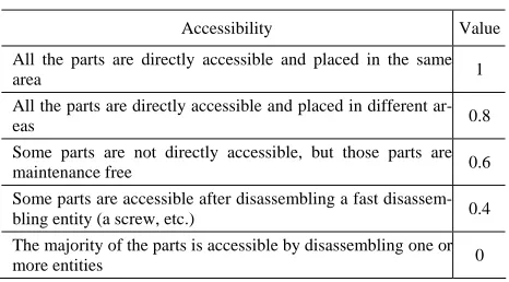
The evaluation may also be performed by assigning to each maintainability criterion, a numerical value between 0 and 1 using a table, like the one listed in Table 1 [3].
3.3 Maintainability Cost Analysis
Maintainability is an important factor in the total cost equipment. An increase in maintainab
reduction in operation and support costs
more maintainable product lowers maintenance time and operating costs. Furthermore, more efficient maintenance means a faster return to operation or service, decreasing downtime.
The data to be input into a life cycle cost model in-clude the purchase price of the product, mean time be-tween failures (MTBF), MTTR, average material cost of
[image:4.595.307.540.593.722.2]failure, labor cost per preventive maintenance action, labor cost per corrective maintenance action, installation costs, training costs, the warranty coverage period cost of carrying spares in inventory, and shipment forecasts over the course of the product's useful life [8].Corrective Maintenance cost estimation model estimates the correc-tive maintenance labor cost for a piece of equipment. The annual cost is expressed by
Table 1. Accessibility evaluation
All the parts a e same
area 1
re directly accessible and placed in th
All the parts are directly accessible and placed in different
ar-eas 0.8
Some parts are not directly accessible, but those parts are
maintenance free 0.6
Some parts are accessible after disassembling a fast disassem-bling entity (a screw, etc.) 0.4 The majority of the parts is accessible by disassembling one or
L mttr
(SOH)(C )(T )
CM
C
mtbf
T
SOH represen
)
ts the scheduled operating hours of the equipment. CL is the maintenance la
Tmtbf is the mean time between failures for the equipm
Tm
e under Implied in this
defi-The system reliability,
(7
bor cost per hour. ent.
ttr is the mean time to repair for the equipment. 3.4 System Reliability Analysis
Reliability can be defined as the probability that a system will perform properly for a specified period of tim a given set of operating conditions.
nition is a clear-cut criterion for failure.
Let Ri be the reliability of subsystem i and rij be the
re-liability of component, in subsystem j,
1 j nii=1,2, …,k. Then
1
( ) ni ( )
i j ij
R t
r t (8)say R(t), is given by
1 1
( ) 1 k 1 ni ( )
i i j i
R t
r tjted in par-allel, with subsystem i consisting of ni
series for i=1,2,y,k. Such a system i ries–parallel sy
(9)
The system consists of k subsystems connec
components in s called a se-stem [9]. Figure 4 shows the diagram of a series–parallel system [10].
The system mean time to failure (MTTF) can be derived in the following form:
1
( ) 1 1 ... i
mttf l
l i k n
(10)
1
1 k ( 1)l
T
4. The Development and Application of
Product Maintainability Desi
Software
A
i-na Many features can be created once and
gn Support
4.1 Product Feature Library
library feature is a frequently used feature, or comb tion of features.
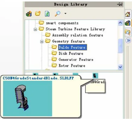
[image:5.595.312.534.506.706.2]then save in a library for future use. Product feature is organized according to product feature classification of Figure 1.The product feature can be built and saved in
Figure 4. Series–parallel system
design library of Solidworks. The directory structure can be built in the directory of install_directory\data\design library. To create a library feature that includes references, it is needed to dimension the library feature relative to the base part on which designer create it. Ref-erences create dimensions used to position the library feature (*.sldlfp) on the model (*.sldprt). Steam turbine feature library in the SolidWorks is shown in Figure 5.
4.2 Product n Feature
e
into they are front axis feature(AFA), front seal Feature Modelling Based o
Library
Industry steam turbine is composed of about tens of thousands of parts. The rotor, blade and cylinder of steam turbine work under the condition of high temperature and impulsion. They have high manufacture precision. The rotor of steam turbine is the most important, highest pre-cision and most complicated part in the steam turbin product. Rotor includes thousands of dimensions.
For example, steam turbine rotor axis can be divided five parts,
feature(AFGS), whole blade wheel feature(ABW), back seal
feature(ABGS) and back axis feature(ABA) .It can be
rep-resented in equation (11).
FA FGA
Fr A A ACAABGAABA (11)
All features of steam turbine rotor can be organized in the design feature library in the SolidWorks. But the first st
le which is integrated with the geometry feature. Steam turbine feature libr
SolidWorks is shown in Figure 5.
ep must be done is to classify the features according to component classification and recognize the feature di-mension. Some dimension relation can be built in some equation. The maintenance feature information had been organized into attribute tab
ary in the
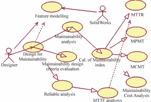
[image:5.595.63.279.618.711.2]Figure 6. The use case diagram of p oduct maintainability design support tool
4.3 The Development Process of PMDSTs
PMDSTs is a typical customization software. It can not be run without 3D CAD software SolidWorks platform. The development process of product maintainability de-sign support software obeys following methodology.
1) Design the function of product maintainability, de-sign support tool by using use case diagram.
2) Build main framework DLL (dynamic link library) using SolidWorks COM Add-In Wizard.
3) Build every function module DLL in C++ language. 4) Call every function module DLL in main DLL framework by using LoadLibrary method.
5) Test software function and performance by using SolidWorks Add-in interface.
The use case diagr
ign support tool is shown in Figure 6.The PMDSTs in-ity and
odel is
by us
maintainability de
co
re is a kind of C
d in the server computer. W
The function StartApplication and TerminateApplica-tion which is used to connect the solidWorks and termi-nate the PMDST are as follows.
bool CSteamTurbineSysApp::StartApplication(void) { // add menus to the active document
AddMenus(); //Add toolbars AddToolbars();
// create a control item to handle application-level events
swAppEvents* eventApp = new swAppEvents; eventApp->OnCreate(m_pSldWorks);
return TRUE; }
{ if (m_pSldWorks == NULL)
veToolbars();
if (m_pActiveDoc != NULL) m_pActiveDoc->Release(); r
am of product maintainability de- SysApp::TerminateApplication(void) void CSteamTurbine-s
clude feature modeling, design for maintainabil reliable analysis use case etc. Product feature m built in the 3D CAD software Solidworks. Design for maintainability and reliable analysis is carried out based on the product feature modeling. The part feature infor-mation and assemble feature relation can be extracted
ing Solidworks API (Application Program Interface) function.
The system is developed by using Visual C++ 6.0 and Microsoft SQL Server 2000. Product
sign criteria are stored in the Database. The database is nnected using ODBC (Open database Connectivity). The maintainability design support softwa
/S (Client/Server) software. Windows 2000 Server OS (Operation system) is installe
indows XP OS is installed in Client computer. The main framework DLL is created into a visual C++ DLL or visual C++ .NET DLL add-in using the SolidWorks COM Add-In Wizard included in the SolidWorks API SDK (Software Development Kit) [11].
return;
// remove all menus RemoveMenus(); //remove the toolbars Remo
// release the PropertyManager object ReleasePage();
LPMODELDOC pModDoc = NULL; HRESULT res =
TheApplica-tion->GetSWApp()->get_IActiveDoc(&pModDoc); if( pModDoc == NULL )
TheApplication->m_pActiveDoc = NULL; int count = m_EventList.GetCount(); for (int i=0; i<count; i++)
{ CObject* headEvent =
m_EventList.GetHead();
in main DLL
fr ::LoadLibrary method is as follows.
tyAnalysis ()
nalysis interface function
AppPath=GetAppPath();
CADServer";
_pSldWorks= TheApplication->GetSWApp(); odDoc = NULL;
m &pModDoc);
OC pPartDoc = NULL;
D D_IPartDoc,(LPVOID
*)
I *
SeriousDe-gr SLDWORKS)
;
:\\Steamturbine
Main-s.dll ca
oc ProcAddress(hmod,"
);
ULL) ,m_pSldWorks);
4. Index Analysis Case
Th rocess block diagram of a steam turbine-generator
.
M rator
sy
// disconnect from SolidWorks m_pSldWorks->Release(); m_pSldWorks = NULL; }
Every function module DLL is called amework by using
void Maintainabili {// MaintainabilityA CString m_AppPath; m_
CString strConnect;
LPSLDWORKS m_pSldWorks; // strConnect="MT
m
LPMODELDOC2 pM HRESULT res =
_pSldWorks->get_IActiveDoc2( LPPARTD
res = pMod-oc->QueryInterface(II
&pPartDoc);
typedef void (WINAP
ee)(LPMODELDOC2,LPPARTDOC,LP
HINSTANCE hmod; hmod = ::LoadLibrary(_T("D
tenanceSoft\\ MaintainabilityAnalysis.dll")); if(hmod==NULL)
{AfxMessageBox(_T("MaintainabilityAnalysi n not be found in current directory!")); }
SeriousDegree lpproc;
lppr = (SeriousDegree)Get
MaintainabilityAnalysis "
if(lpproc!=( MaintainabilityAnalysis)N (*lpproc)(pModDoc,pPartDoc FreeLibrary(hmod);
}
4 Maintainability Measure
e p
system is shown in Figure 7 [12]. In the design process of steam turbine-generator system, MTTR and MTBF etc
aintainability measure index of steam turbine-gene stem is calculated as follows.
39
( ) /
m m
i
T
T
227 105.9370.43 i
mttr i i i
6 10
9 2.69 mtbf
T
96.2
mtbf T A
T T
mtbf mttr
easure
inde is shown in
Fig-ure 8. Every Sub-system/assembly MTBF value must be The calculation process of maintainability m
[image:7.595.308.544.85.210.2]x of steam turbine-generator system
[image:7.595.309.537.256.441.2]Figure 7. Process block diagram of a steam turbine-gen- erator system
Figure 8. The calculation of maintainability measure index
ca
5. Conclusions
In this paper, the maintainability design criteria and measure index used in product maintainability analysis are discussed. A product feature library for steam turbine design is built. The feature library can support steam turbine product feature modeling quickly. Product main-tainability design method based on feature modeling can help to analyze product maintainability in the product design process. PMDSTs is developed by using Visual
tainability design criteria and maintain-bility measure index in the design stage. This method will help to enhance product maintainability efficiently. PMDSTs will be used to product computer support col-laborative design (CSCD) process through the next step
lculated at first in order to get MTTR, MTBF and availability etc. index of steam turbine-generator system. The designer can read Solidworks 3D feature model of current subsystem by pressing ‘View 3D Model’ button.
C++ 6.0 and Microsoft SQL Server 2000. PMDSTs can support designer to evaluate product maintainability by applying main
of developing new collaborative support function.
6. Acknowledgment
This paper is supported by the Key Technologies R&D Program of Wuhan City (No. 200810321153)and Wuhan Youth Science and Technology Chenguang Pro (No.200750731289).
REFERENCES
[1] http://www.barringer1.com/jul01prb.htm.
[2] B. Abdullah, M. S. Yusoff, and Z. M. Ripin, “Integration of design for modularity and design for assembly hance product maintainability,” Proceddings of 1st Inter-national Conference 7th AUN/SEED-Net Fieldwise seminar on Manufacturing and Material processing, pp. 263–269, University Malaya, 2006.
proach for maintainability evaluation in the design
proc-nt (IEEM) 2009.
[6] M. Pecht, “Pr ainability, support-ability handbo Raton, Florida, pp.
gram 191–192, 1995.
[7]
to en- [9] W. Kue, V. R. Parsad, F. A. Tillman and C. Hwang, “Op-timal reliability design: Fundamentals and applications,” Cambridge University Press, 2001.
[10] A. M. Sarhan, “Reliability equivalence factors of a
gen-[3] C. A. Slavila, C. Decreuse, and M. Ferney, “Fuzzy
ap-ess,” Concurrent Engineering, Vol. 13, No. 4, pp. 291–300, 2005.
[4] A. Coulibaly, R. Houssin and B. Mutel, “Maintainability and safety indicators at design stage for mechanical products,” Computers in Industry, Vol. 59, No. 5, pp
[12
438–449, 2008.
[5] Y. F. Ding and B.Y. Sheng, “Study on product mainte-nance integration model,” Submit to The IEEE Interna-tional Conference on Industrial Engineering and Engi-neering Manageme
oduct reliability, maint ok,” CRC Press, Boca
B. S. Dhillon, “Engineering maintainability,” Eelservier, 2008.
[8] H. Reiche, “Life cycle cost in reliability and maintain-ability of electronic systems,” Computer Science Press, Potomac, Maryland, pp. 3–23.1980,
eral series–parallel system,” Reliability Engineering and System Safety, Vol. 94, No. 2, pp.229–236, 2009.
[11] SolidWorks Corporation. “Solidworks 2000 API help,” 2006.