REVISIONS
uvl
DESCRIPTIONA
I
ENGINEERING RELEASE PER ERO.10781PRODUCT SPECIFICATIONS
MINI
DOUBLE SIDED RECORDING
FLEXIBLE DISK DRIVE
MODEL TMlOO-4
96 TPI DSR
SIGNATURES DATE
I
DAnI
DRICHK INPIl
I
I
I
I
THC 1 .. ,.OIt.AT,ON CONTAINeo MC.CON I . TM, ~.oP.'tTy O. TANDON M.ONeTIC. NO
,.O"TION 0 ' TII4I. DATA S"ALL.' . . . D t - - - + - - - I ~~~CILp,°::~C::::
...
~~.D~:~~::~~".~:: DR.wtnfOUT . . . . CI'IC WltITTE'" ~I."I •• ION t - - - _ + _ - - I
lanaon
' . 0 " T"HDOH H".H."':. CHIC ~ UNLESS OTHERWISE SPECIFIED . /
TITLE
~~
.xx* :
It INCIt MODEL TM100-4t---_+_~
~
*
*
I/~ PRO,. INCIl MATTSON' 121879PRODUCT SPEC
-~
*
MINI-DOUBLE SIDED RECORDINGSHAAJt COItNDS f - - - + - - i F LEXI B LE DISK DR IV E
)c • • 010
~
~
~S~A~E
...
r
COOl_ 1DENT_ _ NO
.... OWG _ _ NQ_.
_1_79_0_1'P.1!!!1!!!!!~~I!IIII~""
1.0
1.1
1.2
1.3
1.4
REVISIONS
DESCRIPTION DATE DR CHK APPR
SEE PAGE 1
SCOPE
The Tandon Magnetics Corporation Flexible Disk Drive is a compact Data Storage device utilizing an Industry Standard 5.25 inch Diskette (133.4mm).
The Flexible Disk Drive provides double density capability when a Modified Frequency Modulated (MFM) or other appropriate Recording Technique is utilized. The encoding and decoding of the data is the user's responsibility.
WRITE PROTECT (STANDARD)
When a Write Protected Diskette is inserted in the Flexible Disk Drive, the Write Electronics are disabled.
BUSY INDICATOR (STANDARD)
A Busy Indicator located on the Front Panel will become illuminated when the Flexible Disk Drive is selected.
DAISY CHAIN CAPABILITY (STANDARD)
The unit provides Address Selection and gating Functions necessary to Daisy-chain a maximum of four (4) Drives at the user's option. The last unit on the Daisy Chain terminates the Interface. The terminations are accomplished by a resistor array plugged into a D.I.P. Socket.
INTERNAL TRIM ERASE (STANDARD)
The Flexible Disk Drive provides internally the necessary control signal for proper Trim erasure of Data.
TITLE
lanaan
MODEL TM100-4
PRODUCT SPEC
-MINI-DOUBLE SIDED RECORDING FLEXIBLE DISK DRIVE
SIZE ICOOlIOlNTNO. DWG NO. REV
A
179011 A20
2.1.1
2.1.2
2.1.3
2.1.4
2.1.5
2.1.6
PERFORMANCE CHARACTERISTICS
HEADS
REVISIONS
DESCRIPTION
SEE PAGE 1
DATE DR CHK APPR
Two (Double Sided Recording) T .M.C. Patented Design (one Fixed - one Gimbaled). Wear guaranteed 20,000 hours in media contact.
TRACKS:
80 per side 160 total
.264 mm (l0.4 milli inch) Spacing 34.39 mm Track Radius (inside) side 1
RECORDING:
231.37 FR/mm (5877BPI MFM) inside track, Head #1 125 K Bits/Sec (Single Density)
25 K Bits/Track (Uniformated Single Density) 4.00 Mega Bits/Diskette (Unformated Single Density)
MEDIA
133.4 mm (5.25 Inch) Industry Standard Diskette 3.6 x 10⁶ Passes per Track Minimum wear guarantee
DISK SPEED
300 R.P.M.
±
1.5% I.S.V.±
3%Latency lOOms Nominal 250 Milli-Sec Start Time MAX 150 Milli-Sec Stop Time MAX
ACCESS TIME
3.0 Millisec - Track to Track 15 Millisec - Heads Settle Time
TITLE
lanaon
MODEL TM100-4
PRODUCT SPEC -MINI-DOUBLE SIDED RECORDING
FLEXIBLE DISK DRIVE
SIZE
I
CODIIOENT NO. DWG NO. REVA
I
179011 A2.1.7
2.1.8
REVISIONS
DESCRIPTION DATE DR CHK APPR
ERROR RATES (MAXIMUM)
One Recoverable error in 109 Bits. One non-Recoverable Error in 1012 Bits. One seek error in 106 seeks.
SEE PAGE 1
These error rates are exclusive of external sources, i.e. user Electronics, Defective Diskette, Contaminated Diskette, etc.
ELECTRO-MAGNETIC CHARACTERISTICS
The TMC Flexible Disk ,Drive is designed to minimize electrical interference generated internally, and propagated through Space or on Associated Conductors.
,I" j
TITLE
lanaon
MODEL TM100-4
PRODUCT
SPEC-MINI-DOUBLE SIDED RECORDINGFLEXIBLE DISK DRIVE
SIZE ICOO£ IO£NT NO. OWG NO.
A
179011REV
A
3.0
3.1
3.1.1
3.1.2
3.1.3
3.1.4
REVISIONS
REV DESCRIPTION DATE DR CHK APPR
SEE PAGE 1
ENVIRONMENTAL SPECIFICATIONS
The Drive will meet its operational specifications under the following environmental conditions:
TEMPERATURE
16°C to 44°C (60°F to 112°F) Operating -40°C to 71°C (-40°F to 160°F) Non operating
RELATIVE HUMIDITY
20 - 80% Operating (Non condensing)
5 - 95% Non operating (Non condensing)
ALTITUDE
304.8 m (500 ft) below Sea Level to 15,240 m (50,000 ft) above Sea Level Operating or Non Operating.
SHIPMENT
When prepared for shipment by TMC, it will meet the requirements of NSTA Pre-Shipment Test Procedure Project 1 A.
TITLE
lanaon
MODEL TM100-4
PRODUCT SPEC
-MINI-DOUBLE SIDED RECORDINGFLEXIBLE DISK DRIVE
SIZETCODlIDlNTNO. DWG NO.
A
I
179011REV
A
4.0
f 4.l
4.2
4.2.l
REVISIONS
DESCRIPTION· DATE DR CHK APPR
SEE PAGE 1
MOUNTING
The Flexible Disk Drive may be mounted in any of the following planes: (Upright, Horizontal or Vertical). When mounted horizontally, recording Head #1 ( top) must be the upper most head. Mounting holes are provided in various locations for attachments to user supplied mounting Brackets. See Figure #1.
PHYSICAL DIMENSION AND WEIGHT
Figure #1 illustrates the Physical Dimensions of TMC Flexible Disk Drive. Summarized as follows:
Weight: 1.45 Kg (3.2 lb) Height: 85.85 mm (3.38 inches) Width: 149.1 mm (5.87 inches) Length: 203.2 mm (8.0 inches)
TITLE
lanaan
MODEL TM100-4
PRODUCT SPEC
-MINI-DOUBLE SIDED RECORDING FLEXIBLE DISK DRIVE
SIZE
I'ODE IDENT
NO. DWG NO. REVA
179011 AI ~ - . - . - .. ' 00 NOT !CALE owe SHEET 6 OF 1 5
[image:6.617.29.589.53.766.2]REVISIONS
DESCRIPTION DATE DR CHIC APPR
SEE PAGE 1
t-~--- 5.75 ---~ •.
3.25
--""""'~II
[!J
- - - . . . . . - .86
1
. 1
.06
+ H t
-5500J
'I
.06~
&~
.,...~_~_
-
_~ ~ITI
SERVO P.C.B.A. ~ ... q!I::I==t,.,...J
J
SERVO p.e.BAx
tOJ
«
:2 L!) 0 r-: 0 ,...
cxi N
M
1
t~
,... cq ...!
l
~----'--t
t-~
O'l ~
C"!
_ .. ---"1'-
0 - - " ;
LOGIC P.C.B.A. : :I
.'-n-
I~---
5.87 _ _ _ _ _ ...----l.-..j
FIGURE 1
l~
3.12
1
+
+ '-LOGIC P.C.B.A.
~~
REF .I
r:'-I-FOUR (4) MOUNTING HOLES ON UNIT FARSIDE (BOTTOM). No. 6-32 UNC-2B x .31 DP. FOUR {4) MOUNTING HOLES, TWO (2) ON EACH SIDE No. 6-32 UNC-2B x .31 DP.
1.87
l
lanaon
TITLEMODEL TM100-4
PRODUCT SPEC
-MINI-DOUBLE SIDED RECORDING FLEXIBLE DISK DRIVE
SIZE CODE IDENT NO. OWG NO.
~
SCALl
[image:7.612.33.578.15.775.2]5.0
5.1
5.2
5.3
REVISIONS
DESCRIPTION DATE DR CHK APPR
SEE PAGE 1
POWER REQUIREMENTS
D. C. POWER SEQUENCING
One second maximum from the Time Power is applied to the time when the unit will accept command.
PRIMARY POWER
+12 VDC
±
0.6 VDC @ 900 MA (AVE. MAX)+5 VDC
±
0.25 VDC @ 600 MA (AVE. MAX) with ( 100 MVP/P RIPPLE)CONNECTOR P3/J3
DC Power is supplied to the Flexible Disk Drive throught a four (4) pin AMP connector PN-350211-1 soldered to the P.C.B.A. (J3). The mating Connector (not supplied) is AMP PN·I-480424-0 utilizing AMP contact PN-60619-1. See Table 1 for pin assignments.
TITLE
MODEL TM100-4
PRODUCT SPEC
-MINI-DOUBLE SIDED RECORDING FLEXIBLE DISK DRIVE
SIZE ICODlIDENTNO. DWG NO.
A
I
179011REV
A
REVISIONS
REV DESCRIPTION DATE DR CHK APPR
SEE PAGE 1
TABLE 1
DC POWER CONNECTOR PIN ASSIGNMENT, P3/J3
PIN
2
3
4
PIN
GND LUG 3/16" QUICK DISCONNECT
SUPPLY VOLTAGE
+
12vdc12v Return
5v Return
+ 5vdc
TABLE lA
SIGNAL
CHASSIS GROUND FROM CONTROLLER
JITLE
lanaon
MODEL TM100-4
PRODUCT SPEC -MINI-DOUBLE SIDED RECORDING
FLEXIBLE DISK DRIVE
SIZE ICOO£ IO£NT NO. DWG NO.
A
179011REV
A
6.0
6.1
6.1.1
6.1.1.1
6.1.1.2
6.1.1.3
REVISIONS \
REV DESCRIPTION DATE DR CHK
APPR
SEE PAGE 1
INTERFACE
The I/O is an Industry Compatable Interface. The Connector is (PI /11) a 34 pin edge card connector
(J1).
The mating connector (PI not supplied) may be a Scotch-Flex Ribbon connecting, 3M PN-3463-001
or alternatively an
AM
PN-583717-5 utilizing contacts PN-I-583616-1 for Twisted pair. Signal Connectorpin assignments can be found in Table 2.
INPUT CONTROL LINES
DRIVE SELECT LINES
The DRIVE SELECT lines provide a means of selecting and deselecting a disk drive. These four lines select one of the four disk drives attached to the controller.
When the signal logic level is true (low), the disk drive electronics are activated, the head is lo~ded and
the drive is conditioned to respond to Step or Read/Write commands. When the signal line logic level is false (high), the input control lines and output status lines are disabled.
A DRIVE SELECT line must remain stable in the true (low) state until the execution of a Step or Read/Write command is completed.
The disk drive address is determined by a Select Shunt on the signal PCBA. DRIVE S1
2LECT lines
o
through 3 provide a means of daisy-chaining a maximum of four disk drives to a controller. Onlyone line can be true (low) at a time. An undefined operation might result if two or more units are assigned the same address or if two or more DRIVE SELECT lines are in the true (low) state simultaneously.
MOTOR ON
When this signal line logic level goes true (low), the drive motor accelerates to its nominal speed of 300 RPM and stabilizes at this speed in less than 250 milliseconds. When the signal line logic level goes false (high), the disk drive decelerates to a stop in less than 150 milliseconds. This signal is not gated with select.
DIRECT SELECT and STEP Lines (2 Lines)
When the disk drive is selected, a true (low) pulse with a time duration greater than 1 usec, but less than 2 msec, on the STEP line initiates the access motion. The direction of motion is determined by the logic state of the DIRECTION SELECT line when a STEP pulse is issued. The motion is towards the center of the disk if the DIRECTION SELECT line is in the true (low) state when a STEP pulse is issued. The direytion of motion is away from the center of the disk if the DIRECTION SELECT line is in the false (high) state when a STEP pulse is issued. To ensure proper positioning, the
DIRECTION SELECT line should be stable 1 usec (minimum), prior to issuing a corresponding· STEP
pulse and remain true (low) until 1 usec aft~r the STEP pulse. The access motion is initiated on the
trailing edge of the STEP pulse. '
The time period between consecutive trailing edges of STEP pulses should not be less than 3 msec.
TITLE
lanaon
MODEL TM100-4
PRODUCT SPEC
-MINI-DOUBLE SIDED RECORDING FLEXIBLE DISK DRIVE
SAIZE
1'00£
IO£NT NO. OWG NO.179011
REV
A
GROUND 1 3 5 9 11 13 15 17 19 21 23 31 7 25 27 29 33 REVISIONS
REV DEseRI PT ION DATE DR CHK APPR
SEE PAGE 1
TABLE 2
INTERFACE CONNECTOR PIN ASSIGNMENTS,
H/PI
SIGNAL 2 4 6 10 12 14 16 18 20 22 24 32 8
26
28 30 34INPUT CONTROL LINES
(CONTROLLER-TO-DISK-DRIVE)
DESCRIPTION (MNEMONIC)
Connector Clamp
(Spare)
DRIVE SELECT 3
DRIVE SELECT 0
DRIVE SELECT 1
DRIVE SELECT 2
MOTOR ON
DIRECTION SELECT
STEP
COMPOSITE WRITE DATA
WRITE ENABLE
SIDE ONE SELECT
OUTPUT STATUS LINES
(DISK-DRIVE-TO-CONTROLLER)
INDEX/SECOTR
TRACK (jJ~
. WRITE. PROTEeTED
COMPOSITE READ DATA
Connector Clamp
TITLE
lanaan
MODEL TM100-4
PRODUCT SPEC
-MINI-DOUBLE SId'EP REC0RDINGFLEXIBLE DISK.DRIVE
SIZE
I
CODE I DENT NO. DWG NO.A
I
179011REV
A
6.1.1.4
6.1.1.5
6.1.1.6
REVISIONS
REV DEseRI PTION DATE DR CHK APPR SEE PAGE 1
The /Drive Electronics will ignore STEP pulses when either of the following conditions exist:
(A) The WRITE ENABLE is true (low)
(B) The direction SELECT is false (high) and the HEAD is position at track f/Jf/J
(C) The DRIVE is not selected
COMPOSITE WRITE DATA
When the disk drive is selected, this interface line provides the bit-serial COMPOSITE WRITE DATA pulses that control the switching of the write current in the selected head. The write electronics must be conditioned for writing by the WRITE ENABLE line (see Para. 5.4.1.6).
For each high-to-Iow transition on the COMPOSITE WRITE DATA line, a flux change is produced at the write head gap. This will cause a flux change to be stored on the medium.
When a double-frequency type encoding technique is used in which data and clock form the combined Write Data signal, the following is recommended.
(1)
(2)
The repetition of the high-to-Iow transitions, when writing all zeros, should be equal to the
nominal data rate, :!: 0.1 %.
The repetition rate of the high-to-Iow transitions, when writing all ones, should be equal to
twice the nominal data rate,:!: 0.1
%.
WRITE ENABLE
When this signal is true (low), the write electronics are prepared for writing data (the read electronics are disabled). This signal turns on write current in the selected Read/Write head. Data is written under
the control of the COMPOSITE WRITE DATA and SIDE ONE SELECT input lines. It is generally
recommended that changes of state on the WRITE ENABLE line occur before the first WRITE DATA pulse. When the WRITE-ENABLE line is false (high), all write electronics are disabled.
When a write-protected diskette is installed in a drive, the write electronics are disabled irrespective of the state of the WRITE ENABLE of SIDE ONE SELECT lines.
SIDE ONE SELECT
The SIDE-ONE SELECT interface line defines which side of a. two-sided diskette is used for information transfer.
An open circuit of false (high) level selects the Read/Write head on SIDE 0 surface of the diskette. A true (low) level on this line selects the Read/Write head on SIDE 1 surface of the diskette.
A 100 Ilsec minimum delay should be allowed for the Read circuit to stabilize after a head switching.
TITLE
lanCion
MODEL TM100-4
PRODUCT SPEC
-MINI-DOUBLE SIDED RECORDING FLEXIBLE DISK DRIVE
SIZE
1
CODE IDENT NO. DWG NO.A
1790116.2.1
6.2.1.1
6.2.1.2
6.2.1.3
6.2.1.4
REVISIONS
REV DESCRIPTION DATE DR CHK APPR
SEE PAGE 1
OUTPUT STATUS LINES
INDEX/SECTOR
The INDEX/SECTOR signal is a composite of the Index pulse and Sector signals.
An Index pulse is provided once every revolution (200 msec, nominal) to indicate to the controller
the beginning of a track. The leading edge of this signal must always be used to insure timing accuracy. The INDEX/SECTOR line remains in the true (low) state for the duration of the INDEX/SECTOR pulse. The duration of the INDEX/SECTOR pulse is nominally 3.5 msec.
The Sector signal portion appears only when using hard-sectored diskettes.
TRACK 0
When the disk drive is selected, the TRACK 0 interface signal indicates to the controller that the
Read/Write head is positioned on TRACK O. The TRACK 0 signal remains true (low) until the head
is moved away from TRACK\ O.
WRITE PROTECTED
The NWPTD signal line level goes true (low) when the diskette is write protected, the write electronics are internally disabled.
With WRITE PROTECTED false (high), the write electronics are enabled and Write operations can be
performed. It is generally recommended that the controller should not issue a Write command when
the WRITE PROTECTED signal is true (low).
COMPOSITE READ DATA
This interface line transmits the readback data to the controller when the drive is selected. It provides
a pulse for each flux transition recorded and detected on the diskette. The COMPOSITE READ DATA
output line goes true (low) for a duration of 1
±
.25 usec for each flux change recorded on diskette.The leading edge of the COMPOSITE READ DATA output pulse represents the true positions of the flux transitions on the diskette surface.
TITLE
lanaon
MODEL TM100-4
PRODUCT SPEC -MINI-DOUBLE SIDED RECORDING
FLEXIBLE DISK DRIVE
SIZE
I
COOl IO£NT NO. DWG NO.A
179011REV
A
7.0
7.1
+ TRUE
REVISIONS
REV DESCRIPTION DATE DR CHK APPR
SEE PAGE 1
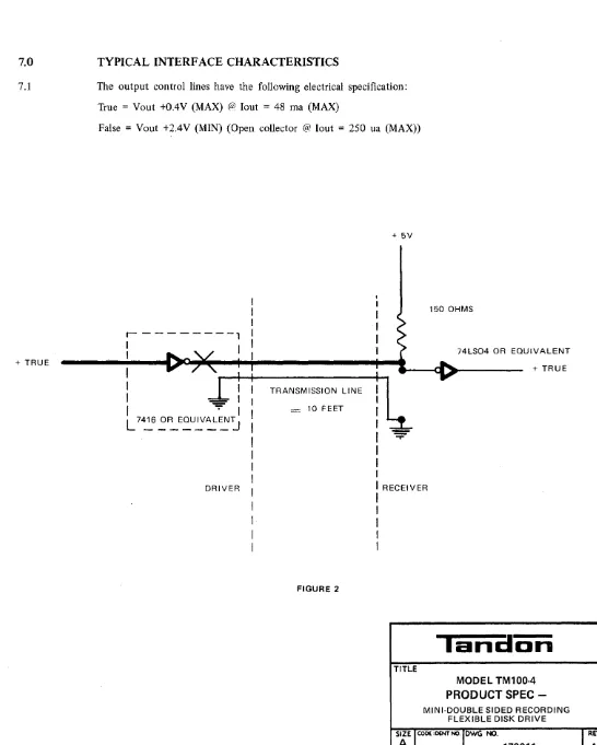
TYPICAL INTERFACE CHARACTERISTICS
The output control lines have the following electrical specification: True
=
Vout +0.4V (MAX) @2 lout=
48 rna (MAX)False
=
Vout +2.4V (MIN) (Open collector @ lout=
250 ua (MAX))+ 5V
I
I
,---1
!
i,~
(
I
I I
I ....
.-.'J
I150 OHMS
74LS04 OR EQUIVALENT
I
.,... /
'_-+--I+--!---+-.:--
~-"""(1111 ~
...
-I
I
I
I TRANSMISSION LINEi
+ TRUE
I
-:::b
I II
~I
=
10 FEETI
L7~6 ~~EQU.::'AL~j
I _
10:;::-I
I
I
DRIVER
I
RECEIVERFIGURE 2
I
I
I
I
I
TITLE
lani:lon
MODEL TM100-4
PRODUCT SPEC
-MINI-DOUBLE SIDED RECORDING FLEXIBLE DISK DRIVE
SIZE
1
COOl I DENT NO. OWG NO.A
179011REV
[image:14.618.39.585.75.756.2]REVISIONS
DESCRIPTION DATE DR CHI( APPR
SEE PAGE 1
I
~
---~JpS---POWER ON _ _ ..J.
MOTOR ON _ _
:-=1_
... _
~~---~IS~---DRIVE SELECT _ _ _ _
-+ __ ..
s
VALID TRK. 00
AND WRT. P R O T . - - - -...
--+--i
OUTPUT~---~,~---VALID INDEX/
SECTOR OUTPUT
....
~I----~ 250 MSEC MAX
~---~sP---~500 ns MAX DIRECTION _ _ _ _ ... _ _ _ ....
SELECT
STEP----~---~
I ....
I
3MS MIN~---~~f---I--..
1 Us MIN~
---i
~900
USEC MIN18 MS MIN
WRITE ENABLE---~---~---~~ _ _ _ _ _ _ 4 ~
... - - - 250 MSEC--~----' WR ITE DATA
---+o ...
---t'----....;, ...
VALID 18 MS MIN
[image:15.618.46.578.30.548.2]READ DATA ________ ... _________________________ ~
... - - - - 2 5 0 MSEC ...
I
MAX
~900
Us MINt---UlJ
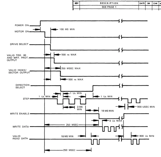
MODEL TM-100 GENERAL CONTROL AND DATA TIMING REQUIREMENTS
FIGURE 3
TITLE
lanaon
MODEL TM100-4
PRODUCT SPEC -MINI-DOUBLE SIDED RECORDING
FLEXIBLE DISK DRIVE
SIZE CODE I DENT NO. DWG "'fO.
A
SCAlE
REV