Texture-based Image Retrieval Using
Multiscale Sub-image Matching
Mohammad F.A. Fauzi and Paul H. Lewis
Department of Electronics and Computer Science, University of Southampton,
Southampton, United Kingdom
ABSTRACT
The paper presents research on a robust technique for texture-based image retrieval in multimedia museum collections. The aim is to be able to use a query image patch containing a single texture to retrieve images containing some area with similar texture to that in the query. A retrieval technique without the need for segmentation is presented. The algorithm uses a multiscale sub-image matching method together with an appropriate texture feature extractor. The multiscale sub-image matching is achieved by first decomposing each database image into a set of 64×64 pixel patches covering the entire image. The resolution of the database image is then rescaled to create sub-images corresponding to a larger scale. The process continues until the final resolution of the image is equal to some pre-determined value. Finally, a collection of sub-images corresponding to different image regions and scales is obtained. The final image feature vector consists of a collection of feature vectors corresponding to each sub-image. Several wavelet-based feature extractors are tested with the multiscale technique. From the experiments, it is found that the multiscale sub-image matching method is an efficient way to achieve effective texture retrieval without any need for segmentation.
Keywords: Texture feature extraction, multiscale, sub-image matching, content-based retrieval, wavelet
transform
1. INTRODUCTION
Image retrieval has been a very active research area since the 1970s, with the thrust from two major research communities; database management and computer vision.1 Image retrieval can be divided into text-based image retrieval (TBIR) and content-based image retrieval (CBIR). The text-based technique first annotates the images with text, and then uses text-based database management systems to perform image retrieval. The use of text-based image retrieval was very popular in the early days of computer vision, but its usage has been less dominant in recent years. There are two major factors that contribute to this; the vast amount of labour required in manual image annotation and the subjectivity of human perception. This leads to more efforts being required on content-based image retrieval. Using this technique, images are indexed by their own visual content, such as colour, texture or shape. CBIR has become more and more important with the advance of computer technology, and potentially should provide the answer to the two drawbacks of the TBIR system mentioned above.
Among many retrieval features associated with CBIR, texture retrieval is one of the most difficult. This is mainly because no satisfactory quantitative definition of texture exists at this time. Texture analysis has a long history and texture analysis algorithms range from using random field models to multiresolution filtering techniques such as the wavelet transform. Unlike colour, texture cannot be represented by a single pixel, making texture analysis a very challenging field. One way to perform content-based image retrieval using texture as the cue is by first segmenting an image into a number of different texture regions and then performing a texture analysis algorithm on each texture segments. However segmentation can sometimes be problematic for image retrieval.2 In this paper, we propose a simple but effective algorithm for texture-based image retrieval without the need for segmentation. Our algorithm uses a multiscale sub-image matching method together with an appropriate texture feature extractor.
Further author information: (Send correspondence to M.F.A.F)
Divide image into several 64x64 sub-images
Get a sub-image, and compute its feature vector
Add sub-image's feature vector to the final feature vector
Finish with all sub-images?
Row or column size of image is 64?
No
Yes
No
Yes
Final Feature Vector Half image by
a factor of j/i, where:
i=smallest(row,column), j=nearest dyadic integer to i,
j<i
[image:2.594.143.451.115.424.2]Image
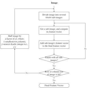
Figure 1. Flow chart of the multiscale algorithm.
The idea of a multiscale feature extraction technique has found much success in the area of colour analysis. One example can be found in Chanet al’s work,3 where they use the multiscale approach to extract colour features using the colour coherence vector (CCV) technique. The resulting algorithm, which they call a multiscale colour coherence vector (MCCV), manages to handle the problem of sub-image colour retrieval effectively, without the need for any segmentation. With minor modification, the multiscale approach can be used in the same way to extract texture information using any texture feature extraction method, although the ones with low computational load are preferable. In this paper, three wavelet-based feature extraction methods are tested with the multiscale technique, namely the pyramid-structured wavelet transform (PWT), the tree-structured wavelet transform (TWT), and the discrete wavelet frames (DWF). Wavelet-based feature extractors are chosen because of their high classification accuracy and low computational load.
This paper is organized as follows. Section 2 describes the multiscale algorithm, while section 3 presents the overview of wavelets and the three different feature extractors to be tested with the multiscale algorithm. Section 4 describes the experimental details followed by results and evaluation. Finally the conclusions and future work are presented in section 5.
2. MULTISCALE ALGORITHM
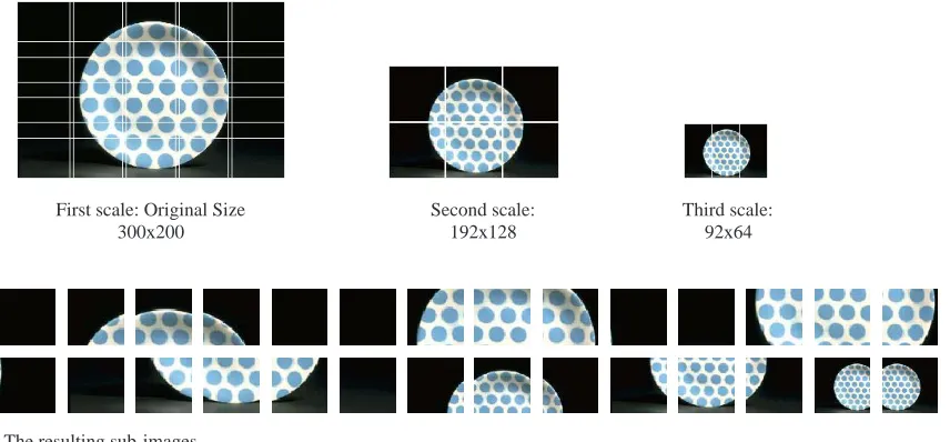
300x200 192x128 92x64
[image:3.594.86.514.114.313.2]The resulting sub-images
Figure 2. Example of sub-image tiling.
applying the multiscale technique. The 64×64 sub-image regions will then be very easy to determine due to the dyadic nature of the image size. To process the image at a different scale, the current image resolution is simply halved in each dimension. The process continues until either the row or the column of the image is of size64.
The above condition however might be suitable for colour features, but might not work for texture features. By non-linearly re-scaling the resolution of the input image, the texture characteristics of the image might be affected, and features extracted from it might not reflects an accurate representation of the texture, hence resulting in incorrect retrieval. Because of this, we will not apply the above dyadic re-scaling in our multiscale algorithm. Instead, we begin our multiscale algorithm from the original size of the input image. Because of the possibly non-dyadic nature of the image size, we will end up with a collection of slightly overlapping 64×64 sub-images at the current resolution. The total number of sub-images for a particular scale is calculated by:
number of sub-images = ceil
number of row pixels
64
×ceil
number of column pixels
64
. (1)
A suitable texture feature extraction can now be performed on all sub-images separately. Each time a feature vector of a sub-image is produced, it is added to the final feature vector, which represents the multiscale feature vector of the parent image. After all sub-images of the current scale have been processed, the image is linearly rescaled and the whole process is repeated. To find the resolution of the image at the next scale, we first find the smallest value,i between the number of row pixels and the number of column pixels at the current scale, compute the nearest dyadic integer to that value,j, and then linearly rescale the image by a factor ofj/i. Starting from this level onwards, to go to the next scale, we simply rescale the image by a factor of half. The process stops once either the row or column of the image is of size64. The final feature vector, which consists of a collection of feature vectors corresponding to different regions and scales, is saved. Fig. 2 shows an example of the sub-image tiling.
3. WAVELET-BASED TEXTURE FEATURE EXTRACTORS
Wavelets were invented to overcome the shortcomings of the Fourier Transform. The fundamental idea is not only to analyse according to frequency but also according to scale, which is not covered by the Fourier transform. Most standard wavelets are based on the dilations and translations of one mother wavelet,ψ, which is a function with some special properties.
In image processing terms, the dilations and translations of the mother functions ψ are given by the wavelet basis function:
ψ(s,l)(t) = 2−s/2ψ(2−sx−l).
The variabless and l are integers that dilate and orientate the mother function ψ to generate a family of wavelets, such as theDaubechies wavelet family.4 The scale index s indicates the wavelet’s width, and the location indexl gives its position in 2-D.
Wavelets can be divided into orthogonal and non-orthogonal. They are orthogonal if their basis functions are mutually orthogonal. Because of the orthogonality, there exist a series of coefficients that can represent the wavelet decomposition for the whole family of a particular wavelet. The series of coefficients is named the
quadrature mirror filter(QMF). This concept, along with the theory of filter banks, is the basis for producing the famous fast algorithm wavelet transform by Mallat.5
Quadrature mirror filter is a filter that can be either low-pass or high-pass just by changing sign and rearranging its coefficient as below:
lowpass : [ c0 c1 c2 c3 ],
highpass : [ −c3 c2 −c1 c0 ],
(2)
wherec0,c1,c2 andc3 are the coefficients of a 4-tap filter.
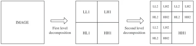
In 2-D wavelet decomposition, the QMFs are used as both highpass and lowpass in both horizontal and vertical directions, followed by a 2 to 1 subsampling of each output image. This will generate four wavelet coefficient images, i.e. thelow-low,low-high,high-low andhigh-high(LL,LH,HL,HH respectively) channels. The process is then repeated until some pre-determined condition is met. For detailed information on wavelet theory, readers are referred to the references.6–8
Features are computed from each of the channels of the wavelet transform output. The mean µ of the magnitude of the transform coefficients is used to calculate the features. Let the output channel be Wmn(x, y) andmn denotes the specific channel, wherem is the decomposition level andn=1,2,3,4 indicates theLL,LH,HLandHH bands respectively, thenµmnis calculated by:
µmn= 1
Nmn2 |Wmn
(x, y)|dx dy, (3)
whereN is the length of a particular channel mn.
3.1. Pyramid-structured Wavelet Transform (PWT)
The pyramid-structured wavelet transform is the initial decomposition structure of wavelet transform and was developed by Mallat.5 In PWT, the decomposition process is continued in the LLchannels only until some predetermined condition is satisfied. An example of a 2-level decomposition of an image is shown in Fig. 3.
The number of channels, hence the number of features for PWT is given by:
number of channels= 3×l−1, (4)
IMAGE
LL1 LH1
HH1 HL1
HH2 HL2
LH1
HH1 HL1
First level decomposition
[image:5.594.129.464.109.190.2]Second level decomposition
Figure 3. PWT decomposition of an image.
3.2. Tree-structured Wavelet Transform (TWT)
In TWT, the decomposition process is not restricted to theLL channels only, but also in specific circum-stances, onLH,HL andHH channels as well. This results in a richer range of possibilities for analysis. The reason for using TWT in texture analysis is because the dominant frequencies of textured images do not only lie in the lower resolution band, but perhaps in the middle band as well.9 Thus TWT helps in providing the platform to analyse texture information in the middle frequency band. To avoid full decomposition, various ways are suggested to determine which channels are suitable for further decomposition. One popular method is to use an energy measure, where only sub-images with energy above a certain threshold are decomposed further. However this results in a much complex algorithm. Our tree-structured wavelet transform follows the one suggested by Ma and Manjunath,10 where theLL,LH andHLchannels are decomposed further at every level. TheHH channel is not decomposed as this often does not lead to stable features. Fig. 4 shows a 2-level TWT decomposition of an image.
IMAGE
LL1 LH1
HH1 HL1
LL2
HH2 HL2
LH2
HH1
First level decomposition
Second level decomposition
LL2
HH2 HL2
LH2
LL2
HH2 HL2
LH2
Figure 4. TWT decomposition of an image.
The number of channels, hence the number of features for TWT is given by:
number of channels= 4×3l−1+ 3l−2+...+ 30, (5)
wherelis the number of decomposition level, andl >0.
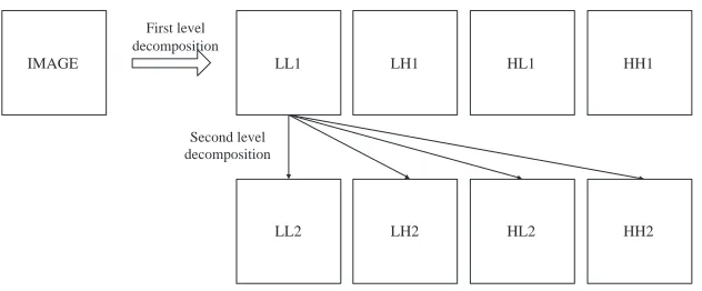
3.3. Discrete Wavelet Frames (DWF)
DWF, or over-complete wavelet transform, is nearly identical to the standard wavelet transform (PWT), except that one upsamples the filters, rather than downsampling the image. While the frame representation is over-complete, and computationally more intensive than PWT, it holds the advantage of being translationally invariant.11
Given an image, the DWF decomposes it using the same method as the PWT, but without the subsampling process. This results in four filtered images with the same size as the input image. The decomposition is then continued in theLLchannels only as in PWT, but since the image is not sub-sampled, the filter has to be upsampled by inserting zeros in between its coefficients. Fig. 5 shows a 2-level DWF decomposition of an image.
The number of channels, hence the number of features for DWF is given by:
number of channels= 3×l−1, (6)
[image:5.594.133.464.386.464.2]IMAGE LL1
LL2
HH1 HL1
LH1
LH2 HL2 HH2
First level decomposition
[image:6.594.141.457.109.240.2]Second level decomposition
Figure 5. DWF decomposition of an image.
4. EXPERIMENT
4.1. Experiment Details
The multiscale algorithm together with the three feature extraction techniques were tested on a collection of museum images, where each image may or may not contain a certain amount of texture within them. The total number of images in the test collection is 1106, with sizes ranging from 341×512 to 958×648. The performance of the proposed method will be evaluated based on the ability of the algorithm to retrieve images which contain a texture region similar to the query image patch.
The combination of the multiscale algorithm with PWT, TWT and DWF are called multiscale-PWT (MPWT), multiscale-TWT (MTWT) and multiscale-DWF (MDWF) respectively. A summary of parameters used for each technique is described below:
MPWT: decomposition level = 2, filters =Daubechies 8-tap wavelets, feature vector size per sub-image = 7;
MTWT: decomposition level = 2, filters =Daubechies 8-tap wavelets, feature vector size per sub-image = 13,
decomposition structure = fixed onLL,LH andHL channels;
MDWF: decomposition level = 2, filters =Daubechies 8-tap wavelets, feature vector size per sub-image = 7;
TheDaubechies8-tap wavelet filters were chosen because they are compactly supported and well localized in both the time and frequency space. An 8-tapDaubechies wavelet filter coefficients are given by:
lowpass : [ −0.0106 0.0329 0.0308 −0.1870 −0.0280 0.6309 0.7148 0.2304 ],
highpass : [ −0.2304 0.7148 −0.6309 −0.0280 0.1870 0.0308 −0.0329 −0.0106 ]. (7)
For each technique, the mean energy as described previously is used to form the feature vectors. The distance measure used is the Euclidean distance. The distance between 2 featuresi andj is then given by:
d(i, j) = m
n
µ(mni) −µ(mnj) 2
. (8)
Since all images used in this experiment are colour images, the feature extractor is applied on the lumi-nance value of the images. The lumilumi-nance of an image can be computed using the formula:
1 2 3 4 5 Query image
1 2 3 4
1 2 3 4
MDWF MTWT
[image:7.594.69.525.118.387.2]5 5
Figure 6. Retrieval result using query image 1.
whereR, G, B are image components corresponding to red, green and blue respectively. It is important to note that the PWT, TWT and DWF algorithms are mainly a texture descriptor algorithm and therefore the retrieved images might not be in a correct colour order. The correct colour order might be achieved by integrating the texture descriptor with some colour descriptor such as the histogram RGB method but it is beyond the scope of this paper.
Also, to reduce the bias caused by different illuminating conditions, the local mean is subtracted from each sub-image before applying the feature extractor. For the query image, the image is first resized to 64×64 before a particular feature extractor is applied. No multidimensional indexing is used although it is intended that the process will be accelerated by its introduction.
4.2. Result and Discussion
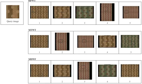
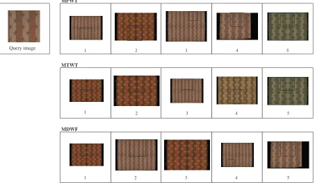
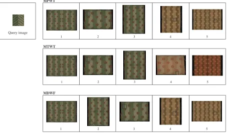
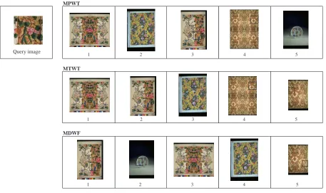
Figs. 6, 7, 8 and 9 show four examples of retrieval results for each wavelet technique using 4 different query patches. The query image along with the top five retrieved images are shown. The box in the retrieved image indicates that the sub-image is computed to be the most similar to the query image.
It is difficult to make a precise comparison between the performances of the three wavelet-based techniques using the multiscale approach. This is because most of the images retrieved are the same for all three techniques but with different order. However , as illustrated in the four examples shown, a fair conclusion can still be made. Fig. 6 shows a very good retrieval results for all three methods. All images which contain a region with the same texture as the query were retrieved in the top 5, regardless of its resolution. In Fig. 7, the same texture but with a different colour and resolution is used, and the retrieval result again shows that the correct images are retrieved.
1 2 3 4 5 Query image
MDWF MTWT MPWT
1 1
2 2
3 3
4 4
[image:8.594.73.526.119.383.2]5 5
Figure 7. Retrieval result using query image 2.
MPWT and MDWF techniques does not have significant difference except that since MDWF is tanslationally invariant, the marked regions in the retrieved images are more relaxed, hence the marked region might show a quite different texture translation from the one in the query. This is clearly shown in Fig 8 where the first retrieved image using MDWF shows the same texture but with different texture direction. Fig. 9 shows a result of using a completely different texture patch. All the algorithms manage to find a region in an image that has more or less the samebusy pattern as in the query, even a very small graphic on a plate, as shown in the second retrieved image of MDWF.
The main conclusion that can be taken from this experiment is that the multiscale method can be used to retrieve texture without segmentation. There is not enough space to show all the retrieval results, but generally the multiscale technique together with one of the three wavelet-based techniques, works very well in retrieving textures. Although in some cases there are also some rather unfamiliar texture patterns retrieved, that is not very crucial as long as all the wanted texture patterns are retrieved within the top matches. The result also shows that the multiscale approach does manage to tackle the scale invariance problem, where images with the same texture but with different resolution are retrieved together.
Image Size 768 x 512 958 x 648
(128 sub-images) (293 sub-images)
MPWT 1.5 3.2
MTWT 2.9 6.3
[image:8.594.184.417.610.675.2]MDWF 8.5 18
Table 1.Time (in seconds) taken to extract features for a single image. Image size 768×512 is the most used in the experiment, while image size 958×648 is the largest.
1 2 3 4 5 Query image
MDWF MTWT
1 1
2 2
3 3
4 4
[image:9.594.73.526.118.384.2]5 5
Figure 8. Retrieval result using query image 3.
the PWT, TWT and DWF are applied several times for each image, the computation is performed on a sub-image of size 64×64, which takes just a fraction of a second. The computational speed of the multiscale algorithm is therefore an advantage since segmentation-based texture retrieval could take a longer time just to segment the image.
5. CONCLUSIONS AND FUTURE WORK
In this paper we have proposed a modified multiscale algorithm to be used in texture-based image retrieval. We have shown that the multiscale algorithm does not only work with colour retrieval, but given a suitable texture descriptor, it can provide a very good texture retrieval platform as well. The retrieval accuracy of the algorithm is excellent and further improvement to the algorithm should result in a very good texture retrieval system. The computational load of the algorithm is also beneficial, as a segmentation-based texture retrieval might take longer just to segment the image. In terms of performance comparison between the different feature extractors, the MTWT technique gives a slightly better result than the MPWT and MDWF.
We are working on improvements to the algorithm, the multiscale algorithm is to be applied on both the query image and the database images. Also, to improve the performance, creating more sub-images from a single image might help. However these improvements have to come together with a suitable indexing system as well as fast matching algorithm since the more sub-images produced, the more the feature vectors and the more time it will take to perform feature matching. Texture retrieval with a correct colour order will also be addressed.
ACKNOWLEDGMENTS
1 2 3 4 5 Query image
MDWF MTWT MPWT
1 1
2 2
3 3
4
4 5
[image:10.594.71.528.115.386.2]5
Figure 9. Retrieval result using query image 4.
REFERENCES
1. Yong Rui and Thomas S. Huang, “Image retrieval: Current techniques, promising directions, and open issues,”Journal of Visual Communication and Image representation,vol. 10, pp. 39–62, 1999
2. Yossi Rubner and Carlo Tomasi, “Texture-based image retrieval without segmentation,”Proceedings of the 7th IEEE International Conference on Computer Vision, vol. 2, pp. 1018–1024, 1999
3. S. Chan, K. Martinez, P. Lewis, C. Lahanier, and J. Stevenson, “Handling Sub-Image Queries In Content-Based Retrieval of High Resolution Art Images,” Proceedings of International Conference on Cultural Heritage and Technologies, pp. 157–163, 2001
4. Amara Graps, “An introduction to wavelets”, IEEE Computational Science and Engineering, vol. 2, pp. 50–61, 1995
5. Stephane G. Mallat, “A theory for multiresolution signal decomposition: The wavelet representation”,
IEEE Transactions on Pattern Analysis and Machine Intelligence,vol. 11, pp. 674–693, 1989
6. Ingrid Daubechies, “The wavelet transform, time-frequency localization and signal analysis”,IEEE Trans-actions on Information Theory,vol. 36, pp. 961–1005, 1990
7. Thong Ngunyen and Dadang Gunawan, “Wavelet and wavelet-design isuues”, Proceedings of ICCS, pp. 188–194, 1994
8. Stephane Mallat, “Wavelets for a vision”,Proceedings of IEEE,vol. 84, pp. 604–614, 1996
9. Tianhorng Chang and C.C. Jay Kuo, “Texture analysis and classification with tree-structured wavelet transform”,IEEE Transactions on Image Processing,vol. 2, pp. 429–441, 1993
10. W. Y. Ma and B. S. Manjunath, “A comparison of wavelet transform features for texture image annota-tion,”Proceedings of IEEE International Conference on Image Processing, vol. 2, pp. 256–259, 1995 11. Michael Unser, “Texture classification and segmentation using wavelet frames”,IEEE Transactions on