© 2016, IRJET | Impact Factor value: 4.45 | ISO 9001:2008 Certified Journal | Page 1445
Power System Stability Using Unified Power Flow Controller
Sonal M. Adhau
1, Dinesh D.Majumdar
2Electrical Engineering Department ,Shri Sai College of Engineering & Technology Bhadrawati, Electrical Engineering Department ,Shri Sai College of Engineering & Technology Bhadrawati,
Maharashtra (India).
---***---Abstract -
UPFC is one of the most widely used FACTS devices. To control (Kw) and (Kvar) in power system FACTS devices are usually used. In this paper case study of 9 bus system is considered under the three phase to ground fault in MATLAB Simulink. Active power, reactive power and rotor angle, angular speed during the fault is analyzed.Key Words:MATLAB-Simulink, UPFC
1.INTRODUCTION
In recent year the technology is advances so that transmission network reliable and easy to design. There are many technologies in interconnected power system such as, HVDC and EHVAC. On other side as power system network grow, the interconnected network become increasingly more composite to operate and system can be less protected for riding through the major outages. The power system interconnected network of today is large and complex. There is widely use of microelectronic, computers and high speed communication for control and protection of present interconnected system. The main purpose of FACTS is to improve system controllability and to increase power system bound by using power automated devices. Generally, FACTS devices are more expensive than HVDC devices. In case study consists of 3 generators nine bus system having three load and three transformer. The single line diagram of nine bus system as shown in fig. 1.It is simple diagram of power system to analyzed dynamic behavior and also power oscillation damping. In this system three phase fault is occurs at bus 8.Duration of fault time is 4 to 4.1 sec. After 4.1 sec. the fault is remove system try to maintained stability, also active power, reactive power and bus voltage of different buses is calculated.
The UPFC consists of two branches. The series branch consists of a voltage source converter, which injects a voltage in series through a transformer. The inverter at the input end of the UPFC is connected in shunt to the AC power system and the inverter at the input end of the UPFC is connected in series with the AC transmission circuit.
2.
ASSUMPTION IN TRANSIENT STABILITYI) Mechanical input given to the synchronous generator will be constant.
II) Effect of damper winding can be neglected.
III) The voltage at generator and at the bus are assumed to be constant.
IV) Angular velocity of synchronous machine will be assumed as constant.
Fig.1 Single Line Diagram of 9 Bus System
Single line diagram consist of 9 bus power system having generator, load, transformer and transmission line having length 50km. UPFC is connected between buses 7 and 5. Three phase to ground fault takes place at near to the bus no.4. Duration of fault is 0.1 sec. After 4.1 sec. the fault is removed.
© 2016, IRJET | Impact Factor value: 4.45 | ISO 9001:2008 Certified Journal | Page 1446
3. UPFC
Static power electronics device consist of capacitor and inductor etc. are used for compensation. So after introduction of FACT devices give a control on the compensation. FACT devices like STATCOM, SVC, and SSSC.
The UPFC can control the transmission real power, at its series-connected output end, while independently providing reactive power support to the transmission line at its shunt connected input end. It is to control the flow of KW and KVAR by inoculation of a voltage in
series with the transmission line. Magnitude of voltage
and the phase angle of the voltage can be diverse
independently.
To optimize the cost and optimum use of transmission line compensation is needed, which can either, compensate the voltage, phase shift, or both the increase of voltage and phase shift, and real and reactive power enhancement. Before the introduction of static power electronics device, fixed capacitor, inductor etc. are used for compensation over which control could not be done, .So some controller should need to be used which can give both series and shunt compensation.
4. STATCOM (Static Synchronous Compensator)
AC Voltage Measurement
AC Voltage Regulator
DC Voltage Regulator current Measurement PLL
PWM Modulator
DC Voltage Measurement
VSC
Current Regulator
V1
I
Vref
Vac
V1dq
Id
Iq
Iqref
Idref
Id
Iq
V2d
V2q
Vdc
Vdcref
Pulse +
-+
-- +
+
V1dq
Vdc
I
Fig.2 Schematic Diagram of STATCOM
The shunt converter worked as STATCOM. The shunt inverter controls the ac voltage and voltage of dc bus. It uses a two voltage parameter loop inner current control loop and outer loop regulating AC and DC voltages. The control system contains: A phase-locked loop which synchronizes on the positive sequence
component of the three phase primary voltage V1 . The
output of the PLL is used to calculate the direct axis and quadrature axis component of the three phase voltage
and current. Measurement system measured the Vd
and Vq component of ac positive sequence voltage and
current which can be measured as well as the DC link
voltage Vdc.
An outer parameter loop comprising of an AC voltage regulator and DC voltage regulator. The output
of the ac voltage regulator is the ref. current Iqref for the
current regulator. The o/p of the DC voltage regulator
is the ref. current Idref for the current regulator. The
current regulatory control the magnitude phase of voltage generating by the pulse width modulation inverter.
5. SSSC (Static Synchronous Series Compensator)
Voltage Measurement
Current Measurement
Vq Voltage
Regulation
Vd Voltage
Regulation
PQ Measurement
PWM Modulation PLL
Qref
Pref
Vd
Vq
VSC pulse
V2
V1
I
P
Q
Voltage injection
auto Vdref
Vqref
ᶿ ᶿ
+
-+
-Fig.3 Schematic Diagram of series inverter
It controls the series branch which is different from the SSSC. In the SSSC the two degree of freedom of the series converter is used to control the DC link voltage and reactive power. In case of a UPFC the two degree of freedom is used to control the active power and the reactive power.
The series inverter may operate either in power flow control the measured active power kw and reactive
power kvar are compared with value to produce Pref
and Qref. The P and Q error are used by two P.I.
regulators to calculate the Vq and Vd component of
© 2016, IRJET | Impact Factor value: 4.45 | ISO 9001:2008 Certified Journal | Page 1447
6. SIMULINK MODEL
Fig.4 Simulation Diagram of 9 Bus with UPFC System
7. SIMULATION RESULT
The MATLAB simulation result of the power system is shown in the figure given below. The three phase to graund fault takes in between 4 to 4.1 sec. After 4.1 sec the fault is removed. Also Active Power, Reactive Power and Bus Voltage are analyzed.
0 2 4 6 8 10 12 14 16 18 20
-500 0 500 1000 1500 2000 2500
Time
A
C
T
I
V
E
P
O
W
E
R
P B4 B5 B6 B7 B8 B9 (MW)
Fig.5 Active Power of Bus no.4 without UPFC
0 2 4 6 8 10 12 14 16 18 20
-200 0 200 400 600 800 1000 1200 1400 1600
Time
R
E
A
C
T
I
V
E
P
O
W
E
R
Q B4 B5 B6 B7 B8 B9 (Mvar)
Fig.6 Reactive Power of Bus no.4 Without UPFC
0 2 4 6 8 10 12 14 16 18 20
0 0.5 1 1.5 2 2.5 3 3.5 4
Time
B
u
s
V
o
lt
a
g
e
(
p
u
)
Bus 4 Bus 5 Bus 6 Bus 7 Bus 8 Bus 9
Fig.7 Bus voltage without UPFC
0 2 4 6 8 10 12 14 16 18 20
0.995 1 1.005 1.01 1.015
w
1
w
2
w
3
(p
u
)
w1 w2 w3 (pu)
0 2 4 6 8 10 12 14 16 18 20
0 0.5 1 1.5
V
t
1
V
t2
V
t
3
(
p
u
)
Vt1 Vt2 Vt3 (pu)
0 2 4 6 8 10 12 14 16 18 20
0 10 20 30 40
Time dt
h
e
ta
12
(
d
e
g
)
d_theta1_2 (deg)
M/C 3 M/C 2 M/C 1
M/C 3 M/C 2
© 2016, IRJET | Impact Factor value: 4.45 | ISO 9001:2008 Certified Journal | Page 1448
0 2 4 6 8 10 12 14 16 18 20
-500 0 500 1000 1500 2000 2500
Time
A
C
T
I
V
E
P
O
W
E
R
P B4 B5 B6 B7 B8 B9 (MW)
Fig.9 Active Power of Bus no.4 with UPFC Using PI controller
0 2 4 6 8 10 12 14 16 18 20
-200 0 200 400 600 800 1000 1200 1400 1600
Time
R
E
A
C
T
I
V
E
P
O
W
E
R
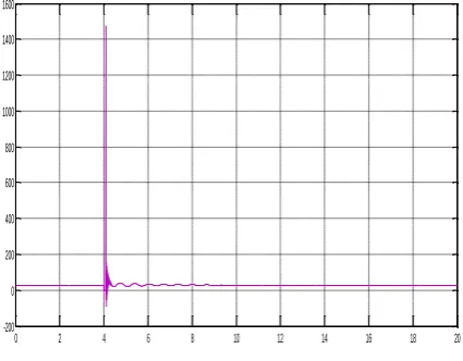
[image:4.595.62.275.110.251.2]Q B4 B5 B6 B7 B8 B9 (Mvar)
Fig.10 Reactive Power of Bus no.8 With UPFC Using PI controller
0 2 4 6 8 10 12 14 16 18 20
0 0.5 1 1.5 2 2.5 3 3.5 4
Time
V
p
o
s
.
s
e
q
.
Vpos. seq.
[image:4.595.323.541.115.310.2]Bus 4 Bus 5 Bus 6 Bus 7 Bus 8 Bus 9
Fig. 11 Bus Voltage with UPFC
0 2 4 6 8 10 12 14 16 18 20
0.995 1 1.005 1.01 1.015
w
1
w
2
w
3
(
p
u
)
w1 w2 w3 (pu)
0 2 4 6 8 10 12 14 16 18 20
0 0.5 1 1.5
V
t
1
V
t
2
V
t
3
(
p
u
)
Vt1 Vt2 Vt3 (pu)
0 2 4 6 8 10 12 14 16 18 20
0 10 20 30 40
Time
d
t
h
e
t
a
12
(
d
e
g
)
[image:4.595.63.276.313.479.2]d_theta1_2 (deg)
Fig.12 Angular Speed, Generator voltage and Rotor Angle With UPFC Using PI controller
8. CONCLUSIONS
From comparative study of the relative variation in rotor angle and angular speed of the three machines nine-bus system is analyzed. Also active power and reactive power of bus is done. By using a UPFC we obtain better transient stability performance than the case without a UPFC.
9. APPENDIX
MACHINE RATINGS
Sr.
no
Generator
Transformer
1 247.5MVA/16.5KV 250MVA,16.5Kv/230k
V
2 163.2MVA/18 kV 165MVA,18Kv/230kV
3 85MVA/13.8 kV 110MVA,13.8Kv/230V
REFERENCES
[1] N.G. Hingorani, L.Gyugyi “Understanding FACTS: concepts an technology of flexible AC transmission systems”, New York. 2000.
© 2016, IRJET | Impact Factor value: 4.45 | ISO 9001:2008 Certified Journal | Page 1449 Controller and Fuzzy Theory” PEDS 2009 MIAOLI6003,
TAIWAN.
[3] S. Prabaharan, M Lakshmanan ,” Enhancement of Transient Stability in a 9 Bus System using Matrix Converter Based UPFC ”, International Journal of Science and Research Volume, April- 2014.
[4] H. Rafiq, Salman Shakeel, Saleem N. Muhammad, K. Bashir,” Control System Design of UPFC for Optimal Power Flow Control ”, International Conference on Open Source Systems and Technologies 2013.
[5] Gyugyi L., “Unified Power Flow Control Concept for Flexible AC Transmission Systems,” IEEE Proceedings, vol. 139, July 1992.
[6] P.Kumkratug,P.Laohachai, “Direct Methods of Transient Stability assessment of Power System with a SSSC”,Journal of Computer 2007.
[7] I.Papic , P.Zunko, D.Povh,”Basic Control of Unified Power Flow Controller,” IEEE Trans. On Power System,Vol.12, no.4 Nov.1997.