l:C
b
EINDHOVEN UNIVERSITY OF TECHNOLOGY.
DEPARTMENT OF ELECTRICAL ENGINEERING.
DIGITAL SYSTEMS DIVISION.
DESIGN OF AN INTELLIGENT WINCHESTER DISK CONTROLLER
by: H.P.M. van Eijkelenburg.
Report on the graduation project conducted by H.P.M. van Eijkelenburg under the authority of Prof. ir. A. Heetman.
Period: April 4, 1982 - March 17, 1983.
Coached by: ir. M.P.J. Stevens. ir. J.P. Kemper.
SUMMARY.
This report covers the design of an intelligent Winchester Disk Controller. In contrast with traditional controller de~igns, the Disk Operating System, generally resident at the Host computer, is integrated in the controller.
After an introduction concerning the characteristics and appli-cations of Winchester drives, the problems involved with inter-facing these drives to a host computer are discussed.
Chapter three presents the general concept which lead to the final design. A separation is made between hard- and software. The hardware consists of a Winchester Controller Module, rather than a random logic circuit, a processor system consisting of a 16 bit CPU and an lOP co-processor, buffer- and program memory and an interface to the Host computer.
Chapter five deals with the software involved in this project, in particular the Disk Operating Systems. The UNIX operating system was taken as a guide-line for this purpose.
Though no prototype was built and tested, some conclusions are drawn in the last chapter concerning the feasibility of the design and its advantages over traditional controller designs. In addition, some recommendations for follow-up are made.
KEYWORDS: Design, Disk controller, Winchester, munication, DHA, Hardware, Processor ware, Disk Operating System, UNIX.
Soft-CONTENTS.
Summary 1
Contents 2
1. Introduction · · . · · · · 5
1.1. Mass storage devices ··. 5
1.2. Winchester disk drives 6
1. 3 . Disk controller 7
2. Problem definition 8
2.1.1. 2.1.2. 2.1.3. 2.2. 2.3.
Disk controller operation 8
Controller functions 9
Conclusion 15
Disk Operating System 16
Project definition ' 17
3. Winchester controller concept 19
3.1. 3.1.1. 3.1.2. 3.1.3. 3.1.4. 3.2. 3.2.1. 3.2.2. 3.2.3. 3.2.4. 3.3. 3.4. 3.4.1. 3.4.2. 3.5. 3.5.1. 3.5.2. 3.6. 3.6.1. 3.6.2. 3.6.3. 3.6.4.
Controller hardware 19
Drive control unit 20
Processor system 20
Host interface unit 20
Memory system 21
Disk storage organization 22
Physical storage 22
File descriptor 25
Address informat ion 26
Index list 28
Directory structure 28
Free space administration 33
Free block pointer list 33
Bit map 36
Command structure 38
File handling commands 38
Directory commands 47
Host Interface 47
Network solution 48
Register solution 49
Bus solution 50
Conclusion 50
4. Controller hardware design 51 4.1. 4.2. 4.2.1 4.2.2. 4.2.3. 4.3. 4.3.l. 4.3.2. 4.3.3. 4.3.4. 4.4. 4.5. 4.5.l. 4.5.2. 4.5.3. 4.5.4. 4.5.5. 4.5.6. 4.6. 4.7. Introduction 51
Processor system 51
Parallel- versus co-processing 51
I/O processor description 55
Central processing unit description 55
Memory system 56
Dynamic RAM system 57
Static RAM system 59
ROM system , 60
Address decoding 60
Host interface 61
Drive control unit hardware . . . • . . . • 63 Standard log ic . . . • . . . 63
Programmable logic 63
Single chip controller 63
Processor module interface 65
DMA transfer timing 71
DMA termination 76
Drive interface 76
Interface standards 78
5. Software description 79
5.l. 5.2. 5.3. 5.3.1. 5.3.2. 5.3.3. 5.3.4. 5.3.5. 5.4. 5.4.1. 5.4.2. 5.4.3. 5.5. 5.5.1. 5.5.2. 5.5.3. 5.6. 5.6.l. 5.6.2. 5.6.3.
Introduction . . . • 79
Initialization 80
Host protocol handler 88
Layer model 90
Application layer 91
Presentation layer 92
Transport layer . . . • . . . 93
Data link layer 98
Disk protocol handler . . . • . 101
Commands 101
Data 101
Task block program 102
Disk operating system 104
Command handler 104
Pree space administration 115
Pile management 121
Error handler . . . • . 122 Recoverable errors . . . • . . . 122
User errors 123
Patal errors . . . • . . . 123
6. Conclusions and recommendations ...•... 124
6.1. Conclusions 124
6.2. Recommendations 124
7. Acknowledgements 126
Literature reference list 127
Appendix A Appendix B Appendix C Appendix D
Hardware circuit diagrams 128
KSC 9000 data sheet 134
WD controller modules overview 145
PPLS based interface 149
Chapter 1. INTRODUCTION.
1.1. Mass storage devices.
Any user of a digital computer system will agree to the impor-tance of a reliable and fast mass storage device. This
back-ground memory is generally used to store user programs and
operating data in quantities too large to be kept in the compu-ters core memory. Demands imposed on such storage devices are:
Reliability, to ensure the correct retrieval of
stored information.
- Speed, to minimize delays caused by data access on the device.
- Cost-efficiency, meaning the price per unit of stored information should be as low as possible, typically far below the cost of a unit in core memory.
As these requirements are to some extent contradictory, severa1 compromises were made by storage device manufacturers.
Three important kinds of storage devices can be discerned, all of them based on magnetic storage techniques:
1. Disk drives. 2. Drum devices. 3. Tape units.
The first category is by far the most widely used and will be focussed upon in this report.
Within the range of disk types, a large variety exists, star-ting with 3 inch diameter micro floppy disks and ranging to hard disks.
The following table offers an overview of their capacity.
DRIVE TYPE. DIAMETER. STORAGE CAPACITY.
Floppy disk 3 inch 100
-
250 Kbyte.5.25 inch 125 -1000 Kbyte.
a
inch 250 -2000 Kbyte.Winchester disk 5.25 inch 2
-
10 Mbyte.a
inch 5-
40 Mbyte.1.4 inch 20 - 200 Mbyte.
Hard disk over 14 inch over 200 Mbyte.
---The choice of a certain type of disk drive will largely depend on its application. storage capacity will in most cases be the decisive factor allthough access-time and cost-effectiveness play an important role as well.
very recently, a growing trend towards the application of Win-chester drives has developed, espescially for small and medium sized computer systems. The traditional floppy disk drives, commonly found in these applications, are gradually replaced by Winchesters.
The explanation for this development is obvious. Due to finer and more accurate mechanical parts and new head materials, Win-chester drives have become a very favourable alternative to floppy disk drives in terms of storage capacity, access-time, reliability and more important, price per bit. It is for these reasons that this report will concentrate on Winchester drives.
1.2. Winchester Disk Drives.
The classification "Winchester" stands for a drive technology that employs a sealed disk and head-positioning assembly.
This eliminates the need for complicated and thus expensive air filtering provisions and air flow control required for hard disks.
The first Winchester type drive was develloped around 1973 by IBM, contained a double 30 Mbyte disk and was given type number 3030 as a result of that. This model number must have been associated by several people with the notorious Winchester double barrel riffle since this nickname was soon used and has been used for this drive technology ever since.
The major advantage Winchesters offer, as opposed to floppy disks, is the fact that the read/write heads fly above the disk surface on an air cushion, as is the case with hard disk drives. This air cushion is created by the speed of the disk in conjunction with the special shaped flexure, the flexure being the metal holder upon which the heads are mounted. The absence of physical head-medium contact enables faster disk speeds and associated data recording speeds. Presently, a recording speed of 5 Mbit/sec is quite common for the smallest Winchester drives.
Table II highlights some of the features of Winchester disk drives compared to floppy disk drives.
DIAMETER HEADS CAPACITY RECORDING TRACK
(inch) ( formatted) DENSITY DENSITY
FLOPPY 5.25 J. J.OO Kb 48 tpi
2 200 Kb
8 J. 500 Kb 96 tpi
2 J. Mb
WINCHESTER 5.25 2 5 Mb 6 J.O 255-980 tpi
4 J.O Mb 6 J.O 255-980 tpi
8 2 20 Mb 6 J.O 255-980 tpi
4 50 Mb 6 - J.O 255-980 tpi
Table II.
J..3. Disk controller.
Choosing a Winchester disk drive as a background mass-storage device, is not the complete solution to the problem. A link between the host computer and the drive will have to be esta-blished. This link is usually formed by a disk controller device. Either a disk controller is bought or it is developed and built by the purchaser of the drive. When buying a con-troller, the user has little or no knowledge of its operation and has to settle for a standard controller device. When desig-ning and building however, all customer specific demands and requirements can be taken into account, leading up to a flexi-ble customized controller.
The object of this graduation project was to design a control-ler, capable of controlling a wide range of Winchester drives and interfacing with an arbitrary host computer system.
Chapter 2. PROBLEM DEFINITION.
Introduction.
Prior to formulating the project covered in this report, a
survey of the functions performed by a traditional controller
is given. This will give a better insight into the problem at
hand. Subsequently, the position of the disk operating system
within a computer environment is discussed.
Equipped with this knowledge, the project definition is
formulated in the last paragraph of this chapter.
2.1. Disk Controller operation.
Looking at a conventional computer system which uses disks as
background memory, one can abstract a raw system model as is
done in figure 2.1.
Applicati on programs
:
disk operating system
controller'
...
.-drive drive
Figure 2.1: conventional computer system model.
The controller constitutes the link between what will henceforth be called the Host computer and one or more disk drives. For this purpose it entails a number of functional modules which will be described briefly in the next section.
2.1.2. Controller functions.
A functional block-diagram of a standard type disk controller is depicted in figure 2.2. In discussing the different modules we will distinguish between three kind of operations:
1. Disk write operations.
2. Disk read operations.
3. Drive control operations.
Disk write operations.
Serializer.
Data from the host is presented in either bytes or words, generally in a parallel format. Recording on the disk surface however is done serially, implicating the parallel data has to be serialized. The serializer performs this rather straight-forward operation by means of a parallel in/serial out shift register.
CRC generator.
To increase data integrity, a cyclic redundancy checksum is calculated and added towards the end of a block of data usually the size of one disk sector. This CRC control function enables verification of data upon reading and thus increases the reliability of the disk information.
Using CRC, the serial bits of information are treated as the coefficients of a binairy polynomial P(x). This polynomial is modified to an extent that makes it exactly divisible by a fixed polynomial G(x). The divisor G(x) is refered to as the generator polynomial. The modified polynomial, M( x) of all the data bytes in a block is added. The result of this addition is recorded at the end of the datablock on the disk.
The reason CRC is used as an error detection scheme, is because of its advantages over other methods. Some of these advantages are:
- all errors within n successive bits are detected. (n is the number of bits in P(x). )
- for even G(x), all errors with an odd number of bits in error are detected (50 % of all possible random errors) .
f---~~ step
r---'"
f\\\ I---~~ d i r ect ior/ control head se
r---~
~======>dr
i
ve s eA.
dr
i
vecan
t
roI f - - - [va
l'
1'Et--~--- rea dy
IE~---- track 0-status
IE_----
seek encIE_----
index'--~.----....J
data
U
xceIverI
-~
deserializer~
-
'"
lineE::--r ec eIve r s
IE--CRC
checkerphase
- locked
100p
~
MFM
precom- lin e--
~ ~serializer pensation drivers
r---I ---? encoder
T
r
-AM
~
CRC
-
I-generator gene rater
Figure 2.2: Controller function block diagram.
NRZ
FM
MFM
On top of this, CRC is efficient in that the number of control bits is relatively small compared to the number of data-bits.
MPM-encoder.
The format in which data from the serializer and the CRC generator is presented, is known as NRZ. (No Return to Zero). This format is unsuitable to cause flux reversals on the disk surface. Furthermore, timing information is stored on disk along with the databits to allow proper readback operation. To overcome this problem, a MFM-encoder is used, converting NRZ data and clock information into MPM data. (PM data
represen-tation is not discussed here since it is never used for
Winchester drives. )
Figure 2.3 gives a timing diagram of different data represen-tation waveforms used for disk storage.
o
I ,.-- I I " I ~ I r - - I
I
I I I I I I
I
I I I I I I I
I I I I I I I
I
,
I I I II I I
l
bi tcell ;1
t
data pulseposition~~----~)~II _
- clock pul s.e
Figure 2.3: Data representation waveforms.
MPM is generated from NRZ according to the following rules.
1. Every bitcell contains either a data pulse, a clock pulse or no pulse at all.
2. A logic 1 in NRZ is represented by a data pulse in the corresponding bitcell.
4. If the previous bitcell contained a data pulse, the clock pulse in the next bitcell is missing.
5. If the previous bitcell contained no data pulse, there will be a clock pulse in the next bitcell.
This scheme may seem confusing at first but it will no doubt become clear when reading the next paragraph on data reading.
Precompensation.
Due to the fact that the rotational velocity of the disk is uniform, there will be an increase in lineair velocity of the disk surface passing under the read/write head. This increase is proportional to the track number, the most inner track having the highest track number.
As a result of this, the spacing between subsequent flux reversals of data and clock bits becomes smaller on the inner tracks of the disk. (bit crowding). If the spacing becomes too small, adjacent flux reversals tend to influence each other, resulting in bit shifts.
During a read operation, the read/write head develops a current as it encounters a flux reversal caused by either a clock or a data bit. It takes a finite time for this current to reach its peak value. During this time, the disk surface passes on and the next flux reversal crowds under the head, resulting in its peak current being summed with the previous one. In effect, this means ·the bit is shifted from its proper location. Pigure 2.4 illustrates this effect.
read
i
curre-nt+-+
~t
Pigure 2.4: Bit shift
detection level
t~
Portunately, this effect is predictable and can be compensated
by pre-shifting the bits in the opposite direction. This pre-shifting is done by the pre-compensation circuitry. As soon as writing is done on inner tracks - tracknumber greater than a predetermined value - the recorded bits are shifted back (early write), not shifted (on time) or delayed (late write) by a small amounth of time. On reading back the recorded infor-mation, the bits will appear to be on time.
Address Mark genera~or.
As a rule, Winches~erdisks are sof~ sec~ored. Thus address
informa~ion concerning ~rack and se~or number has ~o be
recorded on ~he disk. This informa~ionis presen~ in ~he form
of iden~i~y fields or in shor~ ID-fiels. The combina~ion of an
ID-field and a Da~a field forms a sec~or. The s~ar~ of an IO field has ~o be de~ec~ableby ~he con~roller. For ~his purpose markers are presen~ called Address Marks or AM. Address Marks
dis~inguish ~hemselves from o~her b~es by means of a missing
clock pulse, i.e. a viola~ion of ~he MPH encoding rules. Refer ~o figure 2.5.
MFM
I , - - I I .--- 1
---
I... ~I
---
II I I
I I I
I
I
,
I I II
,
I I I I I II I I I
I
,
, I
I I I I
,
!
r - - I
-
I I Ir r - -
,
,
I I I I I 1
I I I I I I
I I I I I I
I I I I I
I
I I ( I I
I I
I
I
,
I 1,
I , I
I I
,
I I I I I II
,
I I~ I
~ I I
I I I I I
I
I I I I I
I I
,
I I II
I
,
I I II
I I
,
I I II I
CLOCK 0A
DATA A1
' - - - - missing clock pulse
Figure 2.5: Address Mark genera~ion.
The address mark genera~or ~akes care of ~his clock bi~
Suppression.
Line drivers.
To ensure dis~ortion-free ~ransmissionof MPH da~a be~ween
con~roller and drives, differen~ialline drivers are used. The
Disk read operations.
Phase locked loop.
The initial phase in the read process, consists of abstracting the timing information recorded on the disk. The most accurate method is to use a phase locked loop, consisting of a phase comparator, a low pass filter and a VCO. The VCO is constantly being adjusted by the information derived from the clock pulses on the disk. AS a result of this, the output of the VCO is in synchronization with the data stream from the disk.
Data separator.
The data separator, effectively a MPH to NRZ data converter, generates separate data and clock pulses from its MFM input
signal. The output of the forementioned VCO is used for
synchronizing this data separator.
Address Mark Detection.
To find the beginning of an Io-field, the controller has to search for an Address mark. The address mark detector triggers on a missing clock pulse in the MPH data stream. Depending on whether the AM belonged to an Io-field or a Data field, sub-sequent bytes are read and interpreted by the controller.
CRC check.
The next phase in the read process is the CRC check. The CRC checksum, calculated by the CRC check circuitry conform para-graph 2.1, is compared with the checksum read from the disk at the end of the data field. A mismatch will result in an error signal, indicating the received data block contains errors.
Deserializer.
As is suggested by the name, the deserializer performs the inverse function of the serializer, converting the serial NRZ data from the data-separator in 8 or 16 bit words.
Drive control operations.
of the most a number
control it. The below. The third section of the controller exists of
control and status lines that enable it to
mechanical parts of the drives connected to
commonly used control and status lines are listed
head assembly and direction
heads on any
step Direction
Head select
Drive select
Moves the head assembly one track.
Indicates the direction of the
movement. Combining the
step-signal allows positioning of the track of the disk.
Selects a single head of the head assembly for reading or writing.
Selects one particular drive in the daisy chain connected to the controller.
Ready
Track 0
Seek end
Write fault
Index
Indicates the drive is ready for operation. After a start-up, i t requires some time for the disk to reach its operating velocity. During this time the drive is not ready.
Indicates the heads are at track zero. This
sig-nal is required for head calibration after a
start-up or a reset.
Indicates the heads have reached their destina-tion and are stable after a head movement opera-tion.
As a result of an incorrect operation, more than one head has been selected for writing or write current is flowing through a deselected head. The index pulse signals the beginning of a track.
2.1.3. Conclusion.
The above presents a general overview of the most predominant
characteristics of a disk controller. A more detailed
discussion of this topic is considered superfluous since the
controller concept discussed in this report uses advanced
2.2. Disk opera~ing sys~em.
So far, we discussed ~he hardware prov1s10ns needed ~o connec~ one or more Winches~er drives ~o a hos~ compu~er. Using ~his hardware se~-up, ~he hos~ has ~he capabili~y ~o con~rol ~he drive and ~o s~ore and re~rieve da~a on a sec~or basis.
The next layer in ~he hierarchie of da~a s~orage lies be~ween ~his physical disk con~rol layer and ~he logical da~a s~ruc~ure of ~he hos~ compu~er.
Any user of ~he hos~ compu~er sys~em, wan~ing ~o manipula~e
da~a, does so by using a logical da~a s~ruc~ure. The mos~
com-mon s~ruc~ure is a file s~ruc~ure. Every colle~ion of da~a
i~ems ~ha~ mee~s a ce~ain forma~ is called a file. Piles can again be devided in~o one or more records.
To be able ~o read and wri~e files ~o and from a disk, a ~rans la~ion has ~o be performed be~ween a logical file or record and ~he physical sec~ors on ~he disk where ~he informa~ion con~ain ed by ~ha~ file or record will be s~ored. Consequen~ly, ~he hos~ compu~er has ~o have knowledge of ~he physical organiza-~ion of ~he disk.
pur~hermore, ~he hos~ compu~er has ~o supply ~he user wi~h an access mechanism ~ha~ allows easy reading, wri~ing and manipu-la~ing of files. Thus a se~ of commands ~he user can apply has ~o be provided by ~he hos~ compu~er.
Summarizing, one can lis~ ~he func~ions of ~his in~ermedia~e layer be~ween disk con~roller and hos~ compu~er as such:
- Pile s~ru~ure suppo~.
Pree disk space alloca~ion and adminis~ra~ion. - Pile direc~ory suppo~.
Pile manipula~ion suppo~.
Hencefo~h, ~he collec~ionof ~hese fun~ions will be referred ~o as Disk Opera~ing Sys~em (DOS), since ~hey allow ~he user ~o opera~e ~he disk.
Pigure 2.6. places the DOS layer in its context.
user application programs
disk operating
5ystem
disk controller ha rdware
disk drives
]
l
~HOST COMPUTER
DISK CONTROLLER
DRIVES
Pigure 2.6: DOS layer position.
2.3. Project definition.
Traditionally, the Disk operating System forms an integral part of the host computers' overall operating system, as indicated by figure 2.6.
appl ication prog rams
communication layer
disk operating system
I controller hardware
disk d ri ves
]
HOST COM PUTERDISK CONTROLLER
Figure 2.7: Intelligent Disk Controller position.
This constitutes a new approach towards controller design. Various responsibilities residing in the Host computer, are now being transferred to the controller. This should enable the controller to operate in conjunction with a large variety of host computers.
A further design requirement involves maximum universality of the controller towards different types of Winchester drives. The concept of the intelligent Winchester Disk Controller will be presented in the next chapter.
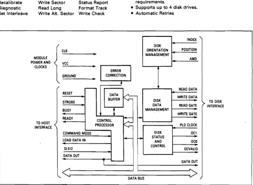
A summary of the system requirements is given below.
- Integrated Disk Operating System.
- High level communication between controller and Bost. - Support of multiple Winchester Drive types.
Chapter 3. WINCHESTER CONTROLLER CONCEPT.
3. Winchester Disk Controller Concept.
From the requirements mentioned in the previous chapter, two
subsytems can be deduced that constitute the Winchester Disk
Controller. The first subsystem is formed by the hardware,
which is drawn in figure 3.1. The second subsystem is the
software which operates the controller.
3.1. Controller hardware.
The hardware of the controller can be divided into four parts:
1. Drive control unit. (DCU)
2. Processor system. (PS)
3. Host Interface unit. (HIU)
4. Memory system. (MS )
host proce550r drive
-interface sy stem control
-
-unit unit
r
-me mory syste m
3.1.1. Drive Control Unit.
The drive control unit interacts directly with one or more Win-chester Disk Drives. Its functions include:
- Selecting the appropriate drive.
- Positioning the heads on a specified track. Pormatting soft sectored disks.
- Write sector.
- Address Mark Detection. Read sector.
as the forms In short, this is the part which is commonly regarded
actual disk controller. In our concept however, it only part of the integral controller.
3.1.2. Processor System.
The controllers processor system comprises three different major tasks:
1 DOS execution.
2 Communicating with the disk through the Disk Control Unit.
3 Communicating with the host computer system through the Host Interface Unit.
As the nature of these tasks allows for a division in proces-sing (1) and I/O (2,3), the processor system will be separated in two sections. One central processing unit will be used for executing the Disk operating system, a separate I/O processor will perform all neccessary communication between the Winches-ter Disk Controller, WinchesWinches-ter Drives and Host CompuWinches-ter.
3.1.3. Host Interface Unit.
Obviously some sort of connection has to be established between the controller and the Host Computer. Wether this connection exists of a parallel or a serial link is of no major importance at this stage. There are however some requirements this connec-tion has to meet:
of by
prevent the neccessity
data inconsistency caused - Maximum transfer speed of data to m~n~ze delays caused by records or files in transport between Host and Controller. Thus, either a parallel link with DMA capability or a high speed serial data link will be needed.
Reliability to retransmission or transmission errors.
mentations of such a communication link as these are to a large extent dependent on the Host computer used.
3.1.4. Memory System.
The Winchester Disk Controller's memory system serves a dual purpose. Firstly it incorporates the programs neccessary for controller operation. These programs are either permanently stored in ROM or loaded from reserved tracks of a disk into RAM.
Secondly, a data buffer has to be provided for, to compensate for speed differences between disk and host. Furthermore, the DOS needs memory for storage of administrative information. The more information that can be kept in the controllers workspace at a time, the faster file access can be achieved by minimizing the number of disk accesses.
Summarizing, we come to the following hardware concept block diagram. (Figure 3.2.)
In chapter 4 we will go into the details of every part of the block diagram.
processor system
ce ntral I/O
processIng processor ,...- d ri ve ~
unit
J
host host drive
I
computer interface control
:0-j
un
i
t un it ,E:J
I
Iprog ram
store
'--drive n
memory sys tem
3.2. Disk storage Organization.
In order to map the users logical files to the physical disk storage space, an organization has to be set up that performs this task with a minimum amounth of overhead.
The choice of the file structure employed is of extreme impor-tance as it has a major impact on the systems performance. Rather than starting from scratch, the UNIX file structure was taken as a guideline. The reasons for this choice are twofold:
Pirst of all, the UNIX Operating system can indulge in a fast growing popularity, especially for use in small to medium com-puter systems. The multi-user / multi-task facilities offered by UNIX are remarkably powerful. It is on these devices that Winchester Disks are used more and more.
Secondly, UNIX is quite a transparant operating system compared to others. This makes it relatively easy to adopt to specific needs. In spite of this, the software behind UNIX is considered to be sufficiently uncomplicated to be implemented partially the file handling part to be exact - in the Winchester Disk Controller at hand.
As a result of this choice, the reader may discover various aspects in the following section that are very much like UNIX. However, it should be noted that alterations were made at cer-tain points where they were considered useful for this parti-cular application.
3.2.1. Physical storage.
Information on the disk is stored in blocks of fixed length called sectors. The size of one sector on a Winchester disk is usually selectable between 256, 512, 1024 or more bytes/sector. This selection is made before formatting the disk. Unix assumes a sector length of 512 bytes, a size which is supported by all-most all Winchester drive manufacturers. We will adopt this sector length as well.
In figure 3.3 a schematic view of a typical Winchester Disk Drive ( 2 disks, 4 heads ) is given. Each individual sector is addressable by specifying head, cylinder and sectornumber.
UNIX treats files as contiguous arrays of characters. Thus a file is mapped on a number of sectors on the disk, large enough to contain the file. Any structuring of data within a file is left to the program that operates on the file. Allthough this kind of unstructured files enables the use of them in many different ways, this loose scheme was considered unsuitable for
the application at hand. .
The file system we wish to offer the Host computer should have structured files. Por this purpose, files are made of one or
head cylinder
o
0,
I 1023 £l I I
,
I I I I I I HJ232
®. I I I I I I I I HJ23 3 f) I I I I I I I I 1VJ 235ec tor
0 I )
l
1
16I
I
I
I
r I I I I I
I
I
I
I
YJ I I
I
I
160 I 16
I
I I I I I II
£l
I
160
I
I
I
I
16I
I Il
r I I I I ,
I
I
I
I
fi) I
I
I
j 16fl 1 '
.
I
I
1 16I
II
I
I I I I I I
I
,-
I
I
more logical records. The length of these records is determined by the file type. The information concerning the structure of a file is kept in the file descriptor. (refer to 3.2.2.)
The most straightforward method to store structured files is to map each logical record to one or more sectors of the disk. As a rule, the last sector thus used will not be fully occupied with data. They will be filled with empty characters. Pigure 3.4 shows a comparison between the UNIX strategy and the alternative solution.
I. UNIX.
BLOC K 1 BLOCK 2 BLOCK 3 BLOCK 4 BLOCK 5 BLOCK 6
f
i
leI
nu IIII.
1 2 3 4 5 6
rec.1 null r ec 2 null rec 3 null rec4 nu II r ec 5 null
I II .
record
2 3 4
record 2
5
6
reco rd 3
Pigure 3.4: Pile storage.
Prom this comparison it is obvious that the UNIX file scheme uses the available disk space much more efficiently. Only when record lengths are a true multiple of one sectorlength they can
be neatly mapped and can the other scheme be used effectively. This implicates a recordlength of 512 bytes for most Winchester drives. Since this is rarely the case, the UNIX scheme for storage will be adopted. However, the controller's DOS will be equipped with routines that offer structured files to the Host computer.
Implementation of these files is achieved by using the infor-mation on the record length of a file present in its file
criptor. After reading the required number of blocks in the
controllers workspace, the structure of the file is assembled
using the file desciptors information. Figure 3.5. illustrates
this process. Obviously, this storage method is a trade-off
between fast random access to file records and efficient disk
space usage.
-
--block 1 block 2 block 3
-
--rec 1
r ec 2 rec 3 1 I I I
-r
,rec n -1 rec n file data
rec. length CON TR. BUF.
FI LE A I - no de
-
rec 1 r ec 2 CONTROLLERr
BUFFER
rec. length
CONTR. BUF.
FI LE B I-node
Figure 3.5: File structuring.
3.2.2. File descriptor.
Every file is described by a file descriptor containing all the
relevant information on that particular file. In UNIX, file
descriptors are referred to as Index-nodes or I-nodes. An
1. Identification of the user and owner of the file. 2. Access rights.
3. Address information concerning the physical location of the file on disk.
4. File size, i.e. the number of physical blocks it occupies.
5. Number of links to the file, i.e. number of times it appears in the directory.
6. File type: User file, record length Directory
file.
The I-node describes the entire file and provides the informa-tion required to access its contents.
Notice that some modifications were made to the standard UNIX I-node.
3.2.3. Address information.
The address information on a file is organised as 13 4 byte pointers. The first 10 pointers correspond directly to the first ten blocks (disk-sectors) of the file. The 11th pointer points to a block containing 128 pointers to the next 128 blocks of the file. If the file is longer than 138 blocks, pointer 12 of the I-node is used as a double indirect pointer. It points to a block of 128 further pointers, each pointing in their turn to pointerblocks, containing pointers to the subse-quent blocks of the file. Finally, pointer 13 is used as a tripple indirect pointer. As a result of this, each file can occupy a maximum of 2,113,674 512 byte blocks on the disk. This upper limit is considered sufficient to accomodate most file lengths. Note that large files become increasingly unprac-tical to operate upon.
This organization allows relatively short files (less than 5120 bytes) to be addressed directly through the I-node. Longer files require an extra indirection i.e. an extra disk access and thus a longer access time, as might have been expected. The end of a file can be signaled by a null pointer, follOWing the pointer to the last block of the file.
Two different pointer types will be used:
-Indirect pointer (I); pointing to a pointer block. -Sequential pointer (S): pointing to a file block.
The reason for this distinction will become clear in chapter 5 when discussing record insertions. Obviously pointer 1 through 10 in the I-node are S-type pointers whereas 11,12 and 13 are I-type.
Refer to figure 3.6. for a graphical representation of the pointer mechanism described.
1- node
pointer 1 S , ,
...
2 S ...
file block ...
3 S ...
1. ...
4 S ...
... ...
5 S ...
...
6 S ...,
,
,
7 S
,
, ......
8 S
,
,
,
,
-"
9 S ,
J
,
10 S
,
tile blockpOinter 11 1 r - - ...
,
12 1
-
... 1~....
13 1 ...,
,
...
triple ind ptrblock.;
Indirect ptr block
pOinter 1 S , ,
'---;:i
,
,2 S , ...
file block ...
3 S , ,
4 S 11. ... ...,
I ... ... I ... I ,-...
,
...... ... ...126 S ... ,
--"
...
127 S
,
I.
... ,
file block
128 S ...
... , 138. ... ..., ... ...
double indo ptr block ptr blocks , ...
, pOinter 1
1 pointer 1Is
,
,21S file ,
2 I ,
block ,
I ,
,
3 I ,
I 139. ,
I
r
I I fj le I " I1281 S , block
I ,,
267
,
I I ,,
pojnter 1
Is
,
I ...
J
-
file ... ...I 21s ...
block ...,
128 1 I
,,
I 16394 ...,
I ...,
I ...
r
27 ... file
1281 S
,
,block
,, ,
3.2.4. Index list.
All index nodes, and thus all files, can be found by searching through the Index-list (I-list). The Index-list is a list of all I-nodes in the system and starts at a fixed location on the disk. The length of this list, determined by the number of I-nodes, may be such that it covers more than one block of the disk. Therefore the I-list will be dispersed over a number of blocks. We will discuss to possible solutions to organize this Index-list.
a) Linked list: Using a linked list method, every block of the I-list is terminated by a sequential pointer to the next block of the list. The major advantage of this method is the possibility to expand the I-list when required. However, searching through the list for a particular I-node can only be done linearly by starting from the first block, which is at a known position. This can be a very time consuming pro-cess, especially when the I-list becomes dispersed over the disk due to multiple extensions. To overcome this problem,
i t would be favourable to keep the I-list in the control-lers' workspace as much as possible. This would eliminate the need for multiple disk accesses but would on the other hand claim considerable amounths of controller workspace.
b) Fixed list : Using a fixed list means the I-list is stored on a fixed number of contiguous blocks on the disk. This means a predetermined number of blocks will have to be reserved for the I-list. Expansion of the I-list becomes impossible. Once it is filled, no new I-nodes can be added, unless another I-node is deleted first. Thus there is a maximum number of files that can be resident in the system. Though this method may seem unfavourable, its strength lies in the ability of the controller to access an I-node direct-ly by calculating its position on the disk. Thus the I-list need not be kept in workspace since one integer number is sufficient to locate the proper I-node.
In Figure 3.7. both methods are shown.
Allthough a linked I-list offers more flexibility, a fixed list will be used to allow easy access to an I-node and thus a file. The consequence of this choice is the limitation to a predeter-mined number of files.
3.3. Directory structure.
Access to a file is obtained through the Index-node. Rather than searching through the index-list lineairly, looking for a particular Index-node, a hierarchy of directories is added to the controller concept.
In UNIX, a directory is considered as an ordinairy file with limited access rights. Only the system can create, write and
INDEX LIST (linked) INDEX LIST (fixed)
block 1.
block 2.
blo ck 3.
index - node 1
index -node 2
index-node 7
next block pointer
I
S~
L
index-node 1index-node 7
next block pointer I S
~
L
index- node 1I
index - node 1.
.
index-node 8
index - node 9
index - node 16.
i
ndex- node 17modify a directory file. A directory file is marked as such in the corresponding Index-node.
An entry in a directory file comprises two fields. The first is occupied by a symbolic alpha-numeric name of limited length. The UNIX convention is 14 characters maximum and as this is considered a reasonable amounth, it will be used in this con-cept as well.
The second field contains a two byte integer number, called the Index-number or I-number. The Index-number is an offset in the Index-list, leading directly to the Index-node of the file that corresponds to the sYmbolic file name.
Refer to figure 3.8. for a graphic representation of the direc-tory mechanism.
Due to the fact that files refered to in a directory can be either user-files or user defined sUb-directories, a tree-like directory structure is created. The user can thus specify a file by its path through this tree structure. The controller converts this pathname into the desired Index-node by starting to look in the.current directory of the user at hand. The first component of the pathname is searched in this directory and when found, results in an Index-node. If it was the last compo-nent of the pathname , the Index-node found is the final result. If not, the· next pathname component is searched in the file corresponding to the Index-node just found. Note that in this case the file type had to be directory. Figure 3.9. illustrates this tree-directory structure.
Apart from its straightforwardness and simplicity of implemen-tation, this directory mechanism offers advantages in respect of access-right validation and file protection.
Two standard entries in every directory are worth mentioning distinctively. UNIX uses a single and a double dot as sYmbolic name to refer to these entries. The first refers to the direc-tory itself enabling the user to read his current directory without knowing its name. The second refers to the parent of the directory in which it appears, this parent being the direc-tory in which it was created. This entry allows for backtrac-king through the directory tree.
I
root dir I-numberI
1- list
\
I
base +root directory.
,
root di rectory
" --,., file-name
1- node
I-number
I
I I
I
I
I
I
I
I
file - name
I- number
,
f il e - nam e
I-number r
I I
I
I I
I
I I
I
file-name
I-number
ROOT
dir
ord
ord
ord
ord
ord
ord
ord
ord
dir
ord
Figure 3.9: Tree structure.
3.4. Free space adminis~ra~ion.
In order ~o preven~ ~he con~roller from wri~ing differen~ files on ~he same physical loca~ion of ~he disk, i~ has ~o keep ~rack of ~he available space on ~he disk. Furthermore, i~ is ~his part of ~he DOS ~ha~ is responsible for alloca~ing disk-space ~o a new file and re-alloca~ionof space ~ha~ becomes available on ~he dele~ion of a file.
Looking a~ ~he UNIX opera~ing sys~em again, one encoun~ers a s~ra~egy of blocks con~aining 50 poin~ers ~o free blocks. These poin~er blocks form a linked lis~.
The al~erna~ive ~o ~his scheme, found in many Disk Opera~ing Sys~ems is ~he use of a bi~-map. A bi~-map is an array of bi~s,
each corresponding ~o one sec~or or block on ~he disk. The
value of a bi~ indica~es whe~her ~he corresponding block is free or no~.
The following ~wo paragraphs deal wi~h ~he advan~ages and dis-advan~ages of bo~h me~hods. As a resul~ of ~his comparison, a choice for ei~her me~hod will have ~o be made.
3.4.1. Free block poin~er lis~.
Two disadvan~ages of ~he UNIX free block poin~er lis~ s~and
ou~:
1. On s~arting wi~h an emp~y disk, poin~ers ~o all free blocks on ~he disk have ~o be ini~ialized. This leads ~o a ~remen duously long free block poin~er lis~. Al~erna~ively, one could s~art of wi~h a limi~ed lis~ and add more blocks ~o ~he lis~ as disk usage increases.
2. Whenever space has ~o be re-alloca~ed, for ins~ance af~er dele~ion of a file, ~he poin~ers ~o ~he freed blocks have ~o be added ~o ~he lis~.
The process of re-alloca~ioncan bes~ be illus~ra~ed by an
example.
Assume ~he con~roller has a poin~er block ~o ~he free blocks on ~he disk in i~s workspace. This particular block can be consi-dered as ~he curren~ free block poin~er. Part of ~he blocks poin~ed ~o has allready been alloca~ed ~o differen~ files and ~herefore marked null. The o~her par~ is s~ill available as free space. Refer ~o figure 3.10.
Two si~ua~ions can occur a~ ~his poin~:
1. A new file is crea~ed and space has ~o be alloca~ed for ~his file. The number of blocks ~o be alloca~eddepends on ~he
file ~ype. Say ~en blocks have ~o be assigned ~o ~his file
ini~ially. The con~roller s~ar~s looking in i~s curren~ free
FR E E
BLOCKS
po inter to next block In
free block list
ASSIGNED 13LOCKS
null S
null S
nuII S
pointer S
po Inter S
pointer S
pointer S
next block I
cur re nt
free-black-poi
nter.
blo ck
Figure 3.10: Current free block pointer.
assignment, the pointer in the free block pointer block is set to zero. After assigning the last pointer in the free pointer block, the controller will encounter the indirect pointer which points to the next block in the free block list. This block is then loaded in the controllers workspace and becomes the new free block pointer block.
This algorithm is straightforward and causes no serious pro-blems .
2. A file is deleted and the blocks previuosly occupied by this file have to be registered as free blocks. If the number of blocks involved is less than the number of empty entries in the current free block pointer block, no problem occurs. The pointers to the blocks returned by the deleted file are re-corded in the current free block pointer block.
If however the number of blocks to be freed exceeds the num-ber of unoccupied entries - and this will usually be the case then a new element in the free block pointer list will have to be created. The problem with this new element
is, where to locate it on the disk.
From this example we learn that the major problem using a free block pointer list lies in the expansion of this list. We offer three alternatives to overcome this problem:
First of all, one could use one of the blocks turned free by the deleted file as the next block in the free block pointer list. Conveniently this would be the block following the last block that could be placed in the current pointer block.
This would however lead to a dispersed free block pointer list since the block thus added could be located anywhere on the disk. It is considered good policy to try and confine this list to a restricted area of the disk. This way long access times for allocating free space to a new file can be avoided.
Secondly, one could use a double pointer list, meaning every block in the list contains a pointer to its predecessor and a pointer to its successor. Thus a rather fixed structure of pointer blocks is created which can be restricted to a prede-termined area of the disk.
Thirdly, a fixed number of contiguous blocks could be reserved on a restricted area of the disk, similar to the Index-list described in a previous paragraph. This method however comes very close to that of a bit-map, every bit being replaced by a 4 byte pointer.
Summarizing one can say the first method leads to a dispersed free block pointer list which is quite undesirable. The second method requires a seperate adminstration of blocks that can be attached to the free block pointer list. This seperate admini-stration can be conceptually simple, e.g. a bit-map, but the extra overhead involved for expanding the list, is considered a major disadvantage. The third solution finally, involves mas-sive waist of disk space since a 4 byte pointer is reserved for every physical block on the disk.
2. )
ptr to F B
pt r to FB
n~xt
~ ptr to F8
pt r to FB
, . . . - - next
~ ptr to FB
ptr to FB next
1
prevIous
L-ptrtoFB
ptr to FB
-
next,
prevIous ptrtoFB
p t r to FB ne xt
previous ptr to FB
p t r to FB n ext
ptr to FB
ptr to FB
pt r to FB
ptrtoFB
pt r to FB
pt r to FB
3. )
Figure 3.11: Free Block List.
3.4.2. Bit-map.
The use of a bit map for free space administration is quite common, due to its conceptual simplicity. Since every block on the disk requires only one bit of administration, the overhead is minimal. The most predominant disadvantage of a bit map so-lution, lies in the required calculation from bit position within the bit-map to actual block address. Furthermore it is difficult to define a fast algorithm for efficient allocation and re-allocation of free space.
From the pre~ious discussion, it is obvious that the bitmap method will be used in this controller, as opposed to the free block pointer list. The processing power of the controller is sufficient enough to overcome the problem of translating bit position within the map to physical disk address.
3.5. Command structure.
The most essential part of a Disk Operating System, from the user point of view, is the command set it offers. The scope of these commands determines the degree of intelligence of the controller as it manifests itself to the user.
In order to reach a functional set of commands to be implemen-ted by the DOS, a few requirements the controller has to meet, have to be kept in mind:
- Punction as background storage for user and system files.
- Easy and fast reading and writing of files. - Both sequential and random access.
- Support of a logical file structure for the purpose of random access.
The set of commands offered must be as small as pos-sible for ease of use yet sophisticated enough to perform any manipulation the user whishes to do with his files.
Some of these requirements are contradictory to a certain extent so compromising need be done.
In order to obtain a general purpose set of commands, a survey was made on existing operating systems and the set of commands they offer. This survey resulted in a command set, described in the following section of this chapter, which is considered to be a reasonable compromise between complexity of implementation and file manipulation capability. Two different classes of functions are distinguished, file handling commands covered
in paragraph 3.5.1. and directory commands - covered in
paragraph 3.5.2.
3.5.1. Pile handling commands.
commands giving follOWing Below, a list of available file handling
Every command will be elaborated upon by description, the result of the operation and a list of possible error conditions.
Create Open Close Delete Read Write Recover Seek
Insert Erase
38
is given. a funct ional
Create.
Punction
Result
Error conditions
Open.
Punction
Result
Error conditions
Creation of a new file by assembling its In-dex-node. Information regarding the users identity must be supplied for protection in-formation and access-right validation.
The create command results in the creation of an Index-node containing all known infor-mation on the file created. The Index-node is added to the Index-list for future re-ference. Purthermore, an entry in the users current directory is made. If necessary, space for either the new Index-node or the directory entry must be allocated.
1. Illegal filename. The filename and file-type combination supplied by the user, all-ready exist in his directory.
2. No space. The physical space required to create the new Index-node and directory en-try is not available.
The open command activates the file speci-fied by the user.
Activation of a file means the Index-node of the file is fetched from the Index-list and added to the active Index-node table in the controllers workspace. Access to this active Index-node table is obtained through the users open file table. The open file table consists of the users file names which are currently open and an offset into the active Index-node table.
This substructure allows for fast access to the file for future reference.
Pigure 3.12. illustrates this scheme.
1. Pile allready open. Pilename and type is encountered in the users open file table, indicating it was opened previously. This is not an error in the true sense since the file will be open after issueing the com-mand.
2. Illegal access. User has no legal access rights to the file he specified.
usr open file tables
I
-file name - - - -
-OTTset I
-
I.---openfile ta ble active
1
-node tableI
I I
,
II
I
l-~
-I
I
I I
I
~
-I ~
1
I
I I ,II
I file mapping
[WORKSPAC E
I
algorithms
-
--
-
-
-
-
-
-
-
-101
SKI
I-list 'JI
~
40
Close.
Function
Result
Error conditions
Delete.
Function
Result
Error conditions
Read.
Closing a file, i.e. remove the access me-chanism to the file.
As a result of the close command, the entry
in the users open file table is marked
"delet.ed". Thus the information stored in
the Index-node is maintained. However,
opening of another file by the same user can result in the entry in his open file table being overwritten.
1. File not open. Files which were not open-ed can"t be closopen-ed. Again, this is not an error in the true sense since the file will be closed after the command is given.
2. Illegal access. User tries to close a file he has no access rights to.
3. No file. File specified is not present in the users directory. Note the difference be-tween this error condition and number 1. -File not open" means the file exists but was not open. "No file" means the file does not exist within the users' scope.
Delet.ion of a file, specified by the user, from his directory.
Deletion of a file is actuated by marking its node as "deleted". Thus the Index-node is maintained in the hierarchy but is
not available. The space occupied by a
deleted Index-node can be overwritten as the result of a subsequent creation of a new file.
1. Illegal access. User has no access rights that allow deletion of a file. Files can only be deleted by their owner.
2. No file. File specified cannot be found in the users directory. In essence this is not a real error condition since the result of issueing the command will be the absence of the specified file.
Function Read a logical record from the
file. The record is obtained from trollers workspace and transferred
Result
Error conditions
write.
Function
Result
Error conditions
Host. If the requested record is not present there, part of the file is read from the disk and stored in the controllers work-space. The requested record can subsequently be extracted using the record size informa-tion contained in the Index-node.
The result of a read operation is the trans-fer of a file record in sequential order from the file speciefied. Since files are stored on disk as contiguous blocks of data, the division of a file into logical records has to be done by the controller. Thus, files are allways transferred through the controller buffer.
1. Illegal access. User does not have the proper access rights to read the specified file.
2. No file. Filename specified cannot be found in the users directory.
3. File not open. File wasn"t opened prior to read command.
4. End of file. Either the file being read is empty or the last record of the file has been read on a previous occasion.
Write a logical record on disk. The record is added towards the end of the specified file.
The record to be written is transfered to the controller buffer. Physical writing to the disk is not neccessairilly done imme-diately.
Writing from buffer to disk is done whenever a fixed number of blocks - minimum one - can be written at once and bufferspace has to be made available to service another request.
As a matter of course, all active records of a file, present in the controllers buffer but not written to disk yet, are transfered to disk prior to a close or read command execution on the same file.
1. Illegal access. User has no write access to the specified file.
2. No file. Filename specified is not pre-sent in the users" directory.
3. File not open. File not open i.e. no en-try in users' open file table.
Recover.
Function
Result
4. Not End of File. Present access location within the specified file is not positioned at the end of the file. Since records are added towards the end of the file, a seek to file end has to preceed the write command. 5. No space. Space required to store the re-cord is not available on disk or in the con-troller buffer.
Recovering a previously deleted file. The information contained in the recovered file can either be intact or distorted. Informa-tion concerning the integrity of the reco-vered file is supplied to the user after execution of this command.
The result of this somewhat unusual command, is based on retrieving the Index-node of the file to be recovered, from the Index-list.
As described previously, deleting a file re-sults in its Index-node being marked "dele-ted". This means it is still present in the Index-list where it can be found by the con-troller, unless the creation of a new file caused the entry to be overwritten by the new Index-node. In this case, recovery of the deleted file is impossible.
The Index-number of the deleted file has to be obtained from the recover file which was specially created for this purpose, since the normal entry in the directory has been re1llOved .
There is yet another complication concerning the disk space previously occupied by the deleted file. Upon deletion of the file, the blocks it occupied were marked as being free . When the file is recovered, a comparison between the address information in the In-dex-node and the free space adminst rat ion table has to be made. If the blocks of the recovered file are still registered as free blocks, they may still contain the proper information, though this is not neccessarily the case. This however is an uncertainty one has to accept. Therefore the user, after issueing a recover command, should also ve-rify the information contained in the reco-vered file.
be found it was not exist at Error conditions
Seek.
Punction
Result
Error conditions
Insert.
Punction
Result
this, one has to consider whether the advan-tages compensate for the problems it incures
1. No file. Pile name specified is not pre-sent in the recover file, meaning it was not deleted.
2. No I-node. Index-node of the specified file has been overwritten.
3. No data. One or more blocks previously occupied by the file have been re-allocated to other files.
The seek command moves the window, a pointer to a record within a file, to a specified position. Thus random access within a file is possible.
The window of a file points to a record within the file. The value of this pointer is stored in the users open file table. Nor-mally the window is incremented after every read or write operation. Thus sequential ac-cess is achieved. By means of the seek com-mand, the window can be moved to an arbi-trairy position within the file.
1. Illegal acces. User has no read access rights to the file he specified.
2. No file. specified file cannot in users open file table. Either opened previously or it doesn-t all.
3. No record. Specified record number is out of range. The window is set to EOP as a re-sult of this.
Insertion of a record in a file at the loca-tion pointed to by the window.
As the result of an Insert operation, a re-cord is added to a file at the current posi-tion of the window. Records following the inserted record are shifted one position as is illustrated in figure 3.13.
_ d_ b
I
cI_d
- - J . - - eC
T---r-W-j-n-d-O-w---a
b c d eL
--w-j-n-d-O-W---Pigure 3.13: Record insertion.
After insertion of a record, the controller will perform a readback operation to verify correct operation. Afterwards, the window is moved to the next record of the file. This enables multiple insertions to be performed sequentially.
Error conditions
Erase.
Punction
Result
1. Illegal access. User has no write access rights to specified file.
2. No file. specified filename does not occur in users directory.
3. Not open. Pile exists but is not open. 4. No space. physical disk space required to store the inserted record is not available.
Erasure of a particular record from a speci-fied file, the erased record being the re-cord currently pointed to by the window.
Error conditions
Only, an erasure does not affect the posi-tion of the window within the file. Thus, after an erasure, the window will be at the next record position. This allows for mul-tiple record erasures.
1. Illegal access. User has no write access rights to the specified file.
2. No file. Pile does not occur in users di-rectory.
3. Not open. Pile specified was not opened. 4. End of file. Window has reached end of file. No more erasures can be done unless a seek is executed to a previous record posi-tion. The same error condition occurs when the file is empty.
3.5.2. Directory commands.
The second set of commands involves manipulation tory mechanism in the controller. There are two to allow the controller access to the directory. lities will be discussed briefly.
of the direc-possible ways Both
possibi-The first results from the fact that directories are just a special kind of ordinairy files. Thus, it is possible to per-form the same operations on directories as on files. The user can define his own directory command set by manipulating direc-tory files the same way he would manipulate ordinairy files. This however requires a detailed knowledge of the controllers directory mechanism. This is contradictory to the purpose of the controller concept. All knowledge concerning file organiza-tion should be concentrated in the controller, not in the Host or at the user.
The alternative is to provide a number of directory commands at the same level as the file commands. The scope of these direc-tory commands will have to be limited to requiring information on a file. Alterations in the controllers directory by the user can not be permitted since they would require in depth know-ledge of its operation, which is assumed absent at the user level.
Three different directory commands will be supported:
- DIRLIST : Lists the contents of a directory specified by the user. The specification is done by supplying a pathname as described in para-graph 3.3.
- ENQUIRY
- RENAME
Supplies the user with an overview of the information contained in a file"s I-node.
Allows the user to alter a file's name.
3.6. Host Interface.
To ensure proper communication between the Disk Controller and the Host computer, one has to provide for an interface between the two. In general, two approaches exist:
1. Network solution.
2. Register solution.
3.6.1. Network solution.
Taking a network view towards the communication, the controller is regarded as one of the devices connected to the Bost compu-ter by a link. See figure 3.14.
host I
disk
,
computer controller device x
--- -1
devicey
I
f\ i'
Ii \11
Figure 3.14: Network model.
Every device in the network has its own address and monitors the communication channel to see whether there is a message for him distributed on the network. If so, the message is read and
interpreted.
I
somI
ad.I
typI
len [ opeI
sod I_da_taI
ctrlI
eod.1
earnl
SOM ADR
TYP
LEN
ope
SOD DATA CTRL EOD EOM
start of message. device address. message type. message length. operation Code. start of data field. data field.
control code. end of data fie ld . end of message.
Figure 3.15: Message format.
In a network environment, messages between members are packed in blocks of variable length according to a certain format. A possible message format might be what is shown in figure 3.15.
The advantage of this solution is twofold. Pirst of all, it's very flexible in that the message blocks can contain any infor-mation desired. The protocol only provides for sending and re-ce~v~ng messages, regardless of their contents. Secondly, the physical transport can be done serially or parallel without any implications for the protocol. In both cases, the transfer would be asynchronuous, inflicting no time constraints on either host or controller.
As with any solution, there are some disadvantages as well, one of them being the relatively large amounth of overhead invol-ved. This overhead has a negative impact on the link's perfor-mance.
3.6.2. Register solution.
A far simpler solution compared to the previous one, is the use of a set of parallel I/O ports, one for data transfer and one for command/status transfer. Thus, the Host sees the controller as a peripheral located somewhere in his memory map.
Though this approach is conceptually simple, it offers little flexibility.
To obtain a maximum performance level, the data-channel at least should allow for DMA transfers.
~
cmd/status-HOST CONTROLLER
~
data3.6.3. Bus solution.
The third possibility is to connect the controller directly to the Host computer"s bus system. This enables the controller to directly access the Host computer"s memory. Memory to memory transfers from the controller"s buffer to the Host"s workspace and vice versa.
Clearly this means that the controller has to be designed for a specific Host computer system or at least a specific bus sys-tem, e.g. Motorola"s VME or Intel"s Multibus bus.
The design covered by this report does nott however imply in depth knowledge of a certain bus system. Therefore this possi-bility is dropped.
cpu shared con t ro II e r
me mory
arbiter arbiter
. /
...
bu 5
" .
Figure 3.17: Bus solution.
3.6.4. Conclusion.
Due to its conceptual simplicity and reasonable compatibility to various computer systems, the register solution was chosen in this particular design.
Chapter 4.
4.1. Introduction.
CONTROLLER HARDWARE DESIGN.
The hardware required for a controller described in this report is more complex than that of a conventional disk controller which functions as a mere peripheral. The blockdiagram shown in Pigure 4.1. gives a general idea of the scope of the hardware
for an intelligent Winchester Disk controller.
Description of this hardware system will be done in five sec-tions:
- Processor system. - Memory system. - Host interface. - Controller module.
Disk drive interface.
4.2. Processor system.
The processor system constitutes the central part of the hard-ware and serves a dual purpose.
The most predominant task to be executed by the processor sys-tem is the transport of data between Host and Disk Drives. This requires massive IIO, preferably using Direct Memory Access (DMA). Purthermore, the processor system should be able to meet the speed requirements of both Host and Disk Drives in order to avoid unnecessary delays.
The second task imposed upon the processor system is the execu-tion of the controller's Disk Operating System (DOS). To this extent, it requires flexible addressing techniques, memory management capabilities, a strong set of instructions and fast execution speeds.
These two obviously distinct functions, each imposing special demands on the processor's capabilities, lead to the choice of a multi-processor system in which every task has a dedicated processor.
4.2.1. Parallel- versus Co-processing.
The use of more than one processor calls for some sort of com-munication and colaboration between the different processors involved. Two different approaches can be used, either parallel processing or co-processing.
- Parallel processing.
I
clock central processing unit 1I0-proces s or
clock
L
I
I
I
II'
bO',~~t::
I
interrupt controller
-data x-ceiver address latch MSC 9100
I
I
11-
MSC 9fl00II
control
-U1 ~
I
I
I II
I
r
N
I
add r e55
I
r
-c---D=
I
I II
I
I I II
I
~ precorn.<=
"""-
p e riphe ra linterlace - dataI
I I
I
I
...
v DRIVES)
decode decode
' -
-I
I
I
d