Performance Evaluation of 802.11 Access Methods with
QoS Enhancement under Mobility Impact
Hind Sounni
STIC Laboratory, Chouaib
Doukkali University
Najib Elkamoun
STIC Laboratory, Chouaib
Doukkali University
Fatima Lakrami
STIC Laboratory, Chouaib
Doukkali University
ABSTRACT
This paper presents a real planning of Wi-Fi deployment in a university campus. This work studies a real schema of implementing Wi-Fi connectivity. The major interest is about preparing the physical and access layers of the network, for disseminating different types of traffic while supporting user’s mobility. The investigation process is handled by a set of specifications defined through the paper. A performance study by simulation is given to testify the feasibility of the proposed architecture.
Keywords
802.11n, 802.11e, Mobility, Planning, Performance Evaluation
1.
INTRODUCTION
The recent developments in wireless communication technologies and the emergence of mobile terminals have made possible the access to network anytime, anywhere without the need to connect communication devices to an infrastructure. A definite advantage of these wireless technologies is the ability to be mobile while staying connected. Wi-Fi is constantly evolving in order to expand coverage and offer a better rate to ensure QoS demanded by Multimedia applications. Different standards are designed to meet these requirements as 802.11n and 802e standard. Moroccan universities tend to provide Wi-Fi coverage in all their institutions. Most courses are now available on online platforms, and the student needs to have an internet connection to have a permanent access to their online courses. The major problem of such deployment is about network planning. In general, the main goal of networks is to ensure a large connectivity, continuity of service, and mobility support, while respecting the specifications imposed regarding the infrastructure’s choice.
This study goes in this context, we aim to deploy a Wi-Fi network to cover an area of our university campus. Such work requires prior preparation in terms of physical architecture. We propose a simulation model which emulates the real implementation.
In this paper we present the different physical planning elements of the wireless network, by bringing different application schemes that can use this network, and also the case of user mobility.
The rest of the paper is organized as follow: section II give a description of the IEEE 802.11 standard. Section III describes the handover mechanism in 802.11, the network planning is presented by section IV. Section V resumes simulation and results, while section VI concludes the paper.
2.
THE IEEE 802.11 STANDARD
2.1
Presentation
IEEE 802.11 is a set of standards for local wireless networks that define specifications for the implementation of the PHY layer and the MAC (OSI Model Data Link Layer) sublayer for wireless local area networks (WLAN).
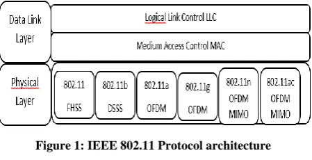
[image:1.595.318.543.405.520.2]The physical layer defines radio wave modulation and signaling characteristics for data transmission, while the data link layer defines the interface between the machine bus and the physical layer, including a near access method of that used in the Ethernet standard and the communication rules between the different stations [13]. The 802.11 standard therefore actually proposes three layers (a physical layer called PHY and two sublayers relative to the data link layer of the OSI model), defining alternative transmission modes that can be represented in the following way:
Figure 1: IEEE 802.11 Protocol architecture
2.2
IEEE 802.11 Topology
The IEEE 802.11 standard defines two deployment modes: Infrastructure mode and no infrastructure mode (ad hoc).
The Infrastructure mode:
The infrastructure network requires the use of access points that manage all communications in the same geographical area in the form of a cell. Each cell called BSS (Basic Service Set) is controlled by a base station (AP) [2].
In order to extend the coverage area, multiple BSSs are used with access points that are connected by a central wired network called the distribution system (DS). The set of interconnected BSSs and their distribution system form a network which is called ESS (Extended Service Set) [11].
The Ad hoc mode:
2.3
IEEE 802.11 MAC Protocol
This section provides a description of the IEEE 802.11 MAC Protocol, Problem with the 802.11 Standard and IEEE 802.11e MAC protocols.
The IEEE 802.11 standards MAC supports two data packet transmission modes. The Distributed Coordination Function DCF whose implementation is mandatory for all IEEE 802.11 devices running in or out of infrastructure mode. The Point Coordination Function PCF used only in mode with infrastructure, offers an optional synchronous service [4].
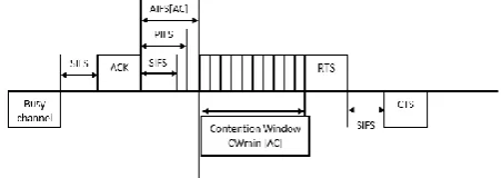
DCF is based on Carrier Sense Multiple Access / Collision Avoidance (CSMA/CA), it abandons collision detection while strengthening mechanisms to avoid it [4]. Each node competes with the other ones for access to the medium. The collisions are avoided by a random backoff procedure which ensures different waiting transmission times to the stations. For the signaling of the good reception of a frame, a mechanism of positive acknowledgment is deployed. Each time a frame is correctly received, an acknowledgment packet must be send to the source. The absence of this acknowledgment indicates a problem in the transmission of the frame. The frame must be retransmitted. This transmission takes place during the CP (Contention Period) [3]. The medium access is managed only by means of a random procedure, that’s why DCF does not provide QoS support but supplies only best effort service. Figure 2
[image:2.595.55.278.453.538.2]PCF is used only in a configuration of an infrastructure network. The method used is the principle of pooling which allows only the stations polled to transmit during the Contention Free Period CFP [3]. The AP waits for an interval called the PCF Inter frame space (PIFS), if the station has nothing to transmit, then the AP goes to the next station. This avoids the problem of collisions encountered in the DCF method.
Figure 2: IEEE 802.11 DCF Channel Access
The MAC in the original 802.11 standard does not provide necessary mechanisms to support the QoS or for identifying and prioritizing different types of flows, so they are not able to reserve guaranteed resources for specific flows. For this reason, IEEE has started another initiative to improve the wireless layer and provide the necessary mechanisms for the correct support of QoS at the MAC layer. These improvements are presented by the 802.11e standard.
2.4
802.11e MAC Protocol
The IEEE 802.11e standard provides quality of service (QoS) improvements at the MAC layer by introducing a service differentiation mechanism which allows priority levels to be set for different network streams.
802.11e introduces the hybrid coordination function (HCF) for QoS support, it defines two medium access mechanisms EDCA (Enhanced Distribution Channel Access) and HCCA (HCF Controlled Channel Access), and those mechanisms were designed to improve existing functions DCF and PCF,
which are based on the same medium access method. The standard 802.11 allows the coexistence of DCF and PCF with EDCA and HCCA to ensure compatibility with existing devices [10].
EDCA:
This method is an evolution of the DCF method. It integrates the differentiation of flow networks, by classifying it into 4 types of traffics (Voice, Video, Best Effort and Background). The MSDUs are delivered to the station by parallel backoff entities, these backoffs are prioritized by using AC-specific contention parameters called EDCA parameter set. There are four Access Categories AC, thus, in every 802.11e station exist four backoff entities. The ACs are labeled according to their application, i.e., AC_VO (voice), AC_VI (video), AC_BE (best effort), and AC_BK (background). The EDCA parameter set defines the priorities in medium access by setting individual interframe spaces IFS, contention windows CW, and other parameters per AC as explained below: The minimum value of the contention window CWmin [AC] is different for each AC, so a small value allows a higher priority class to get more TXOP than a lower priority class [4].
The maximum value of the contention window CWmax [AC] is similar to CWmin, it is defined for each AC according to its priority [4].
Arbitrary Inter Frame Space AIFS [AC]: Each AC uses the backoff procedure once the channel is free for a period equal to AIFS [AC] rather than DIFS. The value of the AIFS [AC] is calculated as follows:
𝐴𝐼𝐹𝑆 𝐴𝐶 = 𝑆𝐼𝐹𝑆 + 𝐴𝐼𝐹𝑆𝑁 𝐴𝐶 × 𝑆𝑙𝑜𝑡𝑇𝑖𝑚𝑒
The value of the AIFSN [AC] is equal to or greater than 2.
TXOPlimit [AC]: After a station has won a TXOP, it is allowed to consecutively transmit a number of packets (burst of packets) belonging to the same AC. The waiting time between receiving an ACK for a packet i and sending the packet i + 1 is SIFS. The TXOPlimit parameter in this case specifies the limit of the number of packets to be transmitted in this burst. It should be noted that this parameter is optional in EDCA, and if it is not activated, then each station is allowed to transmit a single packet at a time [4].
Figure 3: IEEE 802.11e EDCA Channel Access HCCA:
[image:2.595.316.542.545.625.2]through a control or management frame package. This packet must be sent for each stream.
Although the HC designates QSTA to emit using flux characteristics, HCCA TXOPs are assigned for QSTA rather than for flus. Therefore, it is up to the QSTA to allocate that HCCA TXOP to one of its streams [3].
2.5
IEEE 802.11n
The IEEE 802.11n standard, can reach a high throughput using the MIMO (multiple-input multiple-output) technology on each of the usable frequency bands, unlike the 802.11 Legacy which uses SISO (single-input single-output) [9], it can also maintain the coexistence between the various standards (a,b,g,e). More details about 802.11n standard are given by [5].
In this paper we are interested in the performance evaluation of the 802.11n and 802.11e standards. Indeed, the first one currently represents the most marketed Wi-Fi cards, while the second represents the standard with an implementation of service quality. We are content to give a review of these two standards. Further details about other standards are given by [5], [14].
3.
HANDOVER IN IEEE 802.11
STANDARD
Roaming, or handover, or even called Wi-Fi roaming, is the action that a station must take to change its access point (AP) without losing its network connectivity [8].
The standard defines some rules allowing the stations to choose the AP to which they want to associate: [7].
When the terminals move, they must remain synchronized in order to communicate. To maintain synchronization, the access point periodically sends tagged frames called Beacon Frames, which contain the value of the access point clock. Upon receiving these frames, the stations update their clocks to remain synchronized with the access point [12].
When a terminal wants to access a BSS or an ESS controlled by one or more access points, it chooses an access point to which it associates according to a certain number of criteria: Signal strength, Packet error rate and Network load [1]. If the transmission power of the access point is too low, the station searches for another suitable access point in two ways: passive or active [1].
In the passive listening, the station waits to receive a beacon frame from the access point. However, for the active listening, once the station has found the most appropriate access point, it sends it an association request directly via a Probe Request Frame and waits for the AP to respond to associate with it. When the terminal is accepted by the access point, it is authenticated by the new AP using open authentication, WEP, WPA or WPA2. This authentication is followed by a re-association between the MN and the new AP. Re-re-association is the last step to finalize the communication transfer [1]. Periodically, the terminal monitors all channels on the network to evaluate if another AP has better performance. When a station changes its original access point it is either because it has detected a decrease in signal strength or the network traffic is too high on the original access point [1].
4.
NETWORK TOPOLOGY PLANNING
The aim of this study is to provide an expended internet coverage for all university students, based on Wi-Fi technology all along a hall which length is 2km.
The planning specifications imposes a continuity of connection while optimizing the number of access points used, which means that the arrangement of the access points must be done in a way that keeps them juxtaposed to ensure a minimum overlap.
Regarding the standard used, we have worked with the 802.11n because it offers a better throughput and a better transmission performance, and also because the majority of devices communicating through this network implement this standard. The access points that have to be chosen must have the following characteristics:
Frequency = 2400 Hz Data Rate = 54 Mbps Transmit power = 0.001 W
Pr: Packet Reception-Power Threshold = -85 dbm Ge: Gain Emission
Gr: Gain Reception
Based on the above parameters and to determine the maximum coverage of the access point, we use the following equation:
Pr = 𝑃𝑡 − (32,4 + 20 log 𝑓 + 20 log 𝑑) + 𝐺𝑒 + 𝐺𝑟
𝑃 𝑑𝑏𝑚 = 10 log 𝑃 𝑚𝑤
The access point diameter is: D = 345 m, and the radius is: R = 172.5 m.
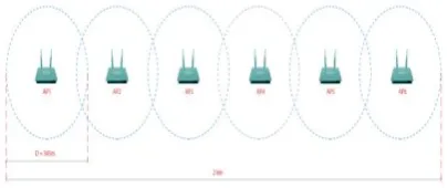
[image:3.595.330.533.490.575.2]Combining the previous results, we deduce that 6 AP is needed to cover a length of 2 km as shown in the figure below:
Figure 4: Planning of the network using 6 access points with a diameter of 345M
5.
PERFORMANCE EVALUATION
We use OPNET 17.5 to evaluate the performance of the proposed network, based on a study that confirms that OPNET is among the best performing and most used simulators.
Table 1: Characteristic of the traffics used
Frame Size (bytes)
Type of service
Data 5000 Best Effort
Multimedia 17 280 Interactive
Multimedia
The server used is both a DATA and a Multimedia server, it is used to simulate an internet connectivity.
[image:4.595.316.545.164.263.2]The access points have the same physical configuration mentioned in table 2 except the BSS identifier which changes from one access point to another:
Table 2: Access Point physical configuration
Standard Frequency Data Rate
802.11n 2400 Hz 54 Mbps
Fixed and mobile clients are connected to the first BSS, BSS Identifier = 1.
In the case of mobility, we define 3 trajectories whose characteristic are presented by the following table
Table 3: Characteristic of the trajectories used
Speed Duration
Low speed 1 m/s 33 min
Average speed 5 m/s 8 min
High speed 10 m/s 4 min
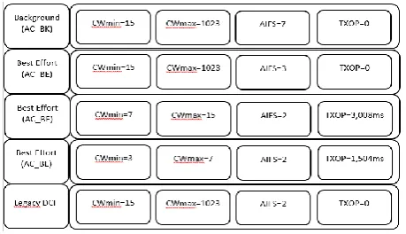
In each scenario we use either the method of access DCF or EDCA, the values used are by default described below in Figure 5.
Figure 5: Default EDCA and DCF Legacy parameters
5.1
Topology
5.1.1
Fixed case
[image:4.595.317.546.415.510.2]In this first fixed topology, two types of traffic are used, Data (best effort) and Multimedia. We will compare the variation of delay and packets loss rate in the three cases: 1, 5 and 10 fixed clients. The comparison will be done for DCF and EDCA, which generates 4 scenarios for each case.
Figure 6: Example of the three cases of the fixed topology 1 client: Low Traffic Load
For this first case, the Multimedia delay value is significant and even higher than Data delay in the DCF access method, because this method uses a random mechanism, the two streams are then in legal competition to access the channel. On the other hand, the EDCA access method offers a better Multimedia delay because it prioritizes the Multimedia stream.
The loss rate is zero in the 4 scenarios, because the network is not yet congested. Figure 7
Figure 7: Comparison of the DCF and HCF Delay and Loss Rate for Multimedia and Data traffic in the case of 1
client 5 clients: Medium Traffic load
In this second case, Figure 10 illustrates the delays of the Multimedia and Data traffic are significantly enhanced due to the use of the HCF compared to the DCF. It shows also that the loss rate is always null for the 4 scenarios.
Figure 8: Comparison of the DCF and HCF Delay and Loss Rate for Multimedia and Data traffic in the case of 5
[image:4.595.54.284.562.694.2] [image:4.595.316.544.611.702.2]10 clients: High Traffic load
In the third case, the loss rate has increased compared to the previous scenarios, which is logical because the network becomes congested and the access point has a limited queue size which once saturated, it starts to drop packets.
With the use of the HCF the loss rate has significantly been reduced, compared to the case of the DCF.
[image:5.595.318.544.71.166.2]The loss rate affects the delay and for this reason the delay of the Multimedia in the case of the DCF is better than that using the HCF.
Figure 9: Comparison of the DCF and HCF Delay and Loss Rate for Multimedia and Data traffic in the case of
10 clients
5.1.2
Mobile case
In this second topology, the two types of traffics: Data (Best Effort) and Multimedia, are considered. We compare the delay variation and packet loss rate using DCF and HCF for 1, 5 and 10 mobile clients in the case of a speed of 1 m/s, 5 m/s and 10 m/s.
F
igure 10: Example of the three cases of the mobile topology1 client: Low Traffic load
[image:5.595.56.284.194.286.2]The use of the HCF reduces delay values compared to the DCF for both types of traffics, and for different speeds. The loss rate of Multimedia traffic manifest lower values in the HCF than in the case of the DCF, and it is almost null for Data traffic in both DCF and HCF cases.
Figure 11: Comparison of the DCF and HCF Delay and Loss Rate for Multimedia traffic in the case of 1 MOBILE
[image:5.595.317.544.274.481.2]client
Figure 12: Comparison of the DCF and HCF Delay and Loss Rate for Data traffic in the case of 1 MOBILE client
5 clients: Medium Traffic load
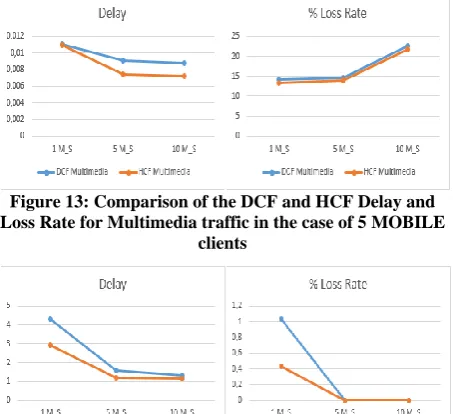
[image:5.595.55.284.396.520.2]For the case of 5 clients, same results as in the case of a single client are obtained. The HCF gives better results for the 4 scenarios: Figure 13 and 14.
Figure 13: Comparison of the DCF and HCF Delay and Loss Rate for Multimedia traffic in the case of 5 MOBILE
clients
Figure 14: Comparison of the DCF and HCF Delay and Loss Rate for Data traffic in the case of 5 MOBILE clients 10 clients: High Traffic load
In the case of high traffic, the delay values obtained for the multimedia traffic using the DCF is minimal than the HCF, this can be explained by the fact that the DCF manifests a high loss rate which directly impacts the delay (low delay values). Figure 22, 24
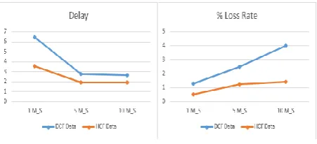
For Data, the delay and loss rate using HCF is better than the DCF. Figure 23, 25.
Figure 15: Comparison of the DCF and HCF Delay and Loss Rate for Multimedia traffic in the case of 10
[image:5.595.56.283.619.711.2] [image:5.595.316.544.633.728.2]Figure 16: Comparison of the DCF and HCF Delay and Loss Rate for DATA traffic in the case of 10 MOBILE
clients
6.
CONCLUSION
In this works, we have planned a physical deployment of wifi technology to cover a part of the university campus. We have considered physical characteristics of the communicating devices and also the access point, to enable a continuous connectivity while optimizing the number of the AP. At Mac layer, and in order to offer an acceptable QoS level, for different types of traffic (especially multimedia), we propose to use the 802.11e, to enhance the Quality of the service offered by the network. We proved that such investment is really worthy, in the measure where it gives better performance than the use of 802.11n alone, even with the presence of mobile users.
In the future the plan is to study and evaluate mobility performance in the case of macro mobility using the protocol Mobile IP.
7.
REFERENCES
[1] Kashif Nizam Khan, Jinat Rehana, “Wireless Handoff Optimization: A Comparison of IEEE 802.11r and HOKEY” Springer, vol. 6164, 2010, pp. 118–131. [2] Adlen Ksentini, “Quality of service (QoS) in IEEE
802.11-based Wireless Local Area Networks (WLAN),” Cergy-Pontoise University, 2005.
[3] G. Cecchetti and A. L. Ruscelli, “Real-time support for HCCA function in IEEE 802.11e networks: a performance evaluation,” Security and Communication Networks, vol. 4, no. 3, Mar. 2011, pp. 299–315.
[4] Dr. Jyotsna Sengupta and Er. Gurpreet Singh Grewal, “Performance evaluation of IEEE 802.11 MAC layer in supporting delay sensitive services,” International Journal of Wireless and Mobile Network, vol. 2, no. 1, Feb. 2010, pp. 42–53.
[5] Eldad Perahia and Robert Stacey, Next Generation Wireless LANs, Throughput, Robustness and Reliability in 802.11n. Cambridge University: Cambridge University Press, 2008.
[6] D. Gao, J. Cai, and K. N. Ngan, “Admission control in IEEE 802.11 e wireless LANs,” IEEE network, vol. 19, no. 4, 2005, pp. 6–13.
[7] Y. Grunenberger and F. Rousseau, “Virtual access points for transparent mobility in wireless LANs,” Wireless Communications and Networking Conference (WCNC), 2010, pp. 1–6.
[8] Kevin Denis, “Le roaming en wifi.” Jun-2007.
[9] C.-Y. Wang and H.-Y. Wei, “IEEE 802.11n MAC Enhancement and Performance Evaluation,” Mobile Networks and Applications, vol. 14, no. 6, Dec. 2009, pp. 760–771.
[10]Z. Wan, N. Xiong, N. Ghani, A. V. Vasilakos, and L. Zhou, “Adaptive unequal protection for wireless video transmission over IEEE 802.11e networks,” Multimedia Tools and Applications, vol. 72, no. 1, Sep. 2014, pp. 541–571.
[11]LAHFA FEDOUA, “Quality of Service in IEEE 802.11 Wireless Local Area Networks,” Université Abou Bekr Belkaid, 2010.
[12]“Cours 802.11,” Scribd. [Online]. Available: https://fr.scribd.com/document/180609650/Cours802-11. [Accessed: 20-Sep-2017].
[13]“IEEE 802.11 Standards - Deploying Secure 802.11 Wireless Networks with Microsoft Windows.” [Online]. Available: http://flylib.com/books/en/2.219.1.9/1/. [Accessed: 25-Sep-2017].
[14]“IEEE 802.11,” Wikipedia. 26-Sep-2017