ALEX KING,
School of Computing and Communications, Lancaster University, UKUTZ ROEDIG,
School of Computing and Communications, Lancaster University, UKClear Channel Assessment (CCA) is a core element of Wireless Sensor Network (WSN) Medium Access Control (MAC) protocols which is used on transmitter and receiver side. Current CCA implementations cannot determine the device type occupying the media, leaving nodes unable to differentiate between WSN traffic and interference. However, this would be valuable as MAC protocols benefit from reacting differently depending on the channel occupier. In this paper we describe a method called Power Differentiating Clear Channel Assessment (P-DCCA). Transmitters vary the output power of the radio while the packet is being sent. Receivers are able to identify signals with this characteristic, enabling a Differentiating Clear Channel Assessment (DCCA) check to reveal if the medium is currently occupied by WSN traffic or other interference. We present an implementation and thorough evaluation of P-DCCA. Using ContikiMAC as example we describe how P-DCCA can be integrated within MAC protocols. We show via large-scale testbed experiments and deployments that P-DCCA enabled networks have a significant improved performance. For example, we show that a P-DCCA enabled network can improve Packet Reception Rate (PRR) by up to a factor of 10 while reducing energy usage by over 80% under heavy interference.
CCS Concepts: •Computer systems organization→Sensor networks;
Additional Key Words and Phrases: Medium Access Control, Radio Interference, Network Coexistence
ACM Reference Format:
Alex King and Utz Roedig. 2018. Differentiating Clear Channel Assessment using Transmit Power Variation.
ACM Trans. Sensor Netw.1, 1, Article 1 (January 2018),28pages.https://doi.org/0000001.0000001
1 INTRODUCTION
Wireless Sensor Networks (WSNs) are often deployed in environments where they have to coexist with other networks. For example, it is common to find 802.15.4 based WSNs sharing the transmis-sion medium with 802.11 type WiFi. The state of the communication medium (busy or idle) is used to determine WSN node behaviour. Before transmitting, nodes use this information to decide if a packet can be transmitted or if the communication attempt should be deferred (back-off). On the receiving side nodes use this information to determine if the radio should remain in a power efficient sleep state, or be awoken to receive an incoming packet. Transceiver chips implement a Clear Channel Assessment (CCA) which allows nodes to sample briefly the channel and to determine its state. The available CCA method of currently used 802.15.4 transceiver chips only indicates if the channel is busy or idle; it is not possible to determine the network type currently occupying the channel.
However, in many situations such information would be beneficial as node behaviour could then be tuned more aptly, to improve network performance and energy efficiency. Transmitters may employ different back-off strategies depending on the node type currently occupying the channel. For example, knowing that a comparatively short WiFi transmission is occupying the channel, a
Authors’ addresses: Alex King, School of Computing and Communications, Lancaster University, Lancaster University, Lancaster, LA1 4WA, UK; Utz Roedig, School of Computing and Communications, Lancaster University, Lancaster University, Lancaster, LA1 4WA, UK, [email protected].
sensor node may back-off for a much shorter duration than it would when detecting an 802.15.4 transmission. Receivers may decide on different sleep patterns depending on the current channel occupation, such as not extending the node wake cycle if the occupying transmitter is not part of the 802.15.4 WSN.
Implementing CCA capable of interference differentiation on current WSN hardware is extremely challenging due to the limitations of the low power radio, such as the commonly used TI CC2420 and its newer derivates. Previous works on interference classification have proven that high accuracy is achievable on limited resources. However, these existing works operate on timescales far exceeding the standard CCA duration, precluding a like-for-like replacement.
In this paper we overcome this limitation and describe a novel method for Differentiating Clear Channel Assessment (DCCA) compatible with current off-the-shelf transceiver hardware such as the TI CC2420. Transmitters in an 802.15.4 WSN network vary the transmission power during packet transmission. Receivers can then identify this encoded information during a brief CCA check, allowing nodes to determine if the channel is currently occupied by a node belonging to the same WSN network or not. We refer to this CCA implementation as Power Differentiating Clear Channel Assessment (P-DCCA). The focus of our work presented in this paper is on the core P-DCCA mechanism. We do not aim to detail in this work optimal policies for particular MAC protocols using P-DCCA. However, we show using ContikiMAC [9] that even the implementation of very simple policies based on P-DCCA lead to tremendous performance improvements.
This paper provides the following contributions:
• P-DCCA – DCCA based on transmit power variation:A novel method for Differentiating Clear Channel Assessment (DCCA) based on variations in transmission power output is described. A P-DCCA check reveals if the transmission medium is occupied by another WSN node or if external interference is occupying the channel.
• P-DCCA evaluation:A detailed evaluation of P-DCCA is given. Specifically, we evaluate detection accuracy, cost in terms of energy consumption and the impact on transmission range. We show that a channel occupier can be identified correctly in 88% of cases for 802.15.4, 94% of cases for other interference, and that P-DCCA requires little more energy than a normal CCA check. We also quantify the impact of power variation on achievable communication range (30% range reduction in a typical setting). We compare P-DCCA with the closest related mechanism ZiSense – although it cannot be considered as like-for-like replacement – and show that it outperforms this existing alternative.
• P-DCCA application:We showcase P-DCCA as part of ContikiMAC, and evaluate in settings where the network must coexist with WiFi devices. Our evaluation, which includes a 49-node testbed experiment, shows that P-DCCA significantly improves packet reception (up to ten-fold increase) and energy usage (over 80% reduction), under heavy interference.
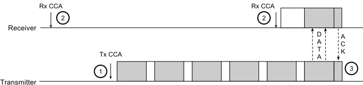
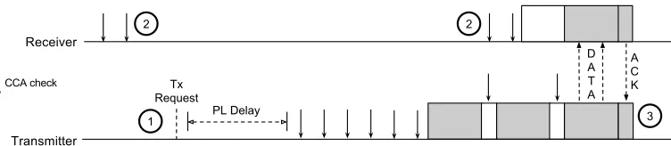
Fig. 1. Operation of LPL MAC protocols: 1) Transmit request followed by CCA check, then packet strobes. 2) Periodic receiver CCA check to listen for incoming packets. 3) After data is received, an ACK is transmitted, packet strobes stop.
2 PRELIMINARY DISCUSSION
The 802.15.4 physical layer is a common choice for WSNs due to its low power consumption and suitability for low data rate applications. The 2.4 GHz frequency is shared with other protocols and devices; as their prevalence continues to increase, parallel deployments with 802.15.4 are becoming more common. Without due consideration to network coexistence, network performance is sub-optimal. Sources of interference include Bluetooth, WiFi, and other 802.15.4 devices, as well as non-communication devices such as microwave ovens.
2.1 CCA and the Case for DCCA
WSN MAC protocols use CCA on the transmitter and receiver side. As CCA only allows us to distinguish a busy from an idle channel the same policy must be used for all channel busy cases. However, a less ambiguous CCA response would be advantageous, allowing nodes to implement a response dependent on the nature of the interference.
Transmitter CCA.802.15.4 nodes must assess the state of the channel before transmitting data to avoid collisions with other nodes and to increase the likelihood of the data being received (see Figure 1). For example, a sender will defer and retry later upon detecting other channel activity - presumed likely to corrupt any transmission attempt. CCA checks are commonly used for this purpose: briefly sampling the channel and indicating the current state. Currently used CCA implementations offer an energy threshold indicator: busy if the energy on the channel exceeds a set threshold, free otherwise. As noise can lead to a false channel assessment, CCA methods have been devised which analyse a number of consecutive CCA checks together [21]. Such outlier detection improves channel assessment but it can still only be decided if the channel is free or not. This ambiguity requires MAC protocols to implement a single policy in response to all interference. However, to improve network performance senders can opt to ignore interference from sources outside the network, as the recipient may still be able to receive the packet over the interference. This response is reasonable in cases without mutual channel etiquette, such as WiFi. Alternatively, the transmitter can apply different back-off timing depending on the interference source. When competing with WiFi nodes for a channel, much shorter back-off timers are required than in a case where competing with other 802.15.4 nodes. The optimal response policy depends on the MAC protocol used, the coexisting network(s) and the traffic patterns in the network.
in an energy efficient sleep state, retaining operational information (such as channel, transmission power), but unable to send or receive packets. In order to receive data, nodes must periodically listen to the channel for incoming transmissions, a period defined by theduty cycle. A node wishing to send data to another node must transmit repeatedly to the recipient throughout this duty cycle, terminating only if an acknowledgement has been received, or a timeout has occurred.
Due to the small energy cost and immediate response, CCA is commonly used to sample the channel, quickly indicating the channel state. Detecting an occupied channel, the radio is left powered on to receive any subsequent packet, otherwise returning the radio to a sleep state.
Once again, the ambiguity of CCA requires nodes to implement a single policy in response to any channel activity. In environments frequented by other interference, this leads to increased
false wake-ups, where nodes listen to the channel in response to spurious interference, wasting energy. To improve energy consumption a node can implement different policies in regard to the interference type detected. It is sensible to prevent a wake-up in case of non-802.15.4 traffic.
2.2 DCCA Options
As shown, DCCA is a valuable building block for MAC protocols and the question is how it can be realised. We consider three possible avenues to realise DCCA: Modulation Detection Differentiating Clear Channel Assessment (MD-DCCA), Time Differentiating Clear Channel Assessment (T-DCCA), and P-DCCA.
Modulation Detection Differentiating Clear Channel Assessment (MD-DCCA).The 802.15.4 stan-dard defines modulation detection as an optional CCA method - indicating busy if a signal with the correct modulation and spreading characteristics is detected. Alongside energy detection, this would be ideal for implementing DCCA with little processing overhead. This approach, termed MD-DCCA, could discern between a free channel, a non-802.15.4 interferer (such as WiFi), and 802.15.4 transmissions, thereby achieving DCCA. Unfortunately, in order for transceivers to provide modulation detection, more complex radio circuitry is required. Therefore, most currently available transceivers do not implement this method, and opt instead only for simple energy detection CCA. This is the case with the Texas Instruments family of IEEE 802.15.4 transceivers, including the CC2420, found in many WSN installations. While the specification for the CC2420 [13] suggests that all CCA modes are supported, this is not the case for modulation detection, where a busy channel is inferred only if a packet is currently being received. Since this requires being able to receive and decode the packet preamble, this is insufficient to implement DCCA.
This was confirmed experimentally using three Tmote Sky nodes. The first was programmed to transmit packets continuously. The other two nodes continuously performed CCA, one using energy detection and one using modulation detection. Two experimental runs were carried out. In the first, sender and receivers use the same Start Frame Delimiter (SFD) while in the second run different SFD are used.
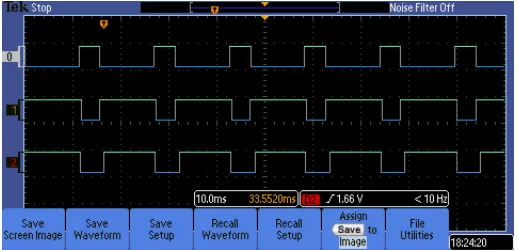
The results are shown in Figure2. Channel 0 shows the transmitter, a high signal is shown when a packet is in transmission. Channel 1 shows the receiver using modulation detection and Channel 2 shows the receiver with energy detection. The receivers show a low signal when the CCA detects a transmission. Figure2(a) shows the results when sender and receiver use the same SFD setting while Figure2(b) shows the result for differing SFD configuration.
(a) CC2420 CCA with same transmitter and receiver SFD.
[image:5.486.114.373.89.214.2](b) CC2420 CCA with different transmitter and receiver SFD.
Fig. 2. CC2420 CCA implementations using energy and modulation detection modes. If the value of the SFD at the receiver is changed, modulation detection can no longer detect IEEE 802.15.4 packets
available on the TI CC2420 family. The same observation has been made previously by Petrova et al. [20].
Time Differentiating Clear Channel Assessment (T-DCCA).The different observable characteristics between Physical Layer (PHY) and MAC layers can be leveraged to implement DCCA. For example, the largest 802.11g packet requires only 254µs on-air time, while the largest 802.15.4 packet requires 4224µs. Likewise, the Orthogonal Frequency Division Multiplexing (OFDM) used by 802.11n means that the energy on a single overlapping 802.15.4 channel varies throughout the transmission. This is unlike 802.15.4 modulation, which uses Direct Sequence Spread Spectrum (DSSS) and has a more static profile.
WSN nodes can observe these features by recording a Received Signal Strength Indicator (RSSI) trace at high frequency, from which 802.15.4 signals can be identified in the time domain. Hence, this approach is termed T-DCCA. To achieve high accuracy, nodes implementing T-DCCA require a longer listening duration than compared to the standard IEEE 802.15.4 CCA. This increases latency before receivers can react to a DCCA result, and increases the energy consumption of idle listening. ZiSense [28] is an implementation of T-DCCA which we use for comparison with the P-DCCA approach presented in this paper.
to reduce the required sampling duration, P-DCCA does not rely on inherent 802.15.4 features, such as spectral profiles and packet durations. Instead, P-DCCA relies on an additional signal component that is modulated by the transmitter, and can be detected by analysing an RSSI trace. This is orthogonal to the data transmission, and acts only to differentiate signals from interference. Since these features are intentionally observable on a smaller timescale, the detection time is reduced compared to T-DCCA.
One implementation of P-DCCA, which we describe in Section3, achieves this by varying the output power cyclically throughout packet transmission. P-DCCA receivers sample the RSSI register at high frequency, detecting these encoded characteristics within the trace. Signals which lack this feature are assumed to be other interference. This approach has a short detection period, close to the IEEE 802.15.4-standard CCA duration, and thus has a lower idle listening cost compared to T-DCCA.
2.3 Discussion
Traditional energy-based CCA has limitations and we have presented DCCA as a conceptual extension to CCA. DCCA enables us to differentiate interference sources and to implement policies on handling interference.
MD-DCCA would be an efficient solution, however, as this mechanism is not available on most radio chips used today it is desirable to have alternative methods at hand. Both T-DCCA and P-DCCA rely on RSSI features, recorded over time, to identify interference. The former is a passive approach, and relies on features inherent to the IEEE 802.15.4 PHY, and MAC protocol, and therefore requires long sampling durations which reduce energy efficiency. Conversely, P-DCCA is an active approach, which modulates an orthogonal signal feature to all outgoing transmissions. This can be detected during far shorter P-DCCA checks - hence improving energy efficiency. Also, this method allows us to differentiate between two different 802.15.4 networks if required.
The power variation used in P-DCCA reduces the Signal to Noise Ratio (SNR) of the transmission, which in turn reduces the maximum communication distance (See evaluation in Section6). This presents a tradeoff between P-DCCA and T-DCCA in terms of shorter idle listening and link range.
3 Power Differentiating Clear Channel Assessment (P-DCCA)
In this section, P-DCCA is described in detail, including an implementation on WSN hardware. Our approach is based on varying the output power between two values during packet transmission. Our implementation is based on the common TI CC2420 transceiver, however we believe P-DCCA should be implementable on any IEEE 802.15.4-compliant hardware. An implementation of T-DCCA based on ZiSense [28] is also briefly described. We use this implementation in our evaluation to compare our P-DCCA approach with T-DCCA.
3.1 P-DCCA Mechanism
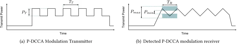
P-DCCA requires transmission of packets with alternating transmission power. A P-DCCA check must detect this information if present. Within this process the implementation specifics of the RSSI measurement facility on transceiver hardware must be taken into account. The 802.15.4 specification states that CCA detection time shall be equal to eight symbol periods. Hence, a reading of the RSSI register on currently available 802.15.4 transceivers provides an average RSSI measurement over eight symbol periods. Alteration of the transmission power as used for P-DCCA and as shown in Figure3(a)is perceived as slow increase or decrease of the RSSI at the receiver as an average is computed (see Figure3(b)).
(a) P-DCCA Modulation Transmitter (b) Detected P-DCCA modulation receiver
Fig. 3. P-DCCA transmitter power cycle and observed RSSI reading at a receiver node.
Table 1. P-DCCA parameters and values for CC2420 802.15.4 Transceiver.
Parameter Description CC2420
PT Difference between the two used power levels 5dB
TT Transmit power variation period 256µs
TR Duration of a P-DCCA check 256µs
NR Number of RSSI samples taken during a P-DCCA check 8
C Duration of a RSSI sample 32µs
Pmin Minimum power range of the P-DCCA sample set 2dB Pmax Maximum power range of the P-DCCA sample set 7dB Pδ Maximum power difference between two consecutive P-DCCA samples 4dB
NE Maximum number of extrema in the P-DCCA sample set 2
τRSSI The minimum threshold for each RSSI sample -75dB
procedures in detail. Parameters governing these mechanisms are given in Table1. Table1also shows settings for these parameters as used within our implementation of P-DCCA based on a TI CC2420 transceiver, which we describe later.
3.2 P-DCCA Signal Transmission
PT andTT define the power-cycle of P-DCCA, used during the transmission of P-DCCA modulated packets. Packets are transmitted while alternating between two transmit power settings1resulting in a transmit power range ofPT. Each transmit power is used for the same length of time covering
the periodTT.
TT is set to 256µs. This is twice the length of the RSSI averaging window, which in most cases is
8 symbol periods (128µs). Thus, it is ensured that the maximum and minimum transmission power level used are each fully represented in the RSSI register during a power-cycle (see Figure3(b)). Aligning the power-cycle durationTT with the RSSI averaging time ensures that a node performing P-DCCA can observe a signal constantly alternating between minimum and maximum power which simplifies the detection process.
PT must be large enough to ensure that signal features are reliably discernible to receivers.
PT must be selected such that power variations can be distinguished clearly from natural signal strength variations.PT must also be minimised such that transmission power remains sufficiently strong at the intended receiver, as reduced transmit power leads to a reduced transmission range.
1In practical settings the strongest and second strongest available transmission power are used but other power settings are
3.3 P-DCCA Signal Detection
A simple algorithm is necessary for signal analysis as a fast execution on resource constraint nodes is necessary. The signal analysis must be carried out during a brief CCA check. The wave form as shown in Figure3(b)must be detected reliably. This can be achieved by simply detecting local power extrema and analysis of power ranges. During P-DCCA the RSSI register is sampled periodically for a period of timeTR. The sampling period must be larger or equal to the power-cycle periodTT
to ensure that at least one complete set of power extrema is covered (TT ≤TR). The collected RSSI
sample setis then analysed using Algorithm1.
Algorithm 1Power Differentiating Clear Channel Assessment (P-DCCA).
1: fori = 1toNRdo
2: if(s[i] = RSSI())<τRSSI then break 3: ifi=1then returnCLEAR
4: ifi<NRthen returnBUSY_INCONCLUSIVE 5: fori=1to(NR−1)do
6: if|s[i]−s[i+1]|>Pδ then returnBUSY_OTHER 7: ifs[i]>s[i+1]∧slope,SLOPE_I NCREASI NGthen 8: slope ←SLOPE_I NCREASI NG
9: counter ←counter+1
10: ifs[i]<s[i+1]∧slope,SLOPE_DECREASI NGthen 11: slope ←SLOPE_DECREASI NG
12: counter ←counter+1
13: if(ranдe(s) <Pmin∨(ranдe(s) >Pmax)∨(counter>NE))then
14: return BUSY_OTHER
15: return BUSY_PDCCA
The first two lines in the algorithm fill the sample sets with RSSI values until a single value below the thresholdτRSSI is received, or untilNRsamples have been taken.NRis dictated by the
achievable sampling frequency andTR. If the first RSSI sample is below the thresholdτRSSI, P-DCCA
indicates that the channel is free, without taking any more samples. Thus, an unoccupied channel causes P-DCCA to behave identically to the normal CCA method. IfNRsamples are collected over
the minimum threshold, the algorithm measures these samples against the given thresholds in Table1. On line 6, the absolute value between consecutive samples is compared againstPδ, and
lines 7 through 12 count the number of local power extrema. Finally on line 13, the range of the samples and the number of local extrema are compared against their thresholdsPmin,PmaxandNE
respectively. A signal passing these thresholds is classified as a valid, P-DCCA modulated 802.15.4 signal.
3.4 P-DCCA Outcome
P-DCCA can have four distinct outcomes:
(1)CLEAR: indicates that the medium is currently free.
(2)BUSY_PDCCA: indicates that a transmission with P-DCCA power modulation was detected. (3)BUSY_OTHER: indicates that another signal without P-DCCA was detected, such as WiFi,
Bluetooth, or another IEEE 802.15.4 device outside the network.
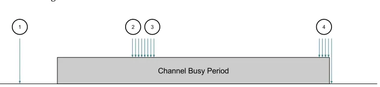
Fig. 4. Possible P-DCCA outcomes: 1) One sample: channel is clear (CLEAR) 2) Complete sample set: channel is eitherBUSY_PDCCAorBUSY_OTHER3) Incomplete sample set: channel is busy, but unknown origin:
BUSY_INCONCLUSIVE
P-DCCA requiresNR RSSI samples, above the threshold, to identify a signal. Therefore, if a P-DCCA check coincides with the end of a busy period, an incomplete RSSI set may be recorded and no source may be definitively identified. This results in aBUSY_INCONCLUSIVEresult, the interpretation of which is left to the MAC layer. Situations leading to these P-DCCA outcomes are shown in Figure4.
3.5 P-DCCA Interpretation
Node behaviour after obtaining a P-DCCA result is to be decided by upper layers.CLEARmay be treated similar to a clear resulting from a normal CCA.BUSY_PDCCAwould trigger the back-off procedures designed to coordinate competition for the channel among nodes of the same network. The reaction toBUSY_OTHERmay depend on knowledge of the deployment area. For example, it might be known that other interference is likely to stem from a co-located WiFi network.
In case ofBUSY_INCONCLUSIVEthe decision may depend on worst-case or best-case assumptions. For example, a prudent node listening to the channel for incoming packets may treat this result as normal 802.15.4 traffic, leaving the radio powered on to receive data, while an energy-conscious node may ignore altogether any interference except confirmed 802.15.4 traffic.
Alternatively,BUSY_INCONCLUSIVEresults can be avoided altogether by stipulating design requirements on the MAC protocol. Knowing the duration between packet transmissions, two P-DCCA checks can be arranged so that at least one will fall within a packet transmission. Thus, inconclusive results can be ignored entirely. This approach ensures that at least one sample set captures a P-DCCA signal, ensuring reliable operation.
3.6 CC2420 Implementation of P-DCCA
Our implementation and evaluation of P-DCCA is based on the Tmote Sky WSN platform [6]. This platform uses the TI MSP430 MCU and CC2420 radio, which is compliant with the IEEE 802.15.4 PHY. The specific P-DCCA parameters used for the implementation are given in Table1.
The RSSI register of the CC2420 does not contain an instantaneous representation of the current channel energy. It contains an average over the preceding 8 symbol periods of 128µsduration. We setTT =256µs. We setTR=TT as we decided to use only one power-cycle for detection (NE =2). LargerTRcould improve detection accuracy but would increase P-DCCA duration which would have an additional energy cost. However, as our evaluation shows (see Section4) this duration is sufficient to achieve high detection accuracy. We use a power difference ofPT = 5dBas we observed this to be the smallest power difference yielding good detection accuracy. The transmit power alters between 0dBand−5dB.
with every second IEEE 802.15.4 symbol. Based on this,NR =8 samples are collected during a
power-cycle of lengthTT. We empirically setPmin =2dB,Pmax =7dBandPδ =4dBwhich is
tuned to the chosen transmission power differencePT =5dBand accuracy of the CC2420 RSSI
measurement facility.
P-DCCA is implemented in the Contiki WSN OS [10], where operation of the radio driver strays little from the standard implementation. The function used to transmit a packet blocks until the transmission of a packet has been completed; in P-DCCA, this blocking time is used to modulate the output power. In our measurements, the P-DCCA function call may take up to 260µs, as opposed to the immediate response with normal CCA; this timing component must be accounted for in the implementation of MAC protocols.
3.7 Implementation of T-DCCA
In ZiSense RSSI traces are searched for known IEEE 802.15.4 signatures. ZiSense is designed to improve the wake-up and rendezvous mechanism in WSN MAC protocols: to reduce the false wake-up problem, and improve the resilience of synchronisation packets in protocols such as X-MAC [4]. Although ZiSense was not directly designed as DCCA mechanism, it can be employed in this capacity as representation of T-DCCA and we use it in this work for comparison in our evaluation.
Each ZiSense check listens to the channel for a fixed duration, sampling the RSSI into a buffer. The buffer is analysed and segments are identified as contiguous subsets of RSSI samples when the signal differs from the noise floor. For each segment detected, a feature-set is constructed describing:
(1) On-air time
(2) Peak-to-Average Power Ratio (PAPR) (3) Inter-Packet Spacing (IPS)
(4) Under Noise Floor (UNF)
(1) and (3) describe temporal features of the signal, which are typically specific to the MAC protocol. The original authors of ZiSense used TinyOS LPL as the MAC protocol in their evaluation. (2) stems from the modulation used by the transmitter. (4) is a feature unique to interference from electric machinery (i.e. Microwave Ovens), where the signal strength drops below the noise floor. These feature sets are then passed to a classification algorithm, to classify each segment as either IEEE 802.15.4 or other. In [28], three algorithms are described:ZiSense-1,ZiSense-2, andZiSense-C4.5.
• ZiSense-1: A classifier manually derived from strict interpretation of IEEE 802.15.4 PHY and TinyOS LPL.
• ZiSense-2: A more forgiving classifier manually derived to identify segments that have collided with other interference.
• ZiSense-C4.5: A classifier build using the C4.5 algorithm, which builds a decision tree classifier from a prior-known dataset - in this case from segments which were identified manually. Since no implementation of ZiSense is currently available we recreated the ZiSense algorithm offline, based on [28]. Our implementation samples the RSSI register at the same frequency into a buffer on a Tmote Sky sensor node. Once full, these raw RSSI values are sent to the host computer via serial link. The ZiSense classification algorithms described above are then run offline. An offline approach avoided complications in developing embedded WSN software, while still allowing for classification accuracy comparisons.
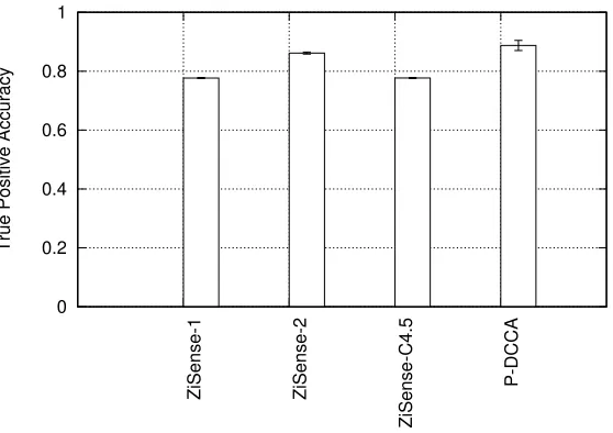
In this section, we evaluate the accuracy of the P-DCCA classification algorithm, and compare it with the ZiSense T-DCCA classification algorithm. We evaluate both DCCA mechanisms in terms of True Positive (TP) and False Positive (FP) rates, these are defined as:
• True Positive (TP) Rate- the rate of correct WSN transmission classification by the DCCA algorithm.
• False Positive (FP) Rate- the rate of incorrect WSN transmission classification by the DCCA algorithm, in the presence of non-WSN interference.
Accuracy is measured by controlling the interference environment, by injecting either WSN traffic (to measure TP rate), or interference (to measure FP rate). This evaluation considers only the classification accuracy of each DCCA implementation, given a complete RSSI sample set. It is not possible for this comparison to include the underlying sampling mechanism, due to differences in the RSSI sampling approaches. Therefore,BUSY_INCONCLUSIVEresults are ignored in P-DCCA. As discussed in section3.4, the MAC layer should be implemented to considerBUSY_INCONCLUSIVE
results accordingly.
4.1 True Positive (TP) Rate
For this experiment, two Tmote Sky nodes are spaced 4mapart in an unused computer laboratory during quiet office hours. One node transmits packets throughout the experiment, while the other tests the DCCA-variant. The ZiSense detection algorithm relies on temporal characteristics inherent to the applied MAC protocol, which in [28] is TinyOS LPL. Therefore, packets are transmitted 2.9ms apart to emulate LPL traffic. For P-DCCA evaluation these packets are transmitted with power variation. The experiment is repeated five times, during which P-DCCA and T-DCCA are tested for five minutes each.
To evaluate T-DCCA, the offline implementation of ZiSense described in Section3.7is used. The duration of a T-DCCA check and its relation to the LPL transmission timing ensures that each T-DCCA check can obtain sufficient data to identify the ongoing WSN transmission.
To evaluate P-DCCA, it is ensured that the P-DCCA check is carried out while a packet trans-mission is ongoing. To achieve this, transmitter and receiver node are synchronised via a cable connection. Thus, T-DCCA and P-DCCA have both the chance to correctly identify an ongoing transmission within the DCCA check. However, it has to be noted that both DCCA checks have very different time scales (2.9mscompared to 256µs).
The results in Figure5show that P-DCCA achieves higher TP rate than all ZiSense classifications. P-DCCA TP rate is 88%, while ZiSense-1, ZiSense-2 and ZiSense-C4.5 have 78%, 86% and 78% respectively. This experiment shows that using P-DCCA, high classification accuracy can be achieved despite a comparably shorter DCCA duration (2.9mscompared to 256µs).
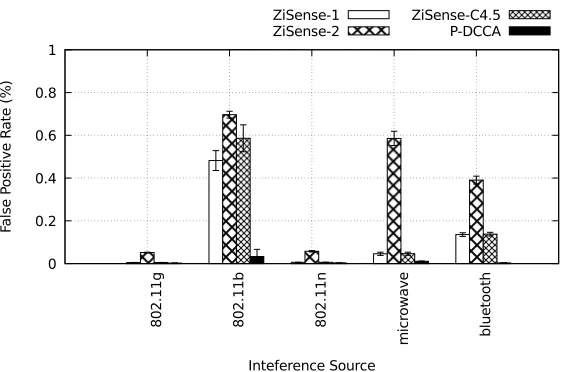
4.2 False Positive (FP) Rate
For this experiment, two Tmote Sky nodes are programmed to act as P-DCCA and T-DCCA receivers, and placed in an unused computer laboratory. The experiment is repeated ten times, each iteration taking five minutes. The experiment takes place during quiet office hours, with minimal external Radio Frequency (RF) activity.
0 0.2 0.4 0.6 0.8 1
ZiSense-1 ZiSense-2
ZiSense-C4.5
P-DCCA
[image:12.486.100.379.89.286.2]True Positive Accuracy
Fig. 5. TP rate of P-DCCA and ZiSense. P-DCCA achieves a better TP rate compared to all ZiSense imple-mentations.
• WiFi: An IEEE 802.11 Access Point (AP) and station are placed at opposite corners of the room. Both are connected to a host computer over a wired connection, which acts as the control channel for the experiment. Interference is generated using the [1] DITG tool, 1000-byte UDP packets are transmitted at a uniform random rate as specified. IEEE 802.11 b, g, and n variants are used in the experiments, as configured by the host computer.
• Bluetooth: Bluetooth traffic is generated by sending a large file between two devices: a MacBook Pro laptop computer and a Google Nexus 5 Android smartphone.
• Microwave oven: Microwave oven interference is generated using a household microwave oven, heating 500ml of water in a pyrex bowl at 800W, replaced at the beginning of each experiment run.
Both nodes continuously call the DCCA function, the outcome of the detection mechanisms is recorded on the host computer. An FP result is recorded whenever an IEEE 802.15.4 packet is detected.
The results are shown in Figure6. For all interference sources, P-DCCA recorded the lowest FP rate. In most cases, this if followed by ZiSense-1 and ZiSense-C4.5. ZiSense-2 records the worst FP rate.
For IEEE 802.11b interference ZiSense variants have a high FP rate. This is due to the closer observable similarity between IEEE 802.15.4 and 802.11b signals: the slower transmit rate and DSSS modulation causes the packet duration and PAPR to fall within ZiSense thresholds. IEEE 802.11g and n have the lowest FP rate across all DCCA approaches.
0 0.2 0.4 0.6 8 0 2 .1 1 g 8 0 2 .1 1 b 8 0 2 .1 1 n m ic ro w a v e b lu e to o th Fa ls e P o s it iv e R a te Inteference Source
Fig. 6. True Negative accuracy for P-DCCA and ZiSense. For 802.11g, n and bluetooth interference, ZiSense-1, -C4.5, and P-DCCA are closely matched. P-DCCA performs worse in microwave oven interference, while all
ZiSense implementations suffer significantly under 802.11b interference.
4.3 Discussion
Our ZiSense results show similar trends relative to the authors’ evaluation [28]. ZiSense-2 has the best TP rate but also the worst FP rate. Conversely, ZiSense-1 and ZiSense-C4.5 have better FP rate for a reduced TP rate.
To the best of our knowledge, this implementation of ZiSense matches the original, and we have followed the same approach to measure accuracy. Given that the similar trends between ZiSense implementations have been observed in our results, we believe that the difference in absolute accuracy is due to the different testing environment.
The authors original evaluation did not factor IEEE 802.11b interference, a standard that is now considered obsolete compared to later g, and n, standards. Despite this, we have found that the behaviour of many IEEE 802.11 AP rate selection algorithms - which is manufacturer specific - may fall back to 802.11b PHY in adverse channel conditions. In particular, we observed this to be the case where the AP is vying for channel access under 802.15.4 interference.
In implementing DCCA in a WSN MAC protocol, the implications of a high FP rate must be considered. False wake-ups - where non-802.15.4 signals are classified as incoming WSN traffic, cause increased idle listening and hamper energy efficient operation. When using DCCA, the probability of a false wake-up occurring is a function of the FP rate.BUSY_INCONCLUSIVEresults can occur as well but can be interpreted asBUSY_OTHERto improve energy efficiency.
In P-DCCA, the sampling duration is variable: samples are recorded only whilst the RSSI is above the threshold. Conversely, the ZiSense sampling duration is fixed and much longer (2.9ms
for ZiSense compared to a maximum P-DCCA duration of 256µs). Furthermore, P-DCCA has the better TP and FP rates.
5 ENERGY CONSUMPTION EVALUATION
mechanism which is the dominant energy cost. We analyse this idle listening cost analytically for P-DCCA and compare it with the cost of T-DCCA and normal CCA.
5.1 P-DCCA Energy Consumption Model
We assume that any transceiver activity within the P-DCCA mechanism has the same energy consumption; energy consumption during transceiver startup and during RSSI sampling is the same. This is a realistic approximation for transceivers such as the CC2420 commonly used. Thus, energy consumption of a P-DCCA check depends on the transceiver-on durationT, which we model.
The behaviour of the P-DCCA algorithm described depends on the interference encountered, which must be provided as input to this model. The probability of finding the channel busy at any instant is represented asp; when busy, the channel is then occupied by an interference signal with fixed durationt. For example, when considering a WiFi interferer an intensity ofpand an average WiFi packet length oftcan be assumed.
The expected durationT of a P-DCCA check (shown in Equation1) is the sum of the transceiver start up time,Tst; the duration of the first RSSI sample, which is always taken; and the time taken
to carry out the sequence ofNRRSSI samples as described in Algorithm1. The latter stems from
two possible outcomes. Firstly,TAmodels the case where the P-DCCA check starts sooner thanNR
P-DCCA samples before the end of the interference. Otherwise, fewer samples are taken (TB).
T(t,p) =Tst +TRSSI+p·TA(t)+TB(t) (1)
TAis given in Equation2, and is the product of the total duration of all RSSI samples:TRSSI·(NR−1),
and the probability.
TA(t)=
TRSSI·(NR−1)
·
t−(NR−1)·TRSSI
t
(2)
The remaining interference duration modelled byTB has durationt −TRSSI ·(NR−2); this is considered as(NR−2)discrete intervals. The probability of each is given byTRSSI/t, and the
duration of the subsequentnsamples is given byn·TRSSI. Therefore,TB is the sum expected duration of these(NR−2)intervals.
TB= NR−2
X
n=1
n·TRSSI · TRSSI
t
(3)
This model assumes firstly thatt ≥ N ·TRSSI: that the duration of the interference signal is
greater than the number of RSSI checks in P-DCCA. This is not necessarily true for all types of interference, in which caseT represents an upper-bound. Secondly, the model assumes thatpandt
are independent variables.
Knowing how much power the transceiver consumes when active and the number of DCCA checks necessary (channel check rate) the idle energy consumption using P-DCCA can be computed. The channel check rate and the number of P-DCCA checks necessary at each instance depends on the used MAC protocol.
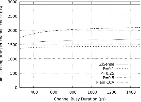
5.2 LPL Energy Consumption
We now assume TinyOS LPL as WSN MAC protocol to evaluate idle listening energy consumption of P-DCCA, ZiSense as T-DCCA and the classical CCA without any DCCA capability. We use LPL as WSN MAC protocol as ZiSense was particularly designed for this specific protocol.
0 500 1000 1500 2000
400 600 800 1000 1200 1400
Id
le
l
is
te
n
in
g
t
im
e
p
e
r
c
h
a
n
n
e
l
Channel Busy Duration (µs) ZiSense
[image:15.486.101.379.91.292.2]P=0.1 P=0.25 P=0.5 Plain CCA
Fig. 7. Energy consumption of P-DCCA and T-DCCA (based on ZiSense) under interference. P-DCCA requires less idle listening time under all channel conditions.
of a minimum packet duration of at least 500µs, 6 CCA checks spaced 500µs apart, over 3ms, are sufficient. This channel check behaviour is necessary for DCCA and plain CCA to check for incoming transmissions.
This behaviour can be illustrated using Figure1. For ZiSense the receiver CCA shown in Figure1 is performed over a long period of 2.9ms. For DCCA and plain CCA the receiver CCA consists of 6 CCA checks spaced 500µsapart, over 3ms.
ZiSense and plain CCA has a constant energy cost per channel check. However, plain CCA would not be able to infer the nature of the channel occupier and any observation of interference would lead to a false wake-up, contributing significantly to energy consumption; we do not consider this aspect here and include plain CCA only as reference point. P-DCCA has a variable energy cost which depends on the present interference signal.
Based on this, the radio-on time per DCCA check for P-DCCA, ZiSense and plain CCA are shown in Figure7, for interference conditions described byp =0.1,0.25,0.5 and variable durationt.
Plain CCA has the same energy cost as P-DCCA when interference approaches zero. P-DCCA has an energy cost which is much lower than that of ZiSense. Given that P-DCCA was shown in Section4to have at least similar detection accuracy as ZiSense P-DCCA will provide better energy efficiency when considering DCCA as receiver mechanism.
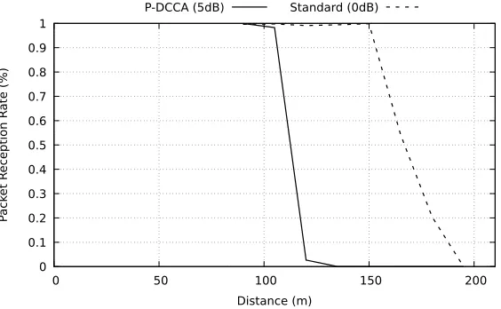
6 RANGE EVALUATION
P-DCCA requires transmission power variation which means that a signal cannot be transmitted continuously with full power. Hence, it has to be assumed that the achievable transmission range is reduced. In this evaluation we evaluate the impact of transmit power variation on the achievable communication distance.
0 0.1 0.2 0.3 0.4 0.5 0.6 0.7 0.8 0.9 1
0 50 100 150 200
P
ack
et R
eception R
ate (%)
Distance (m)
[image:16.486.100.382.88.262.2]P-DCCA (5dB) Standard (0dB)
Fig. 8. Link distance for P-DCCA and without power variation. P-DCCA power variation leads to a reduction of communication distance. P-DCCA achieves 100% PRR up to105mcompared to150mwithout P-DCCA.
strength loss is a function of the distance between sender and receiver, P-DCCA links will have a shorter communicable distance, compared to uniform transmission power.
We use two TelosB nodes configured as sender and receiver; the former is programmed to transmit 90 byte packets at a rate of 16 packets/second; the latter records each packet received to a buffer in RAM. These results are then retrieved by a host computer after the experiment. The experiment takes place outside in an empty sports field, and the distance between the nodes is varied from 90mto 180m, in increments of 15m. PRR is recorded for 3 minutes, for each distance. For each increment, the PRR is calculated. The transmitter node does not implement CCA checks or retransmissions, and neither node duty cycled the radio. Both nodes are elevated 75cmabove the ground to ensure line of sight.
Two P-DCCA configurations are used:PT = 0dBwhich is the uniform transmission power;
PT =5dBwhich is the setting used for the CC2420 implementation. The results are shown in
Figure8.
PRR follows the same pattern with both transmission powers: 100% PRR up to a cutoff point, beyond which no packets are received. The receiver can compensate bit errors up to a point where the packet cannot be successfully reconstructed. The transitional region between 100% PRR and 0% is often very small as in this experiment (see Petrova et al. [19]). ForPT =5dB, this distance is 105m. By contrast, using the maximum uniform transmission power,PT =0dB, this range is extended to 150m. Therefore, P-DCCA in this implementation incurs a reduction in link range of approximately 30%.
The reduced link range is the main drawback of using P-DCCA. In a large, multi-hop network, more hops may be needed to communicate, increasing energy consumption and offsetting the benefits of P-DCCA. Otherwise, if nodes are too sparsely deployed, P-DCCA may fragment the network and prevent communication entirely. P-DCCA may therefore be better suited to either smaller networks, with few nodes, or large, multi-hop networks, with many possible links.
CCA threshold selection to balance PRR and energy consumption.
Even though it might be generally possible to receive a packet at a specific distance, the receiver may not be able to clearly detect the incoming transmission using CCA. Thus, the limiting factor of maximum link distance in sensor networks may be detection of the incoming transmission rather than the ability to decode it successfully.
7 P-DCCA APPLICATION
To evaluate the benefit of P-DCCA in practice, we implemented it in a popular WSN MAC protocol: ContikiMAC. ContikiMAC with P-DCCA is then evaluated in a variety of testbed and practical deployments and the achievable network performance is evaluated and compared with plain ContikiMAC. The presented evaluation is specific to ContikiMAC; however, similar performance improvements are to be expected when applying P-DCCA to other WSN MAC protocols.
To include P-DCCA in a WSN MAC protocol it is necessary to replace the sender and receiver based CCA mechanism with the P-DCCA mechanism. It has to be taken into account that P-DCCA requires additional time compared to the standard CCA (see Section3). The additional time required depends on the used transceiver hardware and in many cases this additional required time does not require modifications to the MAC protocol. When transmitting messages the power modulation must be included.
7.1 P-DCCA in ContikiMAC
ContikiMAC [9] resembles other WSN MAC protocols (see section2) which use CCA for receiving and transmitting. To save power, ContikiMAC nodes keep the radio in a powered-down sleep state, and periodically listen for incoming packets once every duty cycle. Transmitters continuously transmit a strobe sequence back-to-back to the recipient, listening in between each packet for an acknowledgement. The operation of ContikiMAC is depicted in Figure9.
To listen for incoming packets, each node in the network uses two CCA spaced 0.5msapart; a busy channel detection from either causes the radio to be left powered-on to receive the next subsequent packet from the transmitter. Likewise, senders must check the channel is free using six CCA before transmitting, and one CCA between packet strobes - a single busy channel detection will cause the transmission to stop.
To reduce unnecessary transmissions when the receiver is asleep, Phase Lock (PL) is an optimisa-tion in ContikiMAC which learns the wake-up times of neighbouring nodes. Future transmissions are then delayed until just before the receiver is expected to wake.
P-DCCA allows us to improve ContikiMAC’s behaviour in interference environments as it enables us to implement fine-grained reaction to different interferer types. We decide to augment ContikiMAC with the following simple DCCA behaviour:
• Transmitter DCCA:Transmissions are only stopped in response to detecting 802.15.4 traffic, ignoring other channel interference.
• Receiver DCCA:The radio is only powered on to receive data after detecting 802.15.4 traffic, ignoring other channel interference.
Fig. 9. Normal Operation of ContikiMAC: 1) Transmit request is followed by Phase-Lock delay, and CCA check before transmitting. 2) Periodic Receiver CCA check detects incoming packet, entering receive-sequence. 3) After data received, ACK transmitted, and packet strobes stop.
short channel occupation time of the interferer. Transmitters only back off if 802.15.4 traffic is detected within a CCA before transmission.
ContikiMAC receivers avoid listening to the channel for incoming packets unless 802.15.4 traffic has been detected - reducing false wake-ups and improving energy efficiency. While inconclusive results are ignored, the risk of ignoring valid 802.15.4 packets is eliminated in the design of ContikiMAC: the 0.5msspacing between CCA checks ensures that at least one CCA check will not fall at the end of a packet in the strobe sequence (see Figure9).
In our evaluation we compare network performance of plain ContikiMAC and ContikiMAC with P-DCCA extension. In all setups the same network and interference configuration is used for ContikiMAC and ContikiMAC with P-DCCA.
7.2 Experiment 1: Single WSN Transmitter
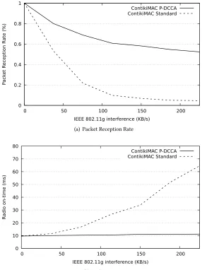
In the first experiment, the link performance and energy efficiency of ContikiMAC is measured in controlled interference conditions. Two Tmote Sky are placed in opposite corners in an unused office, spaced 6mapart. The nodes are connected to a host computer over a USB connection, used for reprogramming and communication. In the same office, an IEEE 802.11g access point and station are placed in opposite corners, and are connected to the host computer over a wired connection. Interference is generated using the D-ITG traffic generation tool [1], sending UDP traffic with varying intensity. The set traffic rates were achieved with present 802.15.4 traffic as the channel was not fully saturated. The experiment takes place during quiet office hours with reduced wireless background traffic in the building. WiFi channel 11 and IEEE 802.15.4 channel 22, which were found to be the quietest overlapping channels in the environment, are used for the experiment. 90-byte packets are sent at a rate of 4 packets per minute without retransmissions. The following performance metrics are recorded:
• Packet Reception Rate (PRR):PRR is a reflection of the link performance, and is the ratio of successful packet transmissions to total attempts.
• Radio-on Time Per Packet Received (RoT):RoT is used to measure the energy efficiency of ContikiMAC under interference. It is the time the transceiver is in an active state divided by the number of successfully received packets.
PRR and RoT are recorded at the receiver during the experiment. Each interference level is run for five minutes. The results are shown in Figure10.
0 0.2 0.4 0.6
0 50 100 150 200
P
ack
et R
eception R
ate (%)
IEEE 802.11g interference (KB/s)
(a) Packet Reception Rate
0 10 20 30 40 50 60 70 80
0 50 100 150 200
R
adio on-time (ms)
IEEE 802.11g interference (KB/s)
ContikiMAC P-DCCA ContikiMAC Standard
[image:19.486.96.382.94.476.2](b) Radio-on time
Fig. 10. ContikiMAC with standard CCA and P-DCCA. P-DCCA significantly improves packet reception rate and energy efficiency under interference.
becomes greater as interference increases. This is because as interference increases, the probability of a collision with ContikiMAC CCA increases. In case of standard ContikiMAC a collision results in an aborted transmission which leads to a PRR reduction. In case of ContikiMAC with P-DCCA the transmission is carried out (unless it is the case of a false negative P-DCCA classification) which is then often successful.
50 100 150 200 250 300 350 400
P-DCCA NO
-CCA
Standar
d
A
verage Thr
oughput per node
(Bytes/Sec)
[image:20.486.99.380.89.260.2]Num. TX. 1 2 4 8
Fig. 11. ContikiMAC Evaluation with multiple transmitters under WiFi interference. P-DCCA provides the greatest throughput compared to standard ContikiMAC and NO-CCA.
significantly worse performance, measuring 65msunder heavy interference, while the radio-on time of P-DCCA rises to only 12ms.
This experiment has shown that a simple DCCA policy on top of the P-DCCA mechanism significantly improves network performance. PRR is improved while energy consumption, expressed via RoT is reduced. For the highest measured interference level PRR is improved ten-fold, while RoT is reduced by 82%.
7.3 Experiment 2: Multiple WSN Transmitters
The previous experiment affirmed the benefits of P-DCCA in a single transmitter environment, where only one ContikiMAC node is transmitting. In this case, any interference detected is known to have originated from outside the network, such as from WiFi interference. However, in interference environments with multiple transmitters, CCA collisions may be due to either interference, or another WSN transmitter. In these cases, channel arbitration can be aided by P-DCCA. For example, upon collision with a WiFi signal, the more optimal approach in our implementation is to persist with the transmission. Conversely, collision with another ContikiMAC packet should result in the back off behaviour used within the WSN.
In this experiment, an IEEE 802.11g network generates interference at a fixed rate of 37.5KB/s. Sensor nodes use the ContikiMAC Carrier Sense Multiple Access (CSMA) to handle retransmissions, initiating a random back-off after every unsuccessful transmission attempt. On each node, upon an acknowledgement being received or a timeout, a new transmission is initiated - attempting maximum throughput. The average throughput per node is used as evaluation metric.
other transmitters being avoided, but nodes persisting when faced with WiFi interference. This experiment has shown that the P-DCCA mechanism significantly improves channel arbitra-tion in an interference environment. For example, when using 4 concurrent transmitters P-DCCA ContikiMAC improves throughput per node by 36% when compared with standard ContikiMAC.
7.4 Experiment 3: Testbed Deployment
Implementing P-DCCA with simple interferer-detection policies has been shown to reduce the energy costs and improve the PRR for individual links. The performance of P-DCCA in the context of a full network deployment (including routing protocol and multi-hop links), is evaluated next using a large scale WSN testbed.
The WISEBED [7] testbed at the University of Lübeck is used. This testbed is located on the 2nd floor of an office building, and consists of 162 nodes arranged in clusters of three. Each node is connected to a host laptop, and the testbed is coordinated over an ethernet backend, which allows for node reprogramming. To aid network configuration, all of the nodes have pre-allocated MAC addresses. For this experiment, only the TelosB nodes in the testbed are used.
All nodes are programmed with the Routing Protocol for Low-Power and Lossy Networks (RPL) routing protocol, which establishes an acyclic graph from a sink node to each node in the network. Each node then has a single parent, to forward data towards the sink, and a number of children, for downstream traffic. As RPL is used, the topology is not static and routing paths are subject to changes. The IPv6 protocol stack is used to handle packet forwarding and address assignment. The default Contiki CSMA behaviour is used to handle retransmissions, with an exponentially increasing back-off and a maximum retry limit of three.
Within the 49-node network, eight nodes are configured as sources. These generate a 60-byte packet every 30 seconds, sent to a single sink node located at one end of the deployment. The remaining nodes are part of the network, forwarding packets as required to the sink. The wakeup frequency of all nodes in the network was set to 8Hz.
It was necessary to generate repeatable and reliable interference under controlled parameters in the testbed. To achieve this, five of the TelosB nodes were programmed to simulate WiFi traffic, as described in JamLab [3]. These nodes used the test transmission mode of the CC2420, whereby psuedo-random data is transmitted continuously on the same IEEE 802.15.4 channel. The nodes alternate between maximum and minimum transmission power, to simulate packetised IEEE 802.11g traffic. Theonduration of the interference was 577µs, to simulate 1500-byte packet communication, including IEEE 802.11g RTS/CTS and acknowledgement. Theoff duration, reflecting the spacing between simulated IEEE 802.11g packets, was calculated randomly over a time window that is changed to throttle the degree of interference. This approach does not simulate the IEEE 802.11g MAC protocol, and does not coordinate between simulated interference. As a consequence, the degree of interference (which is used as the independent variable in this experiment) is per-interferer, and is not the sum of all interference during the experiment. This approach allows for an evaluation of P-DCCA over a multi-hop network in the presence of an interference source. In JamLab [3], the authors showed that this approach is able to achieve high accuracy of WSN performance compared to the emulated interferer. The arrangement of sink, sources, other nodes, and interferer nodes in the testbed are shown in Figure12.
Fig. 12. 54-node Wisebed Deployment in Lübeck, consisting of IEEE 802.11 interferer, source and sink nodes.
of packets sent from thenthsource node:Pn. From this, the average PRR fromN source nodes is calculated as:
PRRAver aдe=PPNReceived
n=1Pn
Also, all nodes in the network periodically reported the RoT of each node, every ten seconds. This is used to evaluate the energy efficiency of the network, in the same way as in the first experiment. The average RoT is calculated across all nodes in the network. P-DCCA and standard ContikiMAC variants are tested in 12 minute iterations, for each interference level. The experiment is repeated four times. The results are shown in Figure13.
The PRR results (Figure13(a)) are similar to the results obtained in the first experiment. The ContikiMAC P-DCCA variant is less affected by interference than standard ContikiMAC. In this experiment, however, P-DCCA also suffers severe packet loss under high interference rates. This may be due to the cumulative reduction in PRR which is felt across all links on a path - as opposed to the affect on an individual link as measured previously. Also, this experiment simulated interference originating from multiple IEEE 802.11 interferers, as opposed to a single, albeit higher power, interferer. Nevertheless, P-DCCA ContikiMAC clearly outperforms standard ContikiMAC in all interference conditions.
The energy consumption measured via RoT (Figure13(b)) shows similar trends to earlier ex-periments. The baseline under no interference is measured as 1.3ms. This is lower than the RoT measured for a single link (as in figure10(b)), as this is averaged across all nodes in the network -including nodes that do not participate in packet forwarding. As interference increases, the RoT increases drastically with standard ContikiMAC. DCCA mitigates this affect. This is due, in part, to the reduced rate of false wake-ups caused by collisions with interference, and also due to increased PRR with P-DCCA. As before, in this larger experiment, the energy efficiency of P-DCCA is less impervious to interference than in the previous smaller experiments.
These results confirm that P-DCCA benefits link quality and energy efficiency, on an individual link level, and also in large multi-hop networks. Importantly, the reduced transmission range stemming from P-DCCA power modulation does not impair packet delivery. This is due to either link availability or quality being relatively unimpaired by this power modulation, or whose affects are negligible in large networks. Consequently, these results show that the drawbacks of employing P-DCCA are far outweighed by the benefits, in this case.
0 0.1 0.2 0.3 0.4 0.5 0.6 0.7
0 10 20 30 40 50
P
ack
et R
eception R
ate (%)
Simulated-IEEE 802.11g Interference Rate (KB/s)
(a) Packet Reception Rate
0 10 20 30 40 50 60 70
0 10 20 30 40 50
R
adio
-on time per pack
et r
eceived (ms)
Simulated-IEEE 802.11g Interference Rate (KB/s) P-DCCA Standard
[image:23.486.95.386.88.478.2](b) Radio-on time
Fig. 13. Energy efficiency and PRR of ContikiMAC and P-DCCA in a large-scale deployment. Results show P-DCCA achieves lower energy consumption and higher packet delivery under interference.
measured interference level PRR is improved seven-fold while RoT is reduced by 85%. Reduced communication range due to the power variation has no negative impact in a relatively dense network setting such as the WISEBED testbed.
7.5 Experiment 4: Office Deployment
five minute intervals. The experiment lasts over 24 hours, and as before, PRR and RoT are recorded. The results of this experiment are shown in Figure14.
0 0.2 0.4 0.6 0.8 1
00:00 02:00 04:00 06:00 08:00 10:00 12:00 14:00 16:00 18:00 20:00 22:00 00:00
P
ack
et R
eception R
ate (%)
Time
P-DCCA Standard
(a) Packet Reception Rate
9 10 11 12 13 14 15 16 17
00:00 02:00 04:00 06:00 08:00 10:00 12:00 14:00 16:00 18:00 20:00 22:00 00:00
R
adio On T
ime (ms)
Time
P-DCCA Standard
[image:24.486.97.389.130.499.2](b) Radio-on time per packet received
Fig. 14. PRR and Radio-on time of ContikiMAC with and without P-DCCA in a busy office environment. Results show that P-DCCA improves network and energy efficiency throughout the experiment.
The results mirror earlier experiments: P-DCCA improves link performance and node efficiency in ContikiMAC under local RF interference. At peak office hours during this experiment, PRR was improved by up to 180%, and energy consumption reduced by up to 40%.
8 RELATED WORK
disadvantage 802.15.4 nodes and contribute to reduced network performance.
To mitigate the effects of interference on packet loss in WSN, Tang et al. present a solution based on CCA threshold adaptation [23]. Under WiFi interference, the authors show that CCA collisions are reduced by increasing the CCA threshold, thus improving packet delivery rate in the WSN. The authors present a solution that adaptively sets the CCA threshold based on the rate of transmit buffer overflows in a node. This approach is based on ZigBee, which has only one CCA check before transmitting. This is not the case for many WSN MAC protocols, which have multiple CCA per transmission.
Sha et al. similarly consider the CCA threshold in order to mitigate false wake-ups caused by interference [22]. The authors present AEDP, which attempts to raise the receiver CCA threshold in order to reduce false wake-ups, while keeping the threshold low enough however to ensure valid packets are still detected. In order to adapt to different environments, AEDP seeks this optimisation at runtime.
In both cases, these approaches rely on RSSI of interference to distinguish from WSN packets, which is not always guaranteed to be the case. This is not the case with P-DCCA, which modulates the transmission power of sent packets, which can then be detected by other WSN receivers.
Tang et al. present Interference Aware Adaptive Clear Channel Assessment (IAACCA), which more proactively contends for channel access by replacing the standard CCA [24]. Instead of a single CCA check, the channel is sampled continuously until found to be clear. IAACCA is shown to reduce packet loss under WiFi interference compared to standard CSMA mechanism. In the context of this work, IAACCA offers a policy decision after collision with interference, whilst P-DCCA is a replacement for the standard CCA. These works are therefore compatible, and may offer benefits if used in parallel.
Zheng et al. describe ZiSense [28], an active scanning technique in duty cycling MAC protocols to reduce false wake-ups. Similar to P-DCCA, ZiSense samples RSSI at high frequency, listening for timing and spectral characteristics indicative of 802.15.4. Based on these features, ZiSense presents one approach to realising DCCA, which we referred to as T-DCCA in Section3.7where it is discussed. By contrast, P-DCCA does not rely on signal characteristics inherent to 802.15.4 to detect incoming traffic. It instead modulates an identifiable signal to the output power of the transmitter, which requires less radio-on time to detect.
The accuracy of ZiSense and P-DCCA is evaluated empirically in Section4, and the energy consumption of both is compared theoretically in Section5. P-DCCA is shown to achieve greater accuracy, while requiring less listening time - hence further reducing the energy cost of idle listening.
Tang et al. [23] evaluates the available 802.15.4 CCA modes, energy thresholds and packet loss in the presence of WiFi interference. An adaptive method is proposed to set the energy threshold to achieve optimum performance. Our work goes further than modification of CCA thresholds and an entire new CCA method is proposed.
interference-specific responses for each transmission. We focus on shortening the detection time without sacrificing accuracy, differentiating only between 802.15.4 and non-802.15.4 interference. We find this to be sufficient for mitigating interference.
An experimental comparison with interference classification methods would be frivolous. Nonethe-less, comparing the results of our P-DCCA evaluation in Section4with these approaches, suggests comparable accuracy in detecting 802.15.4 transmissions.
Spectral avoidance has featured in literature as a mitigation approach to interference, ensuring coexistence by avoiding collisions entirely [17,26]. While effective in some situations, this method is ineffective in crowded circumstances, as free channels may become a scarcity. Liang et al. [15] describe how to bolster each packet’s resilience to the effects of interference through embedding multiple packet headers and by employing forward error correction. An Automatic Repeat Request scheme for retransmitting partially damaged packets is explored by Hauer et al. [12]. By scanning the RSSI at high frequency during packet reception, spikes from local interference are associated with corruptions in the packet. Our work is orthogonal to these aforementioned works, permitting parallel use to counter interference.
The benefits of a Coexistence Aware Clear Channel Assessment (CACCA) are explored by Tytgat et al. [25], followed by a CACCA evaluation using a Software Defined Radio (see [8]). In this existing work WiFi nodes are equipped with the ability to detect different network types while in our work we consider a CCA extension of 802.15.4 devices. Our proposed DCCA method requires no special hardware, operating on commodity sensor nodes.
In our previous work we have shown that DCCA [14] can help in general to improve network performance. However, in this previous work we have not detailed a mechanism such as P-DCCA that can be used to implement DCCA.
9 CONCLUSION
Given the current pace with which wireless devices are deployed network coexistence is an issue that must be taken into account when designing WSNs and wireless networks in general. DCCA is an effective building block for the implementation of coexisting networks. In this paper we have described and evaluated P-DCCA, a novel DCCA method implementable on current off-the-shelf WSN hardware. We contrasted P-DCCA with the alternative options of MD-DCCA and T-DCCA (using ZiSense as T-DCCA implementation).
multi-hop testbed deployments. The former saw packet reception rate improve ten-fold, and energy efficiency improve by over 80% under heavy WiFi interference. These improvements were achieved using simple policies which may not be optimal; better policies to react on P-DCCA outcomes may improve network performance even further.
P-DCCA is not designed to classify interference, rather to discern incoming transmissions from other noise, to achieve high accuracy without sacrificing energy efficiency, nor swaying too far from the standard CCA paradigm. One of our next steps will include the design of improved DCCA reaction policies. Another avenue of future work will be the integration of P-DCCA with other MAC protocols. The work has shown that DCCA is beneficial and we have demonstrated that P-DCCA is a valid implementation option.
ACKNOWLEDGMENTS
This work is partly funded by the Centre for Global Eco-Innovation, part financed by the European Regional Development Fund.
REFERENCES
[1] Stefano Avallone, S Guadagno, Donato Emma, Antonio Pescapè, and Giorgio Ventre. 2004. D-ITG distributed internet traffic generator. InQuantitative Evaluation of Systems, 2004. QEST 2004. Proceedings. First International Conference on the. IEEE, 316–317.
[2] Bastian Bloessl, Stefan Joerer, Fabian Mauroner, and Falko Dressler. 2012. Low-cost interferer detection and classification using TelosB sensor motes. InProceedings of the 18th annual international conference on Mobile computing and networking. ACM, 403–406.
[3] Carlo Alberto Boano, Thiemo Voigt, Claro Noda, K Romer, and Marco Zúñiga. 2011. Jamlab: Augmenting sensornet testbeds with realistic and controlled interference generation. InInformation Processing in Sensor Networks (IPSN), 2011 10th International Conference on. IEEE, 175–186.
[4] Michael Buettner, Gary V Yee, Eric Anderson, and Richard Han. 2006. X-MAC: a short preamble MAC protocol for duty-cycled wireless sensor networks. InProceedings of the 4th international conference on Embedded networked sensor systems. ACM, 307–320.
[5] Kaushik R Chowdhury and Ian F Akyildiz. 2009. Interferer classification, channel selection and transmission adaptation for wireless sensor networks. InCommunications, 2009. ICC’09. IEEE International Conference on. IEEE, 1–5. [6] Moteiv Corporation. 2005. Tmote Sky Ultra low power IEEE 802.15. 4 compliant wireless sensor module.Datasheet:
http://www. sentilla. com/pdf/eol/tmote-skydatasheet. pdf (2005).
[7] Geoff Coulson, Barry Porter, Ioannis Chatzigiannakis, Christos Koninis, Stefan Fischer, Dennis Pfisterer, Daniel Bimschas, Torsten Braun, Philipp Hurni, Markus Anwander, et al. 2012. Flexible experimentation in wireless sensor networks.Commun. ACM55, 1 (2012), 82–90.
[8] Peter De Valck, Lieven Tytgat, Ingrid Moerman, and Piet Demeester. 2013. Coexistence Aware Clear Channel Assessment. InWireless Sensor Networks. Springer, 165–178.
[9] Adam Dunkels. 2011. The contikimac radio duty cycling protocol. (2011).
[10] Adam Dunkels, Bjorn Gronvall, and Thiemo Voigt. 2004. Contiki-a lightweight and flexible operating system for tiny networked sensors. InLocal Computer Networks, 2004. 29th Annual IEEE International Conference on. IEEE, 455–462. [11] Jan-Hinrich Hauer, Vlado Handziski, and Adam Wolisz. 2009. Experimental study of the impact of WLAN interference
on IEEE 802.15. 4 body area networks. InWireless sensor networks. Springer, 17–32.
[12] Jan-Hinrich Hauer, Andreas Willig, and Adam Wolisz. 2010. Mitigating the effects of RF interference through RSSI-based error recovery. InWireless Sensor Networks. Springer, 224–239.
[13] Texas Instruments. 2006. CC2420: 2.4 GHz IEEE 802.15. 4/ZigBee-ready RF Transceiver. Available at Available at http://www. ti. com/lit/gpn/cc2420(2006), 53.