PERFORMANCE ANALYSIS OF CONVERGING DIVERGING NOZZLE
Mohini
1, Er Kriti Srivastava
2, Er Shweta Mishra
3, Er Akhil Vikram Yadav
41
M. Tech student, Mechanical Engineering, IET Dr. R.M.L Avadh University, Ayodhya, India
2,3 &4
Assistant Professor, Mechanical Engineering Dept., IET Dr. R.M.L Avadh University, Ayodhya, India
---***---
Abstract:-
Nozzle produced thrust and convert thermal energy of hot gases into kinetic energy. The purpose of nozzle is toexpand gases as efficiently as possible to maximize exit velocity. Nozzle is useful in supersonic flow to attain speed greater than the speed of sound. Computational fluid dynamics (CFD), is use to compute flow of nozzle with different mach numbers and different divergent angle of the nozzle. In the present work, CD nozzle is designed by using CFD for a particular divergent angle in 2D model. Further analysis and comparison is done for various other cases by changing divergent angle of nozzle. CFD replaces continuous domain with discrete using grid, numerical methods and algorithms to solve and analyze problems involving in fluid flow. In this dissertation work is carried out in ANSYS Fluent 15.0 for modeling and analysis of flow for supersonic nozzle.
KEY WORDS: Convergent divergent nozzle, degree of angle, Mach number, computational fluid dynamics.
1. INTRODUCTION
A nozzle is used to control the direction of flow, mass, shape, pressure, rate of flow and speed of the stream that is exhausted from nozzle. Flow velocity increases means some other form of energy must decreases. In this case temperature and pressure both will decreases and velocity increases. [1] A De-Laval nozzle is an example of CD nozzle which was invented by a Swedish inventor Gustaf De-Laval. In all modern rocket engine that used hot gas combustion use level nozzle. The gas flow through a de-level nozzle is isentropic(less friction and less heat dissipation). De-Laval nozzle works on converting pressure energy from the fuel flow and heat energy from the combustion of fuel into kinetic energy in the form of high exhaust velocity.[2] In converging section of nozzle area is decreasing to minimum and then area is expanding back out to maximum in diverging section.[3] Engines are most efficient when the exhaust is at the same pressure as the ambient pressure outside of the engines so for rocket engines which will be used at sea level where ambient pressure is relatively high the expansion ratio will be pretty low so the exhaust stays at about one atmosphere pressure when it leaves the nozzle for rocket engine which will be used in the upper atmospheric or in space the ambient pressure will be must lower so the expansion ratio will be much higher. This is why upper stage engines usually have a very large engine pill, first stage engines have to work at a variety of pressure as they climb through the atmosphere is only one pressure where these engines have maximum efficiency, all other altitudes they run at slightly lower efficiency there have been some attain to minimize these loss by designing engine nozzle that work well at altitude. So the nozzle is very important part of the rocket engine which is use to take the heat and pressure
produce by all other parts of the engine and transform all of that energy into thrust.
2. METHODOLOGY ADOPTED
In the present study, the certain methodology has been followed which give optimum result to complete our study for CFD analysis of CD nozzle. First a 2-D model is generated by using ANSYS software then mesh is created, next step is defining operating condition, material selection, and boundary condition for solving the equation,
after that result is analyzed. Deshpande ND et. al [2018]
reported that results obtained by theoretical data are almost same as result obtained by (CFD) analysis. [4] We have used these data in for the designing of nozzle.
Table 1 dimension of nozzle
Parameter dimension
Diameter of inlet 166.6(mm)
Diameter of throat 34.5(mm)
Diameter of outlet 183(mm)
Length of chamber 99.93(mm)
Convergent angle 32o
© 2019, IRJET | Impact Factor value: 7.34 | ISO 9001:2008 Certified Journal | Page 25
Fig-1: Two dimensional design of nozzleFig-2: Meshing of nozzle Selected condition given in table-
Table 2- problem setup
General Solver type- density based
2D space planer
Models Energy equation- ON
Viscous model- Laminar
Materials Density- ideal gas
Specific heat- 1880( j/kg-k)
Thermal conductivity-
0.0142(w/m-k)
Viscosity- 8.983e-05(kg/m-s)
Molecular weight-
27.7(kg/kg-mol)
Boundary conditions Inlet pressure-100 bar
Inlet temperature- 3300K Outlet temperature- 1700K
Table 3- solution setup
Solution controls Courant number- 5
Solution initialization Compute from- Inlet
Run calculation No. of iteration- 1000
3. RESULT AND DISCUSSION
After describing all parameters iteration is performed then results in form of various contour, vector or grid display plots are generated through this software.
3.1- Divergent angle 11.31 degree
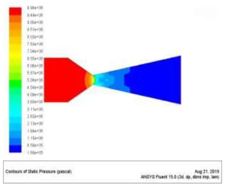
Pressure contour- we get maximum pressure 9.981e+06 Pascal at inlet. On moving towards the throat the pressure starts decreasing and at the throat it is found as 7.089e+06 Pascal. Pressure at the outlet of nozzle is 1.69e+05 Pascal.
Fig-3: Pressure contour at angle 11.31degree
[image:2.612.54.272.273.366.2]Velocity contour- Air enters the nozzle at a pressure of 1e+07 Pascal. Velocity contour shows the direction and magnitude of the velocity. The magnitude of velocity is more at the exit which is 2.34e+03 m/s. At the throat we can see the velocity is nearer to 1.23e+03 m/s and at inlet it is 1.17e+02 m/s it shows velocity increases from inlet to outlet.
[image:2.612.347.559.554.711.2]Temperature contour- Temperature at the inlet is higher, we get the value of temperature is 3.30e+03 K and at outlet it is 1.85e+03 K, means temperature decreases from inlet to outlet.
Fig-5: Temperature contour at angle 11.31degree Mach number contour- From figure it is clearly visualized that at throat we get value of Mach number is 1.21 (sonic) and at outlet we get maximum value of Mach number 2.87 (supersonic). Mach no increases from inlet to outlet. [5]
Fig-6: Mach number contour at angle 11.31degree 3.2- Divergent angle 20 degree
Pressure contour- We get maximum pressure 9.981e+06 Pascal at inlet. On moving towards the throat the pressure
starts decreasing and at the throat it is found as 7.88e+06 Pascal. At outlet pressure is 1.07e+05 Pascal.
Fig-7: Pressure contour at angle 20 degree
Velocity contour- The magnitude of velocity is more at the exit which is 2.39e+03 m/s. At the throat we can see the velocity is nearer to 1.23e+03 m/s and at inlet it is 1.19e+02 m\s. it means velocity increases from inlet to outlet.
Fig-8: Velocity contour at angle 20 degree
© 2019, IRJET | Impact Factor value: 7.34 | ISO 9001:2008 Certified Journal | Page 27
Fig-9: Temperature contour at angle 20 degreeMach number contour- From figure it is clearly visualized that at throat we get value of Mach number is 1.22 (sonic) and at outlet we get maximum value of Mach number 2.99 (supersonic).
Fig-10: Mach number contour at angle 20 degree 3.3- Divergent angle 30 degree
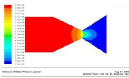
Pressure contour- We get maximum pressure 9.98e+06 Pascal at inlet. On moving towards the throat the pressure starts decreasing and at the throat it is found as 7.0887e+06 Pascal. At outlet pressure is 8.30e+04 Pascal.
Fig-11: Pressure contour at angle 30 degree Velocity contour- The magnitude of velocity is more at the exit which is 2.42e+03 m/s. At the throat we can see the velocity is nearer to 1.23e+03 m/s and at inlet it is 1.21e+02 m/s. it means velocity increases from inlet to outlet.
Fig-12: Velocity contour at angle 30 degree
Fig-13: Temperature contour at angle 30 degree
[image:5.612.338.558.166.277.2]Mach number contour- From figure it is clearly visualized that at throat we get value of Mach number is 1.28 (sonic) and at outlet we get maximum value of Mach number 3.07 (supersonic).
Fig-14: Mach number contour at angle 30 degree
3.4- Divergent angle 40 degree
Pressure contour- We get maximum pressure 9.99e+06 Pascal at inlet. On moving towards the throat the pressure starts decreasing and at the throat it is found as 7.026e+06 Pascal. At outlet pressure is 1.63e+05 Pascal.
Fig-15: Pressure contour at angle 40 degree
[image:5.612.55.269.313.472.2]Velocity contour- The magnitude of velocity is more at the exit which is 2.34e+03 m/s. At the throat we can see the velocity is nearer to 1.29e+03 m/s and at inlet it is 1.17e+02 m/s. it means velocity increases from inlet to outlet.
Fig 16- Velocity contour at angle 40 degree
[image:5.612.337.559.363.474.2]Temperature contour- Temperature at the inlet is higher, we get the value of temperature is 3.30e+03 K and at outlet it is 1.84e+03 K. means temperature decreases from inlet to outlet.
Fig-17: Temperature contour at angle 40 degree
Mach number contour- From figure it is clearly visualized that at throat we get value of Mach number is 1.28 (sonic) and at outlet we get maximum value of Mach number 2.88 (supersonic).
[image:5.612.341.560.558.685.2] [image:5.612.56.265.579.706.2]© 2019, IRJET | Impact Factor value: 7.34 | ISO 9001:2008 Certified Journal | Page 29
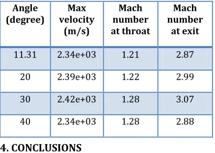
Comparison of velocity and Mach numberTable 4- Various parameters at different Angle
4. CONCLUSIONS
Following conclusion were found in the analysis of CD nozzles at different diverging angle.
It is observed from pressure, temperature and velocity
contour that value of pressure and temperature is higher at inlet and falling down with the length of the nozzle while velocity is lower at the inlet location and it goes up with the length of the nozzle.
At the throat of the CD nozzle, when the divergence
angle is 30 degree Mach number is 1.28 and at divergence angle of 11.31 degree Mach number is 1.21. At 11.31 degree angle Mach number is increasing up to 2.87 while for divergence angle of 30 degree the Mach number is increasing up to 3.07
In the nozzle due to the effect of wall friction and
viscosity, Mach number decreases near the wall.
On comparing all nozzles at different diverging angle it is
found that Mach number increases with increment in diverging angle and at 30 degree Mach number at outlet is higher after that it start decreasing.
To obtain a higher velocity we can go with 30 degree of
diverging angle because at this point velocity is maximum.
REFERENCES
1. Natta P, Kumar VR, Rao YH. “Flow analysis of rocket nozzle using computational fluid dynamics (CFD).” International Journal of Engineering Research and Applications, Volume-2, Issue-4; Sept 2012
2. Kumar G, Baraskar S. “Literature survey on nozzle throat analysis.”International Journal of Advance Research and Innovative Ideas in Education, Volume-4, Issue-4; 2018
3. Kumar U, Rajput SS, Borkar P. “CFD analysis and parameter optimization of Divergent Convergent Nozzle.” International Journal of Advance Research and Development, Volume-3, Issue-10; 2018
4. Deshpande ND, Vidwans SS, Mahale PR, Joshi RS, Jagtap KR. “Theoretical and CFD Analysis of De-Laval Nozzle”. International Journal of Mechanical and Production Engineering, Volume-2, Issue-4; April 2014
5. Rao GR, Ramakanth US, Lakshman A. “Flow analysis in a convergent-divergent nozzle using CFD”. International Journal of Research in Mechanical Engineering, Volume-1, Issue-2; Oct 2013:136-44.
6. Biju Kuttan P, Sajesh M. “Optimization of divergent angle of a rocket engine nozzle using computational fluid dynamics”. Volume-1, Issue-2; 2013:196-207.
Angle
(degree) velocity Max (m/s)
Mach number at throat
Mach number
at exit
11.31 2.34e+03 1.21 2.87
20 2.39e+03 1.22 2.99
30 2.42e+03 1.28 3.07