© 2019, IRJET | Impact Factor value: 7.34 | ISO 9001:2008 Certified Journal
| Page 433
“SEISMIC EFFECT OF RIGID FLOOR DIAPHRAGM”
Md Aziz Ur Rahman
1, Asst. Prof. Navilesh Jamshetty
21
Student., Civil Engineering, Faculty of Engineering & Technology (Co-Education) Sharnbasva University
kalaburagi, karnataka, India
2
Asst. Prof, Civil Engineering, Faculty of Engineering & Technology (Co-Education) Sharnbasva University
kalaburagi, karnataka, India
---***---Abstract - In this study, seismic analysis of multi storey RC building frames has been carried out considering rigid diaphragm. A floor diaphragm system is area unit terribly economical in resisting lateral forces. ETABS 2016 software has been used for analysis purpose. Analyses of multi structure RC building frames area unit dole out in building frame with floor diaphragm. Two different type of floor diaphragm are used i.e. semi rigid diaphragm and rigid diaphragm. Results are collected in terms of story drift, maximum storey displacement, base shear and time period. Which are basically broke down to evaluate the impacts of different parameters this methodology centers around the diverse kind of floor stomach nature in a structure and their viability in diminishing the sidelong removal and minute at last to accomplish economy in development with comparable auxiliary edges.
Key Words: Seismic, Floor diaphragm, Maximum Storey drift, Maximum Base shear, Storey displacement, Time period
1. INTRODUCTION
All in all, the RC structures gravity stacking, for example, Infill block dividers, self-weight of individuals doesn't cause much impact on the structure, yet the horizontal loadings, for example, Earthquakes and wind loadings which can incite bigger measure of parallel powers in the structure which impacts in disappointment.
The RC confined structure loaded up with infill divider has more noteworthy firmness rather than RC surrounded structure without infill brick work, in light of the fact that the infill stone work divider upgrades the strength of structure all through the versatile stage. A RC structure ought to be along the side hardened this can be acquired by giving infill dividers. The structure comprising of SS have less firmness as opposed to building having without delicate story
Reinforced concrete diaphragms (floors and rooftops) of a structure tie the vertical auxiliary components, (for example, dividers and edges) together to enable structures to oppose outside burdens, for example, Gravity and parallel powers from seismic occasions or wind activity. Floor diaphragms play a crucial role of transferring forces from the structure to the lateral force resisting parts that then transfers the forces
from the structure to the bottom. The extents and methods for interior powers inside solid floor stomachs square measure fundamentally extra confused than those expected by some basic ways utilized in current style pursue, similar to the Equivalent Static Analysis (ESA) technique.
The ESA method is utilized around ninetieth of the ideal opportunity for basic style, in light of its straightforwardness and power. The ESA technique has been found by different analysts to under-gauge the quickening of floors, especially in the lower levels of the structures prompting poor forecasts of the basic reaction.
1.1 TYPES OF DIAPHRAGM
RIGID DIAPHRAGM
SEMI RIGID DIAPHRAGM
FLEXIBLE DIAPHRAGM
Rigid diaphragm
In the rigid floor diaphragm, the lateral forces are distributed to the vertical load resisting elements (frames, shear walls) in proportion to their relative stiffness’s. In the rigid diaphragm thought, the in-plane displacement is considered to be equal along its entire length under lateral load. This rigid diaphragm thought is cheap for building nearly sq. in arrange. A case-in-plane concrete floor is Associate in nursing example of rigid diaphragm.
Semi-rigid diaphragm
© 2019, IRJET | Impact Factor value: 7.34 | ISO 9001:2008 Certified Journal
| Page 434
with cheap assumptions, the semi-rigid diaphragm will be created on a diaphragm's rigidity or flexibility however in some cases the diaphragm deflection and the vertical lateral load-resisting (VLLR) elements can be of same magnitude only in semi-rigid diaphragm
Flexible Diaphragms
Flexible diaphragms distribute loads to elements which connect to them solely based on the tributary area of the element within the plane of the diaphragm. A flexible diaphragm is Roofs or floors similarly as, however not essentially restricted to that pod like with ply board, wood decking, or metal decks while not structural concrete topping slabs. Metal decks with lightweight fill may or may not be flexible. Diaphragms area unit thought-about versatile once the utmost lateral deformation of the diaphragm is over twice the common story drift of the associated story. This may be determined by comparison the computed center in-plane deflection of the diaphragm itself beneath lateral load with the drift to adjacent vertical components beneath tributary lateral load.
1.2 LITERATUREREVIEW
D. R. Gardiner et.al: (look into examines the extent and patterns of powers in solid floor stomachs, with an accentuation on exchange powers, under seismic stacking. This examination thinks about the ensuing things: mechanical marvel powers that create from the quickening
of the ground mass; move powers that create from the collaboration of sidelong power opposing parts with entirely unexpected twisting examples, for example, divider and casing components; and variety of exchange powers because of various qualities and solidness of the auxiliary components
Joel M. Barron and Mary Beth D. Hueste (2004): dissected under seismic stacking, floor and rooftop frameworks in strengthened cement (RC) structures go about as stomachs to move horizontal tremor burdens to the vertical parallel power opposing framework (LFRS). In current pursue, level stomachs are ordinarily thought to be inflexible, therefore disregarding the impact of their in plane development in respect to the vertical LFRS.
M.M. El-Hawary (1994): explores the significance of including the impacts of the adaptability of the level stomachs when utilizing the P-delta strategy for examination, particularly when considering the heaps connected to middle of the road outlines on supports that are not part of the horizontal power opposing framework. Examinations were led for basic frameworks with a variable number of stories, number of inlets and stomach firmness' and upheld by unbending jointed plane casings or vertical brackets.
Seong-Kwon Moon and Dong-Guen Lee (1994): embraced the unbending floor stomach supposition for the investigation of multistory structure structures as a result of the straightforwardness in the examination system.
Anderson et.al (2005: created scientific models exploitation business pc programs, SAP 2000 and ETABS to gauge the seismic exhibition of low-ascent structures with solid dividers and adaptable stomachs. Once more, openings weren't a piece of the models concocted. Barron and Hueste (2004) assessed the effect of stomach adaptability on the auxiliary reaction of 4 structures having 2:1 and 3:1 set up plan proportions and were 3 and 5 stories tall, severally
2. OBJECTIVES
A detailed literature review is dispensed to outline the objectives of the thesis. The literature review is mentioned thoroughly in Chapter two and in brief summarized as follows:
To compare buildings with different lateral resisting system with regard to their time period, base shear, story float and relocation. The variation in the distribution of inertia forces, leads to change in the distribution of the shear forces and bending moments in the diaphragm.
It Resist gravity loads.
© 2019, IRJET | Impact Factor value: 7.34 | ISO 9001:2008 Certified Journal
| Page 435
diaphragm
The dynamic characteristics of the building with rigid diaphragm, and consequently its response to seismic ground motion are different from that of a building with flexible diaphragm.
To observe the results of flexible & semi-rigid diaphragm are identical.
Flexural Stiffness of the Slab plays vital role in Transferring of Forces through Diaphragm action to the Vertical lateral force resisting elements
Following steps have been adopted in this study
A thorough literature review to understand the seismic evaluation of building structures and application of pushover analysis and time history analysis.
Select a current structure with stomach brokenness.
Design the building as per prevailing Indian Standard for dead load, live load, and Earthquake load.
Analyze the structure utilizing direct/nonlinear static/powerful examination techniques.
Analyze the results and arrive at conclusions.
4. METHODS OF ANALYSIS
It is an endeavor to research the impact of Irregular arrangement setup for multistoried fortified solid structure model. This venture principally underlines on investigation of a multi-story building (G+12) which is sporadic both in plan and height. Demonstrating of 13 storeyed R.C.C. encircled structure will be done on the ETABS programming for investigation. Post examinations of the structure, for example, Maximum Story Displacement, Base Shear, Story Drift, and timeframe are processed and after that looked at for all the broke down cases.
Here the examination is done for the conduct of G+12 Storied Buildings, Floor tallness gave as 3m and furthermore properties are characterized for the structure. The model of structures is made in ETABS programming. The seismic zone considered is zone II and soil type is medium. The displaying of structure is accomplished for Indian Seismic Zone II, IS 1893-2002.For given structure, stacking with connected burdens incorporates live burden, quake burden and dead burden are as indicated by IS 875 section I, part II and
IS1893-2002 individually. Investigation is completed by Response Spectrum Analysis utilizing ETABS programming. The examination is completed to decide greatest hub removal and base shear. After investigation, results are gotten as charts which are thus seen to frame ends.
Methods for Seismic analysis of buildings may be classified as follows:
Equivalent Static Analysis (Linear Static)
Response Spectrum Analysis (Linear Dynamic)
Time History Analysis (Nonlinear Dynamic)
4.1 EQUIVALENT STATIC FORCE METHOD
This method of finding the design lateral force is also known as equivalent static method or seismic coefficient method or linear static method or equivalent static method. This method is found to be simple method as it requires less computational effort and is based on the formulae as per the code of practice. First the structure base shear is registered for the entire given structure and after that the came about base shear is appropriated up and down the stature of the structure. The parallel power at each floor level is appropriated to singular horizontal burden opposing components.
Seismic Base Shear (Vb)
The design seismic base shear (Vb) or the total design lateral force along any principle direction is computed by using the below relation
Vb = Ah x W
Where
Ah = Design Horizontal Acceleration Spectrum Value, using the fundamental natural period (T) in the considered direction of vibration and it can be determined by the relation
Ah = 𝑍2∗𝐼𝑅∗𝑆𝑎𝑔
Z = Seismic Zone Factor 13
I = Importance Factor
R = Response Reduction factor
Sa/g = Response Acceleration Coefficient.
W= Seismic Weight of the Building
Seismic Weight (W)
© 2019, IRJET | Impact Factor value: 7.34 | ISO 9001:2008 Certified Journal
| Page 436
each floor is sum of its full dead load and the appropriate amount of live load or imposed load.
4.2 RESPONSE SPECTRUM METHOD
Reaction Spectrum Analysis strategy (RSA) ought to be performed utilizing the plan range by a particular plan range of a site, which is explicitly arranged for a structure at the specific undertaking site.
This strategy is otherwise castled a straight powerful technique for investigation. In this technique, the seismic tremor reaction (or Design) range legitimately gives the pinnacle reaction of a structure during a quake. For the basic plan applications this strategy gives very exact outcomes. In this technique, various methods of reaction of a structure to a tremor are considered. At that point for every mode, a reaction is perused from the structure range, in light of the modular recurrence and the modular masses. The reactions of the various modes are then joined to give a gauge of the all out reaction of the structure utilizing the modular blend techniques, for example, Square foundation of Sum of Squares (SRSS), Complete Quadratic Combinations (CQC), or Absolute Sum (ABS) strategy.
4.3 TIME HISTORY ANALYSIS
Nonlinear dynamic Associate in Nursingalysis utilizes the combination of ground motion records with an comprehensive structural model, thus is capable of producing results with relatively low uncertainty In nonlinear unique examinations, the cautious auxiliary model exposed to a ground-movement record produces assessments of half disfigurements for each level of opportunity among the model and on the modal responses square measure combined mistreatment schemes like the square-root-sum-of-squares.
5. ANALYTICAL MODELING
GENERAL
Seismic analysis codes of the building prescribe the method of analysis based on whether the building is regular or irregular. Majority of the codes recommends the use of linear static analysis for symmetric and selected class of regular buildings. The code suggests the use of dynamic analysis methods for the irregular configurations of the buildings the codes of seismic analysis prescribes the different methods to carry out lateral load analysis during the analysis and design the infill wall and it's effect is usually ignored. In the present study, the code for seismic analysis is followed for the lateral load analysis. ETABS is used for performing the analysis.
5.1 DESCRIPTION OF THE MODELS
Here in this study we have considered 8 models for the study.
Rigid floor diaphragm models
Regular model with rigid diaphragm
Regular model with shear wall in X direction.
Regular model with shear wall in Y direction.
Regular model with shear wall in both X & Y direction
Semi Rigid floor diaphragm models
Regular model with semi rigid diaphragm
Regular model with shear wall in X direction.
Regular model with shear wall in Y direction.
Regular model with shear wall in both X & Y direction
Pushover analysis and time history analysis.
Select a current structure with stomach brokenness.
Design the building as per prevailing Indian Standard for dead load, live load, and Earthquake load.
Analyze the structure utilizing direct/nonlinear static/powerful examination techniques.
© 2019, IRJET | Impact Factor value: 7.34 | ISO 9001:2008 Certified Journal
| Page 437
PLAN OF THE RESIDENTIAL BUILDING
BUILDING DETAILS:
Type of building Residential Building
No of stories
Total height of building
13 stories 42 m
Thickness of walls 230mm (main wall) and 100mm (partition wall)
Live load
3KN/m2 – Balcony , Corridor 2KN/m2 – All rooms
Grade of Concrete M35
Grade of reinforcing Steel Fe500 , Fe415
Density of brick masonry 8KN/m2 (AAC-Auto aerated concrete blocks)
Sizes of columns
C1=300mmX600mm C2=300mmX900mm C3=300X1050mm Sizes of beams
Thickness of slab
B1=230X530mm B2=300X600mm 150mm
Zone II
Soil type II
Importance factor 1.2 Response reduction 5
Seismic zone factor 0.1 for zone II
Damping ratio 5%
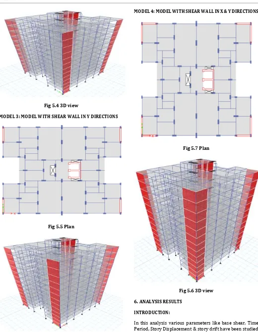
[image:5.595.25.564.71.772.2]MODEL 1: REGULAR MODEL G+ 12 STORIES
Fig 5.1 Plan
Fig 5.2 3D view
[image:5.595.309.569.106.382.2]MODEL 2: MODEL WITH SHEAR WALL IN X DIRECTIONS
[image:5.595.30.292.137.503.2]© 2019, IRJET | Impact Factor value: 7.34 | ISO 9001:2008 Certified Journal
| Page 438
Fig 5.4 3D view
MODEL 3: MODEL WITH SHEAR WALL IN Y DIRECTIONS
Fig 5.5 Plan
Fig 5.6 3D view
[image:6.595.37.291.88.296.2]MODEL 4: MODEL WITH SHEAR WALL IN X & Y DIRECTIONS
Fig 5.7 Plan
Fig 5.6 3D view
6. ANALYSIS RESULTS
INTRODUCTION:
[image:6.595.254.549.100.674.2]© 2019, IRJET | Impact Factor value: 7.34 | ISO 9001:2008 Certified Journal
| Page 439
DESIGN SEISMIC BASE SHEAR
Base Shear is only the distinguishing proof of the normal greatest sidelong powers which can happen as a result of the ground shaking at the base of the structure. The underneath table demonstrates the estimations of seismic base shear for different models acquired by the 3 distinctive examination strategies like, ESA, RSA. The base shear hand-off on the state of the site on which the structure needs to stand and furthermore the dirt strata which is in charge of moving burden and bearing the heaps.
MODEL MAXIMUM BASE SHEAR KN RIGID SEMIRIGID X-Dir Y-Dir X-Dir Y-Dir
1 1195 5654 734.64 3365.14
2 1460 5876 886.34 3610.78
3 1351 6808 803.89 4028.23
[image:7.595.290.570.54.429.2]4 1700 7394 1012.78 4415.86
FIG 6.1: BASE SHEAR KN
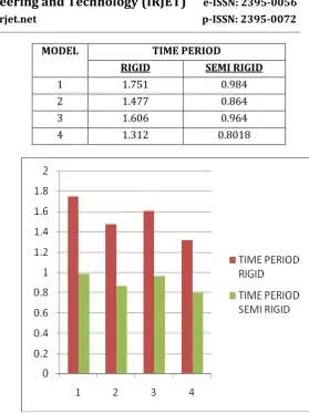
TIME PERIOD:
It is only the free vibration of the structure which is undammed. The estimations of time period acquired by the investigation utilizing etabs. The table demonstrates that timeframe is progressively changes with the distinctive investigation technique. As the structure isn't comparative and henceforth time period fluctuates. It is seen that model 8 has the most noteworthy time period as it comprises of Soft story and examination is made with different estimations of the model.
MODEL TIME PERIOD
RIGID SEMI RIGID
1 1.751 0.984
2 1.477 0.864
3 1.606 0.964
4 1.312 0.8018
FIG 6.2: TIME PERIOD CALACULATION
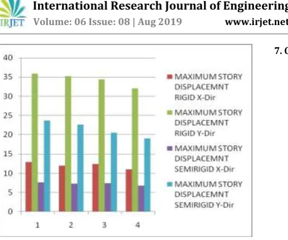
STORY DISPLACEMENT:
Storey displacement, movement of the story laterally with respect to the base it is total displacement of its storey with respect to ground. The different displacement values for the different models have been plotted and noted below. This Story displacement is obtained by perfuming analysis using ETABS with application of different analysis procedures. It is seen that the displacement under EQA method is higher compared to the other two methods for different models, as the models consists of different aspects like SW, CW & SS.
MODEL MAXIMUM STORY DISPLACEMNT MM
RIGID SEMIRIGID
X-Dir Y-Dir X-Dir Y-Dir
1 12.915 35.86 7.619 23.748
2 11.965 35.276 7.252 22.654
3 12.352 34.355 7.436 20.56
[image:7.595.39.284.229.585.2]© 2019, IRJET | Impact Factor value: 7.34 | ISO 9001:2008 Certified Journal
| Page 440
FIG 6.3: STORY DISPLACEMENT MM
STORY DRIFT:
Story Drift is nothing but the difference in level which can be above or below in terms of displacements. It is basically explain as the inner storey movement between two stories. The drift values are plotted and noted below, these values are obtained by performing analysis by different methods using Etabs. It is seen that the drift values differ as the structure model is changed by adding or positioning of SW & CW.
MODEL MAXIMUM STORY DRIFT MM
RIGID SEMIRIGID
X-Dir Y-Dir X-Dir Y-Dir
1 0.000425 0.00111 0.00242 0.00645
2 0.00038 0.00109 0.00225 0.00663
3 0.0004 0.0016 0.00234 0.00614
4 0.00034 0.00098 0.00212 0.00587
FIG 6.4: STORY DRIFT MM
7. CONCLUSIONS
The investigation done in the present examination unmistakably demonstrates that semi-unbending stomach and without stomach models indicates practically same outcomes implies we can say nature of without stomach structures is same of semi inflexible stomach structure. Also, semi inflexible stomach and without stomach delivers greater dislodging, shear power and minutes than the unbending stomach models.
Inflexible stomach diminishes dislodging thrice, minute twice and shears power right around one and half methods it helps in lessening edge segment and zone of steel.
For the buildings without shear walls, this study indicates that the rigid floor model is as accurate as flexible & semi-rigid model.
The slabs are observed to act as a deep beam in transmitting horizontal loads from the slabs to the columns. Thus, the floor slabs play important role in transferring the horizontal loads to the lateral resisting system, i.e. the columns.
For the buildings with shear walls, the rigid floor models differ greatly with the flexible floor & semi – rigid floor models due to the very large lateral stiffness of the shear wall system.
It was being observed that the results of flexible & semi-rigid diaphragm are identical in the cases mention, but might differ with geometry non – linearity.
It is been seen that Rigid Diaphragm is a good assumptions for Multi-Storeyed (Structures of greater height) compared to flexible & Semi – Rigid Diaphragm.
It is clear that base shear is greater at the centre of rigidity of the structure compared to end columns.
It is reasoned that the structure with inflexible stomachs will be fundamentally financial coming about into a lot of sparing in fortification steel.
REFERENCE
Muto, K. "A seismic structure investigation of structures”, Marunzen Co., Ltd., Tokyo 241-260, Japan, 1974.
[image:8.595.35.340.434.749.2]125-© 2019, IRJET | Impact Factor value: 7.34 | ISO 9001:2008 Certified Journal
| Page 441
129, 1984.
Saffarini, H.; Qudaimat, M., “In-plane floor disfigurements in RC structures, "Diary of Structural Engineering, vol. 118, No. 11, 3089-3102, 1992.
Ju, S.H.; Lin, M .C. "Examination of structure investigations accepting inflexible or adaptable floors," J.Struct. Engrg. ASCE 125, 25-39, 1999.
R.B. Fleischman; K.T. Farrow, "Dynamic conduct of edge parallel framework structures with adaptable stomachs", Earthquake designing and auxiliary elements 2001; 30:745-763.
Kai Hu, Yimeng Yang, Suifeng Mu, Ge Qu , Study on High-ascent Structure with Oblique Columns by ETABS,
SivakumaranK.S. furthermore,
BalendraT.,Seismic investigation of asyMMetric multistorey structures including establishment collaboration and P-Δ impacts, Engineering Structures, 16(8), November 1994, Pages 609– 624.
Kunnath S., Panahshahi N., and Reinhorn A., Seismic Response of RC Buildings with Inelastic Floor Diaphragms, Journal of Structural Engineering, 117(4), April 1991, pp. 1218–1237
BIOGRAPHIES
Student Civil Engineering, Faculty of Engineering & Technology (Co-Education) Sharnbasva University kalaburagi, karnataka, India