High power optics and its new manifestations
Victor V. Apollonov
Prokhorov General Physics Institute of RAS, Vavilova Str. 38, Moscow, Russia;
Received 17 January 2013; revised 20 February 2013; accepted 3 March 2013
Copyright © 2013 Victor V. Apollonov. This is an open access article distributed under the Creative Commons Attribution License, which permits unrestricted use, distribution, and reproduction in any medium, provided the original work is properly cited.
ABSTRACT
The advent of the laser has placed stringent re- quirements on the fabrication, performance and quality of optical elements employed within sys- tems for most practical applications. Their high power performance is generally governed by three distinct steps, firstly the absorption of in- cident optical radiation (governed primarily by various absorption mechanisms); secondly, fol- lowed by a temperature increase and response governed primarily by thermal properties and fi- nally the elements thermo-optical and thermo- mechanical response, e.g., distortion, stress bire- fringenous fracture, etc. All of which needs to be understood in the design as efficient, compact, reliable and useful for many applications high power systems, under a variety of operating con- ditions, pulsed and continuous wave, rep-rated or burst mode of varying duty cycles.
Keywords: Heat Transfer; Surface Deformation; Optical Polishing; Reflectivity; Intermetallic Coatings; Porous Structures; LD Structures; Silicon Carbide; Space-Based Telescopes
1. INTRODUCTION
Archaeologists claim that people learned to make mir- rors more than five thousand years ago. At home they used polished bronze or silver plates, and only ancient Romans started to manufacture glass mirrors with a tin or lead coating. The technology of mirror production chang- ed many times, but basically all the mirrors were either metal-coated glass or quartz. Never before, the energy of radiation fluxes was so damaging to mirrors because they reflected very little light, for example, from distant stars, from a candle flame or splinter.
Modern problems of interaction of optical mirrors with high-power radiation arose with the advent of first lasers. Virtually in all types of lasers generation occurs in a re-
sonator, which consists of at least a pair of mirrors, and through one of them radiation is emitted. Initially, tradi- tional quartz disks with a mirrored surface suited well the purpose, but over the years passed, the power of laser radiation fluxes has increased thousand fold. Today, the problem of making a mirror that can operate and main- tain its high optical performance when exposed to intense radiation has become one of the key challenges in the improvement of high-power lasers and modern high-ener- gy systems. Design, materials testing and technological ideas are used in power optics work and are extremely useful for specialists involved in the development of as-tronomical and space optics, new efficient systems based on laser diode assemblies, and in many other areas of the ever-expanding knowledge.
2. OPTICS OF HIGH-POWER LASERS
Back in the early 1970s, we drew attention to the phe- nomenon, which, of course, was to limit the further growth of the power generated by the laser system and, conse- quently, the intensity of the laser beam on the surface of the irradiated object [1-14]. More than twenty years of fundamental and applied research devoted to the study of this phenomenon and to the solution of problems associ- ated with it allow a conclusion that its essence consists in the following.
of a few megawatts? This question was probably the main one in the world laser community of the early 1970s. The General Physics Institute and enterprises of the defense complexes working under its leadership are carrying out research in the field of so-called high-in- tensity laser optics or power optics. The main require- ment to power optics is a high threshold of optical per- formance. For each type of a laser system, depending on its applications the permissible value of the elastic dis- tortion of the mirror surface is specified, which, for ex- ample, is measured in fractions of a percent of a laser wavelength of a specific laser system. For a CO2 laser
the generated radiation lies in the infrared region of the spectrum, and the wavelength is 10.6 µm; therefore, the elastic distortion shall not exceed fractions of a micron. Even higher requirements are imposed on the optics of the short-wavelength range. The light intensity, at which the distortions of the mirror surface reach some limits for a specified laser source, is an optical performance thre- shold of the mirror. It means that the better the optical quality of the mirror material, the higher the threshold of optical performance at higher intensities. This threshold level cannot be violated, because elastic deformations of the mirror change the shape of the laser beam, which will ultimately affect the prospects of delivering the light en- ergy to the interaction region. If the light load is further increased, then deformations become inelastic (plastic), which means that irreversible changes are produced on the mirror, i.e., its reflecting surface is damaged and should be replaced. Therefore, it is needed to manufac- ture mirrors, which could withstand high optical loads for quite a long time, i.e., up to several kilowatts per square centimeter of the mirror surface.
To understand how difficult this task is, it is enough to give two examples. The mirror, which has been in the hands of an experimenter for only a few seconds, can exhibit deformations of the optical surface that is close to the maximum permissible value, because of the uneven hand heating. However, in this case, if the mirror is left to cool, the shape will be restored. In reality mirrors of modern high-power lasers are exposed to power densities of several kilowatts per square centimeter, which is com- parable to the energy flux, which is emitted into the en- vironment directly from the unit surface of the Sun. And this means that if we somehow contrived to “put a laser mirror on the Sun”, the shape of its surface should not change significantly even in this case.
To solve this problem and manufacture highly resistant mirrors necessary for high-power industrial lasers, it was necessary to unravel a tangle of issues related to quantum electronics, optics, thermal elasticity and heat transfer, materials science, and many other modern technologies.
It would seem that the first step on this path is obvious: to replace a semitransparent quartz disk on a metal one
and couple light out by diffraction through an aperture in the mirror or over its boundary. Metals perfectly reflect laser light, have high thermal conductivity and, therefore, may well remove heat from the region of interaction of the beam with the mirror surface. But pure metals also have disadvantages: (a) high thermal expansion coeffi- cient—they can easily change their size and shape when heated, and (b) relatively low hardness, because of which it is difficult to polish them as well as quartz.
Here it is necessary to say that the modern advances in optical polishing of metals are largely connected with the search for the solution to the problems of laser mirrors. It is funny now to recall an old episode, when physicists first came to opticians with a piece of metal. The request to polish a metal disc in the same room with quartz or calcite was simply wild because metal dust in the work- shop, where ultra-precision machining of optical surfaces is performed, was inaccessible. Yet, the way out of this situation was found, i.e., a metallic mirror. And, in fact, after examining all available metals and alloys, scientists managed to increase the optical performance threshold of new mirrors over traditional quartz mirrors by an order of magnitude. But this “order of magnitude” was not enough. It became clear that the required level of light, and thus of heat loads on the mirror of a high-power laser can be achieved only by using special cooling.
3. COOLING OF MIRRORS
When cooled with a moving liquid, the heat flow being released is directly proportional to the temperature dif- ference between a hot body and coolant. Thermal power rates measuring kilowatts per square centimeter are not difficult to remove, if the mirror is heated to a tempera- ture of thousands of degrees. But in this case, it is im- possible to talk about the high optical quality of the mir- ror surface. There is a contradiction: convective heat ex- change is greater at high temperatures, and for the geo- metric shape and other characteristics of the optical mir- rors to be stable, room temperatures are needed. This contradiction could only be resolved due to more effi- cient heat removal; however, for room temperatures of optical surfaces of a laser mirror, neither the theory nor the practice was developed at that time.
result, so-called felt and powder metal-based structures have been widely adopted. Heat exchange in these struc- tures is very intense, both due to the large surface, and due to the strong mixing of the coolant, which travels in the micro-capillaries. In addition, the matrix with a po- rous body skeleton functions as a supporting structure: each of its elements is linked with the mirror surface and keeps its original geometry. The coolant in such a struc- ture behaves as a turbulent mountain stream that runs through branched and sinuous gorges. And the matrix of the porous body in this case resembles an openwork de- sign of the bridge with a smooth road surface supported by many piers.
4. MIRROR SURFACE
A thin but very hard layer, which is then polished, must be applied to a highly porous heat exchanger. Only then its surface will serve as a mirror provided that it has a highly reflective coating. The thickness of the coating separating radiation from the coolant should be small, i.e., 100 - 300 µm; otherwise, it will keep the heat absorbed by the reflecting surface of the mirror. Now there are several methods of applying thin layers on a highly po- rous material, but initially it was quite a challenging task. The problem was solved by using intermetallic com- pounds [17-19], i.e., chemical compounds of metals with each other. Intermetallic coatings are obtained, for ex- ample, by deposition from the gas phase. So it is possible not only produce a thin separating layer, but also to re- store the mirror if necessary.
Intermetallic coatings have another important property: their structure allows one to manufacture mirror surfaces of high optical quality. If one looks on a polished metal through a microscope, its surface resembles an orange peel: it is covered with tiny hillocks and cavities. To re- duce the micro-roughness additional measures are need- ed, for example, before polishing the metal is doped to make it harder and more fine-grained. But all the same the final size of micro-roughness is too large: from 0.01 to 0.1 µm. In intermetallic coatings the structure is origi- nally very small, about 0.1 µm, and after treatment with a diamond cutter or optical polishing very good mirror surfaces with roughness less than a few thousandths of a micron can be manufactured.
Thus, the solution was found. A mirror for high-power CW and pulse-periodic lasers, where the average output power levels are high or very high, is a highly porous heat exchanger and a thin separation layer with a reflec- tive coating. Lasers with such mirrors have been suc- cessfully used for welding, cutting and hardening of me- tals in industry. Besides, they are employed for address- ing environmental problems and in military applications.
But it turned out that there is still room for improve-
ment in high power optics. By changing the coolant pres- sure, one can make it boil at room temperature [21-35],
i.e., in the same conditions under which the final optical machining of the mirror surface is carried out. When the coolant boils, a portion of the absorbed heat is spent on vapor formation; therefore, the heat exchange is tens or hundreds of times higher than in the case of the convec- tive heat exchange. It is only need to remove bubbles from the capillary-porous structure, i.e., the size of the capillaries should be selected accordingly. And then wa- ter can be replaced with a liquid metal, for example, the eutectic alloys of sodium, potassium and cesium, which have a low melting point. The heat exchange rate be- comes even higher: the heat is now not only removed by the moving fluid, but also is transferred to the coolant itself, which, like all metals, is an excellent heat conduc- tor. Liquid metal coolants enable the removal of thermal powers from a reflecting surface, measuring ten kilo- watts per square centimeter of surface.
Using the methods of metallic mirror cooling, one can solve such “non-mirror” problem as the cooling of large integrated circuits and the development of high-power anodes of X-ray lithography facilities for microelectron- ics. These devices must withstand the heat load measur- ing a few tens or hundreds of kilowatts per square centi- meter. Works on creation of high-power optics for high- power lasers involve introduction of a wide range of te- chnical, technological and design solutions from other areas of science [28,32].
5. MIRRORS BASED ON MONOLITE
MATERIALS
5.1. Temperature Field of Mirrors
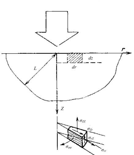
Consider a strongly absorbing elastically isotropic body, which at the initial moment of time is kept at zero temperature in a relaxed state and on whose surface an axisymmetric radiative flux is incident [1-14]. The en- ergy distribution in the laser beam cross section obeys the Gaussian
2
0exp 0 ,
I r I K r where 2
0 2 ;
K w
and is the radius of the irradiation region on the body surface. We assume that all the thermal and mechanical coefficients of the material do not depend on temperature, and the laser beam is absorbed directly on the irradiated surface. The nonlinear effects, as well as the energy loss by radiation and convection are neglected. Provided that the characteristic size of the beam is and the time of energy input is
w
,
wL 2
0
t L a (L is the characteris-tic size of the body, and a is the thermal conductivity of the material), the problem can be solved by using the half-space model (Figure 1).
dr dz L
Z
σrr σrZ σZr σZZ
[image:4.595.63.282.67.321.2]σφφ
Figure 1. CO2-laser radiation on the surface of solid body.
initial and boundary conditions:
2
T a T
t
(1)
0 2
0 0
1
exp ,
z I
T
K r
z K
(2)
, , 0
0, lim
, ,
, lim
, ,
.z r
T r z T r z t N T r z t M
(3)
Here, K is the thermal conductivity and is the re- flectivity of the material surface.
By applying to (1) the Hankel transform over r and the Laplace transform over t and using the initial and bound- ary conditions (3), we obtain:
20
4 0
0 0 0
1
, , e
4
e e
2 2
K
z z
I
T r z t J r
KK
z at z at
at at
d ,
(4)
where J0
r is the zero-order Bessel function and
x 1
x
;
x is the error function.The behavior of the temperature field on the surface of the body exposed to a laser beam is shown by the exam- ple of a quartz sample with a gold coating .
Figure 2 shows the surface temperature profiles calcu-
lated for several time points.
h10 nm2
However, if the exposure time satisfies the inequality
2
0 ,
w at L a
200
100
0 1 1 r,cm
T,˚C
Figure 2. Temperature profile de- pendence in time on the solid sur- face covered by gold.
0 2
0 0
0 0
, , 1
exp 4 exp d ,
2 T r z
I
J r K z
KK
(5)at the point r z 0, where the maximum temperature is reached. Then, expression (5) is simplified:
0,0,
π 0
1
.2 2
I w
T
K
(6) For comparison, Figures 3 and 4 show the calculated
distribution of the stationary temperature fields in gold- coated aluminum and quartz samples for different values of K0 at a given power level.
The analysis of expression (5) confirms the localiza- tion of the temperature field, the intensity of which de- creases sharply with increasing distance from the center of the irradiated region on the surface and deep inside the material.
The half-width of the intensity distribution of the laser beam is several times narrower than the half-width of the corresponding temperature profile on the irradiated sur- face, and the broadening of the latter is determined solely by the thermal conductivity of the material:
1 .
r K
If, during the laser exposure the melting point of the material is reached, then the optical surface is irreversi- bly deformed. By setting in (4) and equating the obtained expression for to the melting temperature Tm of the material, we can estimate the value
of the maximum laser intensity, which during the expo- sure time t0 leads to the melting of the surface layer:
0
r z
0,0T ,t
02 2π
, 1
пл
пл
T T T
T K
I f F
w
(7)
where
1
0
0
1 π 2arctg
2 2
T f F
F
2 then a stationary temperature field
can establish. In this case, the expression for the tem-
perature has the form:
1
0 2 r,cm
T,˚C
1 3
α
4 8 12 16
2 3
0 4 8 12 16T,˚C
δ
1 2
[image:5.595.66.281.85.231.2]3 1 2 3 4 5 z,cm
Figure 3. Temperature field distribution in the sample from Al covered by gold.
1
0 2 r,cm
T,˚C
1 3
α
2
0 400 600800 T,˚C
δ
1 2 1 2 3 4 5 z,cm
200 800
600
400
[image:5.595.330.518.86.248.2]200
Figure 4. Temperature field distributions in the sample from quartz covered by gold.
function, which depends on the dimensionless parameter (the Fourier number) 0
0 2.
at F
w
Thus, knowing the value of the temperature function at a given F0 (Figure 5), we can determine the maximum
intensity of the laser radiation, which leads to the melting of the optical surface, for any material and any beam geometry at known values of the parameters Tпл, K,
(Figure6).
From this discussion it follows that for 2
0 10
F
98.2% the value of T Tпл increases linearly with decreasing F0
and remains constant for 0 In particular, for an aluminum sample with a reflectance
I
3, ,5.
F
w
, the maximum intensity, leading to the melting of the surface, is 8.6 × 10⁷ W/cm2 with a pulse duration t
0 = 10−6 s and
is virtually independent of the parameter . If the dura- tion is t0 = 1 s, the values of the maximum intensity dif-
fer for different values of the parameter
( T Tпл W/cm2, and 0.2
cm, respectively сm), which is due to the mechanism of the material conductivity in the interaction process, resulting in a significant energy exchange be- tween neighboring areas of the irradiated body. Note that
w 5
1.6 10
;
I 0 ;5 6.5 10 5
;0.2 2.8 1
1;0.5
w
10-7
F0 fT
10-5
10-3 10-1 101
10-1
100
101
102
Figure 5. Temperature function ft dependence on Fo.
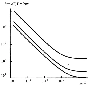
10-8
t0, C
Iσ= σT, Bm/cm2
10-6 10-4 10-2
104
105
106
107
1
2 3
Figure 6. Maximum intensity of the laser radiation dependence on laser pulse duration for Ko = 50, 8.2.
this solution is valid for describing the processes preced- ing the thermal breakdown of the material. The nonsta- tionary temperature field causes a stress in the irradiated body, which also changes with time. Let us now define thermal stresses in a solid body.
, ,T r z t
5.2. Thermoelastic Stresses
In the quasi-static formulation, the problem of deter- mining stresses in the half-space irradiated by an axi- symmetric flux leads to the equation
2 mT m 1 1
(8) with the initial conditions 0
0
0
t
t t
and bound-
ary conditions at which zz
r, 0,t
rz
r, 0,t
0.Here is the thermoelastic displacement potential
;
i
V i
, is the coefficient of linear expansion,
[image:5.595.330.517.270.451.2] [image:5.595.69.277.274.417.2]The solution of the problem is the sum of two fields of thermoelastic stresses: the fields ij, whose compo- nents of the stress tensor satisfy thermoelasticity equa- tions, but do not satisfy the boundary conditions, and the fields ij, whose stress components characterize the
temperature-free solution of the corresponding classical theory of elasticity and satisfy the boundary conditions of the thermoelastic problem. After necessary transfor- mations, we obtain the desired stress field:
2 0 41 1 0
0
1 0
0 1
e
1 2 1 e
2 2
2 e t d
K rr
z
z
C J r P J r Q
r z
J r J r z R
r
z
J r z J r
r ;
2 0 41 0 1
0 0 0 1 0 1 1 e 1 2 2 e 1 2 2 K z z С
e d ;
J r J r P
r
J r Q
z
J r J r R
r z
J r J r t
r
(9)
2 0 2 0 4 1 0 0 3 4 1 1 0 2 2 e1 e e d ;
e
e 1 e
K zz z z K rz z z
C J r
P z R zt
C J r
z t zR S
d
Here
0 1 0 1 1 1 aI G C KK (G is the displacement modulus)
2 2 0 2 2 4
1 e 2 e 2
2 2 2
1 2 e 2
4 2 1 2 e 4 2 e ; 2 π t z z z z z at at
z a t z a t
P t
at at
z at z a t
Q
a at
z at a
z a t t
at a
23 2
1 e ;
2 π
2 e 2
4 2
2 e 2 .
4 2 a t z z t t R at a a
z at z at
S
a at
z at z at
a at
The expressions obtained show the variation of the stress field of the irradiated body during exposure to la- ser radiation. The maximum values of the radial and circumferential stresses are at a point r = 0 on the surface, where they are equal to each other, and can be written in the form:
1 2 1
0
0 0
0 2 1
0
1 3 5 1
0,0, ; 2; ;
2 2 4
3 π
2 1
1
1 4 2
π
1 1 3 1
π ;1; ;
2 2 4
π
ii t C F K at
a at K
t r
K at a a K F K at at (10)
[2 1F
, , ,
is the hypergeometric function]. Expression (10) allows one to evaluate the maximum laser intensity т leading during the irradiation timet0 to the achievement of the yield strength of the material,
and to determine the maximum permissible duration of the laser pulse, corresponding to the given intensity. It is known that at intensities greater than the limit, plastic deformations arise in the surface layer, and after the ter- mination of the laser pulse inevitable there appear resid- ual stresses. Multiple repetition of the described process leads to a rapid destruction of the optical surface.
,
I
d ;
[image:6.595.336.511.87.176.2]
Figure 6 shows the dependence of the maximum laser
intensity on the pulse duration for three values of the pa- rameter K0 for a polished aluminum sample. Comparing
the dependence obtained with the dependence
,T Tпл 0
I f t one can see that the maximum intensities, leading to a plastic yield of the material, are by 1.5… 2 orders of magnitude lower than the values corresponding to the melting of the material. In the case of CW expo- sure a stationary stress field can arise, which for the half- space has the form
0 0 21 1 0
0 2 0 0 0 0 2 2 0 2
0 1 1 0
0
π
1 1
,0, ; 2; ;
2 2 2
1
,0, π exp
2 2
4 1
π ;2; .
! 1 2 2
rr m m K I E r F KK
I E K r
r K
KK
K r r
K F K r
Here 1 1F
, ,
is the degenerate hypergeometricfunction and E is Young’s modulus.
The components of the stress tensor rr and
on the metal surface as a function of distance from the center of the irradiated region are shown in Figure 7.
The change in the sign of the component at a dis- tance 0 seems interesting. This behavior of the
stress field can lead to cracking of the material in the ir- radiation region and to its subsequent chipping.
0
r
Let us analyze now the other two components of the stress field in a solid body, arising during its exposure to a high-power light of finite duration, namely, zz and
.
rz
Of most interest is the consideration of the behav- ior of the component zz, because the component rz
due to the axial symmetry of the problem everywhere on the axis is zero and zz has a maximum at point z0 > 0.
Figure 8 shows the dependence of the stress field
component zzat the axis
r0
of the aluminumsample during the exposure to laser radiation with inten-
sity
2
0exp 0
I K r on the pulse duration t0. The feature
0 r, cm
σ, k2c/cm2
1 2 3
-75 -50 -25 0
4 25
σrr
[image:7.595.327.540.330.421.2]σφφ
Figure 7. The components of the stress ten-sor rr and on the metal surface of Al as a function of distance from the center of the irradiated region
0 z, cm
σzz, k2c/cm2
0.25 0.5 0.75 10
20 30 40
1
σφφ
2 3
[image:7.595.87.255.335.494.2]4
Figure 8. The dependence of the stress field component σzz at the axis (r = 0) of the alu-minum sample during the exposure to laser radiation with intensity I0 exp(−K0r2) on the
pulse duration t0.
of the behavior in the component zz is the fact that as
the exposure time decreases the maximum stress at point
z0 passes through a maximum, and the coordinates de-
creases monotonically, approaching the surface. By equa- ting the expression for the component zzat point z0 to
the ultimate tensile strength of the metal, one can esti- mate the intensities at which the coating starts sagging during the exposure. Thus, the destruction of the optical surface by laser radiation can occur at intensities much lower than those required for its melting.
5.3. Surface Deformation
Let us determine the value of the displacement of the solid-body surface due to the impact of laser radiation. Displacement of the body surface can be represented as the sum of the derivatives in the coordinates of the ther- moelastic displacement potential and Love’ function. The expression for the normal surface displacement that ma- tches the temperature distribution has the form
2 0
0 0 4
0 2
0
2
1
,0, 1
1 e
2
exp d .
π
K
aI V r t
KK
J r t at t
a
t a t
a
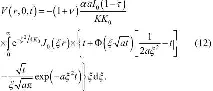
(12)The displacement is negative, because the Z-axis is directed into the solid body. Profiles of the optical sur- faces of various materials, deformed by the laser beam, are calculated at t0 = 1 s, K0 = 2 and P = 1 kW and are
shown in Figure9.
The graph shows that the minimum deformation
0 r, cm
V, mkm
2 0.2
0.4
4 0.6
1 3
[image:7.595.85.252.336.670.2]4 2 5
Figure 9. Profiles of the optical surfaces of various materials, deformed by the laser beam, are calculated at t0 = 1 s, K0 = 2
[image:7.595.369.479.513.674.2]corresponds to a gold-coated quartz sample. This is ex- plained by a slow increase in the material heating region due to the low thermal conductivity of quartz, and by the low value of its thermal expansion coefficient. However, the temperature of the surface of the quartz—gold sam- ple is two orders of magnitude higher than the tempera- ture of the copper sample. Equally significant is the de- pendence of the deformation of the irradiated surface on the energy distribution in the laser beam cross section.
Figure10 shows the deformation profiles of the surface
of the nickel sample at different K0.
Consider the dependence of the surface deformation on the time of its irradiation. To do this, if r = 0 in (12) and the previously adopted notation is used, we obtain
0 0
0
0
1
0, 0, 1
1 2
4 1 2 0.25ln
1 2 I
V F
KK
R ,
F R R
R
(13)
where
0
0
2 . 1 8
F R
F
Thus, knowing the necessary parameters
, , ,K K a0,
, one can determine the maximum defor-mation of the surface in the center of the irradiated re- gion for any material and any exposure durations.
Note the following characteristics of the deformation process resulting from the consideration of the expres- sions obtained:
1) The process is local, and with decreasing exposure time the half-width of the deformation profile, exceeding the corresponding value of the laser beam for large t0,
approaches the half-width of the energy distribution in the beam cross section, which causes deformation of the irradiated surface.
2) The value of the deformation increases rapidly at
0 V, mkm
2 0.5
1 1
3 2
r, cm
1.0
Figure 10. The deformation profiles of the surface of the nickel sample at different K0 =
50,8,2. P = 1 kW, t0 = 0,25c.
small values of the Fourier transform F0 and the rate of
its increase is proportional to the intensity of the incident flux. When 0 , the rate of change in the defor-
mation decreases and the displacement of the surface continues to vary logarithmically slowly. The stage of the elastic behavior of the material is characterized by com- plete recovery of the initial state of the surface when ter- minating the laser action. However, in some cases, the deformations of the optical surface become inadmissible. Accounting for deformation is crucial for such laser sys- tems as the quasi-optical transmission lines, telescopes, unstable resonators, and focusing systems.
3 4
F
The maximum of laser radiation can be estimated by equating V in (13) to the Vad, corresponding to the ma-
ximum admissible deformation of the surface, at which additional losses exceed some value fixed for each sys- tem
доп
0 доп
0 ,
1 1
V V V
KK V
I f F
(14)
where
доп
0 доп
0 ,
1 1
V V V
KK V
I f F
is the the dis-
placement function.
Thus, knowing the values of the function f FV
0 ,onecan estimate the maximum intensity, resulting in admis- sible deformations of the optical surface of any material that obeys Hooke’s law. The dependence of the displace- ment on the dimensionless parameter F0 is shown in Fig-
ure 11. If F01 the rate of a decrease in the function
0 Vf F varies significantly, due to the saturation of the process of heat exchange by the material conductivity. The further slow drop in the displacement function is due to the increase in the value of the surface displacement from the effective heating region, the volume of which increases with F0.
Consider the behavior of the maximum intensities
доп т дп as functions of the laser pulse du-
ration 0for an aluminum sample (Figure 12), calcu-
lated for the beam with cm at
,
V V
I
t
, T T
I I
1
w Tдп 660 C,
10-7 F0
fV
10-5 10-3 10-1 101
10-1
101
103
105
10-7 t 0,c
10-5 10-3 10-1101
102
I,Bm/cm2
α
103
104
105
106
107
108
10-7 10-5 10-3 10-1 t 0,c
δ
106
104
102
100
1
2
3
1 2 3
[image:9.595.60.285.87.220.2]E/S, д*/cm2
Figure 12. The maximum intensities de- pendences on the laser pulse duration t0 for an aluminum
sam-ple for the beam with w = 1 cm at kg/cm2.
доп, т, дп
V V T T
I I I
660 C,
т 5 1
дп
T 02
2 т 5 10
kg/cm2 (the wavelength of the incident ra-
diation is 10.6µm). For pulse durations 3
0 2 10
t
and the given parameters of т and доп, the main
process, which limits the maximum value of the laser intensity, is the elastic deformation of the reflecting sur- face. With a pulse duration less than this, the transition of the material to the inelastic region becomes crucial, which is due the stresses (caused by irradiation) above its yield strength. It is however important to note that the pulse duration s for aluminum depends on the parameter 0
V
3
2 10
0
t
K of the incident beam and significantly decreases with its increase. Thus, for example, at
cm the value of the pulse duration 0, for which
the surface deformations should be taken into account, is s. Insignificance of the process of the reflecting surface deformation at low laser pulse durations is ex- plained by the smallness of the effective heating of the material.
0.2 w
5
3 10
t
However, it should be noted that these estimates are valid for ideal surfaces in a vacuum, because the pres- ence of air and slight contamination of the irradiated surface can lead to the breakdown of the gas near the surface and, consequently, to its destruction at laser in- tensities that are less than the estimated ones.
6. POROUS STRUCTURES IN HIGH
POWER OPTICS
The feasibility of using structures with open porosity for cooling heat-stressed laser mirrors was justified for the first time theoretically and experimentally in [21]. An increase in the optical damage threshold of laser reflec- tors based on porous structures was provided by a “mi- nimum” thickness of the separating layer (tens of mi- crons), by the heat transfer growth via an increase in the coolant circulation velocity pumped through the structure and by the effect of the significant development of the surface [21-26]. We have shown experimentally that the placement of special porous structures in made it possi- ble to increase (by ~ 9 times) the effective coefficient of
convective heat exchange and to reach ~ 22 W/cm2 × deg.
The test results of water-cooled laser mirrors that are based on the structures with open porosity first indicated the possibility of removal of high heat flows at low val- ues of the mirror surface deformations. The maximum density of the heat flow being removed, which does not lead to destruction, is max kW/cm2, and at q = 2
kW/cm2 the 10.6 µm/20, where q 8 λ value of thermal
deformation was ~λ/20 µm. A further increase in the op- tical damage threshold of cooled mirror surfaces can be achieved by optimizing the parameters of the porous structure, the appropriate choice of the coolant and the rational design of its inlet and outlet. The development of such “optimal” laser reflectors requires a detailed study of heat and mass transfer in porous structures, which are currently insufficiently studied. Let us consider some aspects of this problem.
6.1. Temperature Field
The temperature fields in the porous structures are cal- culated in the one-dimensional formulation under the fol- lowing assumptions: the incident radiation is uniformly distributed over the irradiated surface; the thickness of the porous layer is much greater than the depth of heating, which makes it infinitely large and allows consideration of the half-space model; and the temperature and velocity of the flow through the thick- ness of the porous layer is constant.
Then the heat transfer equation, which describes the temperature distribution over the thickness of the porous layer, can be written as
22
d
, d
s
V T
h t
S t t
x
(15)where x is the coordinate; t, tT is the temperature material
(skeleton) of the porous structure and the coolant, re- spectively; hs is the heat transfer coefficient between the
material structure and coolant; is the skeleton ther- mal conductivity along the axis x; and SV is heat transfer
surface per unit volume. Equation (1) can be written in the dimensionless form:
2 2
d
1 ,
dx N
(16) where t t xT; x ds and NNu N are the di-
mensionless temperature, coordinates and parameters, respectively; dsis the average particle diameter in the
structure; Nu h ds s is the modified Nusselt number,
which characterizes the ratio of convective to conductive heat transfer across the skeleton boundary; and
V s
N S d is the dimensionless parameter characterizing the structure.
the form:
0;d d Nu ; 1,
x x qx (17)
where q q h t
s T
is the dimensionless heat flux den-sity; q is the heat flux density transmitted through the separating layer.
Solution to equation) with the boundary conditions (17) has the form:
x 1 q Nu Nexp
Nx
. (18)
It follows from (18) that the rate of temperature de- crease over the thickness of the porous structure is de- termined by the parameter N .
We write down some relations required to calculate the thermal characteristics of laser reflectors. The tempera- ture of the separation layer at the interface with a porous substrate
x0
has the form:p 1 q Nu N
. (19)
The maximum heat flux density, removed from the re- flector due to convective cooling, follows from the con- dition of equality of the coolant p and the boiling point s at appropriate pressure
p s
and has the form:
max s 1 N
q N u. (20)
The degree of heat transfer in a porous structure as a result of the flow circulation and the surface develop- ment is determined by the coefficient Kин, which char-
acterizes the ratio of the amount of heat removed by the coolant in the structure under consideration, to the amount of heat that would be removed directly from the cooling surface of the separation layer by the coolant when it flows in a Δ channel of depth
ин x 0 T ,
K q h t t
where is the coefficient of convective heat transfer in the coolant flow in a slot gap of size Δ. For example, for the turbulent regime of the coolant flow the Nusselt num- ber
h
Nu has the form
0.8 0.4
Nu0.023Re Pr ,
where Re, Pr are the Reynolds and Prandtl numbers. Let us introduce the coefficient of heat transfer due to the flow turbulence KT h hs , where hs is calculated
from the condition that the flow of coolant circulating through the reflector is constant. Then, Kин depending
on the structure type and parameters and on the thermo- physical properties of the coolant is calculated as fol- lows:
ин 0 T,
K K K (21) where K0q h ts
x0tT
N Nu
1 2 is the coeffi-cient of ribbing of the cooled surface of the separation layer.
Equation (18) allows one to find the depth of the struc- ture heating that defines the minimum possible thickness of the porous layer, conventionally assuming that the heating ends at the coordinates x ds where the
skeleton and the coolant temperatures differ by 1%:
1 21 2ln102 Nu .
N q N
(22)
In the case of removal of the maximum heat flux den- sities, the depth of heating is
1 2 2
max N ln10 s 1 .
(23) Thus, relations (18) - (23) allow one to calculate the temperature fields and thermal characteristics of the cooled laser reflectors. In combination with the expres- sions describing the flow hydrodynamics, they are the basis for optimizing the parameters of porous structures, ensuring minimal thermal deformations of mirror sur- faces or, if necessary, the maximum heat flux, removed in the case of convective cooling.
6.2. Convective Heat Transfer
The regime of the coolant flow in porous materials, which are of interest for high-power optics, is a transition between laminar and turbulent regimes; in this case, the calculation of the heat transfer coefficient between the skeleton and the coolant is very difficult despite numer- ous experimental data. The lack of a unified approach to processing of the experimental results and the inability to accurately determine such important characteristics as the SV, ds etc. make the calculation of heat transfer of
liquid drops in various types of porous structures with geometrical parameters that vary widely. Therefore, these equations can only be recommended as a first approxi- mation to calculate the volumetric heat transfer coeffi- cient in structures that are identical to the tested ones, and to gas coolants. It is generally accepted that the cri- terion equation of the interporous convective heat trans- fer for gases and droplets has the form:
Nuc Re Pr n, (24) where c and n are the constants depending only on the structural characteristics of the porous material.
Based on the experimental data of papers we analyzed the dependences of c and n on the structural characteris- tics of porous materials for which the latter are quite au- thentically known; as a result, we found that c and n de- pend mainly on the bulk porosity V. Thus, relation for
the dimensionless Nusselt number with account for cor- relation expressions с(ΠV) and n(ΠV) allows one to cal-
culate the coefficient of convective heat transfer in a po-
rous material.
6.3. Hydrodynamics of a Single-Phase Flow
The temperature field and thermal deformation of the reflector are largely determined by the discharge of the coolant pumped through a porous layer, which depends on the hydrodynamic characteristics and conditions of the coolant inlet and outlet. Hydrodynamic characteris- tics of a single-phase fluid flow in porous materials, mainly in the region were studied in many ex- perimental works. The expressions proposed by different authors can be used to calculate the hydrodynamics of the flow in materials that has an identical structure to the samples studied.
0.5,
V
In general, the hydrodynamics of the flow in porous materials is described by the modified Darcy’s equation (Dupuit – Reynolds – Forchheimer):
2
d
, d
p
u u
x
(25) where p is the flow pressure; u is the filtration rate, equal to the ratio of the specific coolant discharge G to the density ρ; and β are the viscous and inertial is coefficient of dynamic μ resistance coefficients, respectively; and viscosity of the coolant.
From Equation (25) we obtain the equation for the co- efficient of friction, Cf, in the form
2 Re 2,
f
С (26) where 2 d d
2 ; Ref
C p x G G (the char- acteristic size β/α).
Practical use of relation (26) for the calculation of the hydrodynamics of the flow in different types of porous materials, whose structural characteristics vary widely, is hampered by lack of information about the coefficients α
and β, which are usually determined experimentally. Well known a slightly different approach to the calcu- lation of Cf: as a characteristic size they used K ,
where K is the permeability coefficient, characterizing the hydrodynamics of the flow according to Darcy’s law
Re K G K
, then
2 1 Re .
f K
C c c (27) The relationship parameters α and β between the coef- ficients c and K can be represented as 1 K and
c K
.
Parameter c is a universal constant for identical porous structures. For example, for all the materials made of metal powders with spherical or close-to-spherical parti- cles we have , and for materials made of pow- ders of arbitrary shape we have . Thus, in the future when calculating the hydraulic characteris- tics of the structures we assume , although in
our case this provides a somewhat higher value of the coefficient of friction.
0.55 c
0.45 c 0.566
0.55 c
Research conducted with fibrous materials, foams and structures of the layers of particles of arbitrary shape has shown that the parameter c for these materials is rela- tively small. This is explained by the fact that c, charac- terizing the fraction of inertial losses, depends largely on the nature of the wake formed behind solid particles due to the flow, and the wake depends on the type of porous structure.
The presence of the free ends (further turbulizing the flow) in metal-fibrous structures increases c; therefore, for a relatively short fibers, l/d = 50 - 100, с≈ 0,132.
The permeability coefficient K, which is a structural characteristic of a porous material, does not depend on the flow regime and is determined experimentally from Darcy’s law. In connection with the development of works in the field of heat pipes, many experimental data are currently available to determine K for powder and metal fibrous structures. According to our experimental data, the relation of the permeability coefficient for metal fibrous structures with bulk porosity has the form:
,
m V
K A (28) where A and m are the coefficients depending on the relative length of the fibers l/d. Similar expressions can be obtained for powder materials.
In addition, the permeability coefficient is calculated from the known Carman-Kozeny relation:
23 2 1 3
V s V V 5 V,
K d S (29) where is a constant depending on the structure.
Expressions (27) - (29) were used to determine the hy- draulic characteristics of the power optics elements, made of porous materials based on metal powders and metal fibrous structures.
6.4. Effect of the Coolant Inlet and Outlet Conditions on the Hydraulic
Characteristics
Usually, in cooled laser reflectors the coolant is sup- plied to and removed from the porous structure through evenly distributed alternating channels, which are made in the form of slots or holes on the cooling surface. With a slotted inlet, a more uniform velocity field of the cool- ant and a minimum differential pressure required for its pumping are provided. In the case of inlets and outlets in the form of alternating holes we may deal with a signifi- cant non-uniformity of the velocity field in calculating the flow in radial directions. This leads to additional pressure drops in the circulation of the coolant, which are considered by the coefficient Kг; in this case, the total
г,
P pK
(30) where Δр is the pressure in the case of a uniform velocity field.
Under the assumption of uniform injection (outflow) of the coolant in the radial directions in the regions of supply (outlet) restricted by the region r0 r s 2 (s is a step between alternating holes, r0 is the radius of the
hole), the coefficient Kг, characterizing the influence of
collector effects on hydraulic resistance during the mo- tion of the fluid in a porous layer, can be written as:
г π 2 1
1 1 π ln
.
F K
s n a
cG a n s K a
K cv
(31)
Here G is the mass flow rate of the coolant, F is the area of the exposed surface, n is the number of channels for the supply (outlet) of the coolant, and a2r0 s is a relative spacing between the holes. One can see from Equation (31) that Kг depends both on the geometric
characteristics of the supply and removal of the coolant (on a) and on G; with increasing a and G, the coefficient
Kг increases. Thus, the coefficient Kг is characterized by
design excellence of the inlet and outlet system of the mirror coolant.
With the known Kг the total pressure drop in the
po-rous layer is calculated by the formula (30), taking into account the expression for calculating р:
1
p v s a K cv K
, (32)
where v = Gs/(ρFΔ) is the coolant filtration rate.
6.5. Thermal Conductivity
As for the problems of cooling of power optics ele- ments, of interest is to study the thermal conductivity of a porous material skeleton without account for the ther- mal conductivity of the coolant. Taking into account the summarized the results of numerous experimental studies of thermal conductivity of materials of various structures and showed that the effective thermal conductivity de- pends not only on the volume porosity, but also on such factors as the sintering behavior of the material, the size and shape of the primary particles, pressing and sintering technologies, etc., which leads to a large scatter in the data and makes it difficult to generalize the results. Prac- tical data are summarized in the form of the dependence
(ПV) for the samples, manufactured using the single
technology and the same type of material. Analysis of experimental results shows that for the calculation of a wide range of porous powder materials can be based on the Odolevsky equation:
к 1 V 1
V , (33) where λк is the thermal conductivity of a compact mate-
rial.
Effective thermal conductivity of metal fibrous felt structures may have a considerable anisotropy depending on the direction of the fibers in the felt. Thus, on the ba- sis of is generalized by the relations:
к 1 V exp
V , (34a)
2к 1 V
, (34b) where is the effective thermal conductivity in the direction parallel to (34a) and perpendicular (34b) to the felt-making plane. In the latter case one can also use the expression
3к 1 V
. (35)
Expressions (34b) and (35) satisfactorily approximate the experimental data and can be used in the determina- tion of the thermal characteristics of cooled laser mirrors, made of metal fibrous structures. In this case, expression (34b) describes the upper limit of the experimental data (an optimistic estimate), and (35)—the lower (a pessimi- stic estimate).
6.6. Estimate of the Thermal Deformation
In general, thermal deformations of a mirror are calcu- lated by using the temperature field of the separating layer and the porous base and the known conditions of their attachment. The exact solution of this problem of thermal strength under real conditions of the reflector ex- posure is very difficult.
To estimate the low distortions of the optical surface, which are characteristic of deformation of power-optics elements, one can make the assumption of free expansion of the porous base and the separating layer according to the temperature fields. Then, the thermal deformation of the mirror surface W is the sum of extensions of the separating and porous layers:
p p 1 2 0
0
1 2
1 ,
T
n T s
W t
t qd N
(36)
where αp and αn are the temperature coefficients of linear
expansion of the separating and porous layers, respec- tively; i t ti T is the dimensionless temperature; t0 is
the coolant temperature at the inlet of the reflector; and t1
and t2 are the temperatures of the outer and inner surfaces
of the separating layer, respectively.
the form
,
T T
t qF GC
where GT is the heat capacity of the coolant. 6.7. Results of Thermal Characteristics
Calculations
The above-derived expressions describing the proc- esses of heat and mass transfer in porous structures, were used to calculate the characteristics of cooled laser mir- rors with the coolant inlet and outlet system in the form of uniformly (with a step s) alternating holes; the distribu- tion of the heat load on the surface of the reflector was assumed uniform.
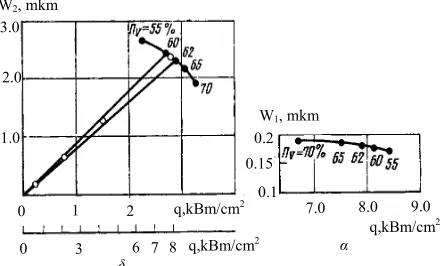
Figure 13 shows the qualitative dependence of the
deformation on the maximum density of the heat flow being removed (the constant ПV at a constant ds) for two
selected regions of the reflector, corresponding to the regions of injection W1(qmax) and outflow W2(qmax) of the
coolant. Varying the average grain size ds (or the diame-
ter of the fiber), we can construct a family of curves, characterized by a constant value of ds and variable po-
rosity ПV, for reflectors with the same type of capillary
structure. The curves are plotted at a constant pressure drop and by taking into account the coolant heating in the porous layer; the temperature of the coolant at the inlet temperature was assumed equal to the temperature of the final finishing of the mirror. The deformation of the optical surface in the coolant outflow region obeys
W2 > W1. Crucial to the selection of the structural char-
acteristics of the porous material is curve 2, and the dif- ference between curves 1 and 2 characterizes the degree of the cooling system perfection. The curves are the en- velopes of the working thermal deformation characteris- tics of a family of reflectors with this type of structure. Performance characteristic of the reflector with a given porosity structure ПV is obtained by connecting the
q W
0 qnp2 qnp1 q
q
2 c
a W
1
Πv
apt v1
apt v2
b
Figure 13. Qualitative dependence of the thermal deformation on the maximum heat flux density removed from two regions of the reflector, corresponding to the region of the coolant in-jection (1) and outflow (2).
straight line from point C with the origin of the coordi- nates. Point C corresponds to the maximum heat flow, removed due to convective cooling, and the line segment OC is a dependence of thermal deformations of the mir- ror surface on the heat load. In general, curve 2 has two main points: point A corresponding to optimal porosity
1 which facilitates removal of the maximum heat flux
density for the selected grain size, coolant pressure drop, and coolant supply and removal conditions; and point B (the point of tangency of curve 2 with the straight line from the origin of the coordinates) corresponding to the porosity 2
,
opt V
opt V
, for which in the porous structure the op- timal thermal distortions of the mirror surface are real- ized.
The choice of material and the basic parameters of the structure (ds, ПV) must be based on a comparison of a
[image:13.595.310.533.328.660.2]family of curves 2 with possibilities of obtaining the de- sired porous structures and separating layers.
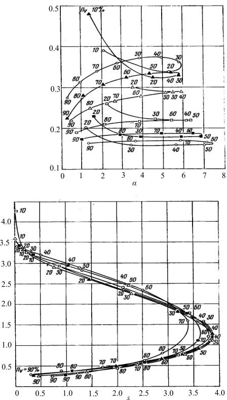
Figures 14 and 15 present the results of numerical cal-
0 0.1
1 2 3 4 5 6 7 8 9 10 11 12 13 0.2
0.3 0.4
δ α
4.5
4.0
3.0
2.0
1.0
1.0 3.5
2.5
1.5
0.5
[image:13.595.60.282.542.687.2]0 0.5 1.5 2.0 2.5 3.0 3.5 4.0
0.1
2 3 4 5 6 7 8
0.2 0.3 0.4
δ α
4.0
3.0
2.0
1.0
1.0 3.5
2.5
1.5
0.5
0 0.5 1.5 2.0 2.5 3.0 3.5 4.0
1 0 0.5
Figure 15. Nomograms of thermal deformation characteristics of a family of water-cooled reflectors based on porous struc- tures made of copper (a, b) and molybdenum (c, d) felt: the re- gion of the coolant injection (a, c) and region of the coolant outflow (b, d).
culations of thermal deformation characteristics of a family of water-cooled reflectors with porous structures made of the widely used copper powders (Figures14(a)
and (b)) and molybdenum powders (Figures14(c) and (d)),
illustrating the capabilities of the method. The average grain size and bulk porosity varied between 20 ≤ds ≤
200 µm and 0, 1 ≤ПV≤ 0,9.
One can see from Fig. 14 that the maximum heat flux densities are as follows: in the region of the coolant inlet qпр1 = 12.8 kW/cm2, in the region of the coolant outlet
qпр2 = 3.75 kW/cm2, with W1 = 0.1 - 0.4 µm, and W2 =
0.4 - 3.5 µm. In the region of the maximum heat flux density W2 = 1.5 - 2 µm, which is in most cases much
higher than the maximum allowable deformation of the reflectors for CO2 lasers.
With the increase in coolant flow (Figure 14(b)) W2
can be dramatically reduced by using the materials with high bulk porosity (0.7 - 0.8) and the transition to a lar- ger grain size. In this case, qmах = 2 kW/cm2 at W = 0.5
µm. Powder-material structures with ПV > 0,75 for the
power optics are very difficult to produce. With a de- crease in porosity to the real values (~0.6) the heat flux densities being removed will be ~ 1.4 kW/cm2 at a 0.5
µm deformation. Note that increasing the coolant flow rate is also achieved through rational design of the cool- ant inlet and outlet system, providing a more uniform distribution of the coolant along the cooling surface.
One can see from Figures14(c) and (d) that the use of
porous molybdenum allows an approximately four-fold decrease in the level of thermal deformations of mirror surfaces in both the first and second regions; in this case qпр somewhat decreases: qпр1 = 7,8 kW/cm2, (qпр2 = 2,8
kW/cm2). For this structure (
Figure14(c)) in the imple-
mentation of the maximum removed flows the arising thermal deformations are below the characteristic optical damage thresholds of the reflectors for CO2 lasers. For
example, a structure with ΠV = 83% иds = 20 µm facili-
tates the removal of qmax = 2.8 kW/cm2 at W = 0.45 µm.
With increasing the coolant flow W2 1 (Figure
14(b)), qmax decreases. In this region the level of heat
flows to be removed can be increased by the use of ma- terials with the larger size of the particles; for example, the molybdenum powder structure with ΠV = 83% иds =
20 µm facilitates the removal of qmax = 2.1 kW/cm2 at W
= 0.23 µm.
W
Figure15 shows the thermal deformation characteris-
tics of the reflectors with porous structures made of cop- per (Figures 15(a) and (b)) and molybdenum (Figures 15(c) and (d)) felt. One can see from Figures15(a) and (c) that the transition to metal fibrous structures leads to
a significant (~1.7) decrease in qпр, which is associated
with a decrease in the effective thermal conductivity of these structures compared to powder structures.
In regions of the coolant outflow (Figures 15(b) and (d)) the maximum heat flux densities are on the same
level as for the mirrors with powder structures; however, an increase in the coolant flow leads to a strong depend- ence of W on ПV and to less sensitivity to the diameter of
the initial fibers. Deformations corresponding q# are ap- proximately two times lower compared to the powder structures: for copper and molybdenum reflectors W = 1.2 and 0.3 µm at qпр = 3,9 kW/cm2 and qпр = 2.6
kW/cm2, respectively.
For mirrors with a copper fiber structure the heat flux densities, which can be realized with W = λ/20 (where λ
= 10.6 µm), of 2.4 kW/cm2, are 2.4 kW/cm2, which ex-
ceeds the corresponding level of qmax for powder materi-
[image:14.595.60.284.83.477.2]