Performance Analysis on Output SINR of Robust
Two-Stage Beamforming
Tsui-Tsai Lin1, Fuh-Hsin Hwang2, Juinn-Horng Deng3
1
Department of Electronic Engineering, National United University, Miaoli, Taiwan; 2Department of Optoelectronics and Communi-cation Engineering, National Kaohsiung Normal University, Kaohsiung, Taiwan; 3Department of Communication Engineering, Yuan Ze University, Taoyuan, Taiwan.
Email: [email protected]
Received October 30th, 2010; revised January 3rd, 2011; accepted January 4th, 2011
ABSTRACT
In this paper, we present a theoretical analysis of the output signal-to-interference-plus-noise ratio (SINR) for eigen-space beamformers so as to investigate the performance degradation caused by large pointing errors. For the sake of reducing such performance loss, a robust scheme, which consists of two cascaded signal processors, is proposed for adaptive beamformers. In the first stage, an algorithm possessing time efficiency is developed to adjust the direc-tion-of-arrival (DOA) estimate of the desired source. Based the achieved DOA estimate, the second stage provides an eigenspace beamformer combined with the spatial derivative constraints (SDC) to further mitigate the cancellation of the desired signal. Analysis and numerical results have been conducted to verify that the proposed scheme yields a bet-ter robustness against pointing errors than the conventional approaches.
Keywords: Beamforming, Large Pointing Error, Output Signal-To-Interference-Plus-Noise Ratio (SINR), Eigenspace Beamformer, Two-Stage
1. Introduction
It is well known that conventional adaptive beamfomers are effective in suppressing strong interferers as long as the error in the steering vector due to pointing inaccuracy is small [1]. In the presence of steering vector errors, these beamformers exhibit severe degradation in per-formance in that the output signal-to-interference-plus- noise ratio (SINR) drops dramatically. Remedies have been proposed to lessen the effect of desired signal can-cellation [2]. In particular, the linearly constrained mini- mum variance (LCMV) beamformer uses the spatial de-rivative constraints (SDC) to alleviate sensitivity to the pointing errors by means of a flatter main-lobe response [3,4]. Unfortunately, this in turn results in large sidelobes and leads to a loss in array gain against noise. Further-more, the decrement in the beamwidth as the input sig-nal-to-noise ratio (SNR) increases makes it poor in inter-ference suppression due to the directional mismatch [5]. In the extreme case of high input SNR, since the desired signal may fall outside the main-lobe region, the SDC beamformer would null out not only the interference but also the desired signal. In [6], a robust scheme employs the leaky elimination constraint and the interference null
constraint to preserve the desired signal and to keep nice interference nulling simultaneously. This method needs to identify the interference subspace for the sake of re-storing the interference correlation matrix. However, in the presence of weak interference, it is difficult to extract the interference subspace from the received data. Chang and Yeh [7] proposed the eigenspace beamformer, in which the weight vector is constrained within the signal sub-space of the received data correlation matrix. In spite of success in dealing with a moderate pointing error, this approach cannot completely remove the interference and the residual interference impairs the system performance, especially for the weak interference (low signal-to-inter- ference ratio, SIR). To mitigate the effect of large point errors, an iterative searching method [8] is considered for constructing the correct constraint vector before beam-forming. Its low convergence behavior because of a large pointing error becomes crucial in practice. This approach, at the worst, breaks down when the desired signal falls outside the main-beam region in the case of high input SNR and/or a large antenna array.
scheme for adaptive beamformer is proposed [9]. The design of this beamformer involves the following proce-dure. First, an accuracy direction-of-arrival (DOA) esti-mate is determined from a few angles-of-interest in ac-cordance with the fact that the output power of the beam- former decreases with the increment in the pointing error. By exploiting the refined resultant, an eigenspace beam-former incorporating with the SDC is used to further mitigate the aggregate impacts due to the pointing errors. A closed-form approximate SINR expression is given to indicate the achievable performance improvement. Nu-merical results then confirm the efficacy of the proposed robust method and corroborate the predicted SINR re-sults.
The remainder of the paper is organized as follows: Section 2 reviews the array data model and presents the SINR performance analysis of the eigenspace beam-former. The proposed two-stage beamformer and its per-formance analysis are provided in Section 3. Simulation results and conclusion remarks are given in Sections 4 and 5, respectively.
The notations used in this paper follow the usually conventional-bold capital letters denoting vectors and matrices. I is an identity matrix with a proper dimen-sion, diag v
is a diagonal matrix with its entries formed by v,
T and
H are transpose and com-plex conjugate transpose of
. Also, Re
, E
, and are used to denote real part, ensemble average, and absolute operators, respectively.2. Preliminary
The scenario considered herein involves a single desired source and K1 uncorrelated interfering sources, all assumed to be narrowband with the same center fre-quency. These sources are in the far field of a uniform linear array consisting of M identical elements spaced by half a wavelength. Adopting the complex envelope notation, the array data obtained at a certain sampling instant can be put in the M1 vector form:
1
.
K
k k k
n s n n
x a n (1) The random scalars sk
n for k1, 2,,Krepre-sent the signals with power 2
k
. The M1 vector
1,ejsin, ,ej M 1sinT M
a i s t h e a r r a y
steering vector, in which is the physical angle meas-ured with respect to the broadside of the array. Finally, the vector n
n is additive white Gaussian noise with power n2I. Without loss of generality, suppose s n1
is the desired signal.
The LCMV beamformer, which minimizes the array output power subject to a unit constraint on the presumed
vector, is widely used to preserve the desired signal and keep interference nulling simultaneously. Mathematically speaking, the optimal weight can be obtained by [3]:
1 1
,
H
s s s
w R a a R a (2) where a
s is the steering vector associated with thelook direction s, and R is an MM received data
correlation matrix given by
2
21
.
K
H H
k k k n k
E n n
R x x a a I (3)
According to the orthogonality between the signal and noise subspaces, the eigenspace technique can be used to mitigate the effect of desired signal cancellation and its corresponding weight vector is given by
1 1
,
H s s s
H H
s s s s s
w E E w
E E R a a R a (4)
where the MK matrix Es is formed by the K
principal eigenvectors of R. Under proper conditions, the eigenspace beamformer is found to achieve high output SINR as long as the pointing error
s 1
isnegligible. Unfortunately, in the case of the large point-ing error and/or high input SNR, its performance is lim-ited mostly by the residual interference buried in the beamformer output.
To gain further insights, we will describe the effect of the residual interference caused by pointing inaccuracy. For a manageable analysis, the scenario is simplified into that involving a desired source with power 2
1 1
and an interferer with power 2
2
only, i.e., K2. Thus the received data correlation matrix can be rewritten as
2
21 1 2 2 2 .
H H
n
R a a a a I (5)
In addition, for the ease of expression, the following notations are defined: ak a
k andH k jkj a a for , 1, 2,
k j s. Note that kj denotes the correlation
be-tween ak and aj, and is close to zero for a well-sepa-
rated sources.
By using some algebraic manipulations, the received data correlation matrix can be decomposed as
2 1 1 1 1 1 2 2 2 2 2
2 1 1 1 1 2 2 2 2 ,
H H H H
n
H H
n
R e e e e e e e e I
e e e e I (6)
where
2 2
2 2 2
2 2 2 12
1 1 2 12
1 1 1 4 2;
1 ; 1 , 1, 2.
k k
H
k k k k k
e a a e e
(7)
1 1 2 2
1 2
2 2
1 2
1 1 2 2
1 2 2 2 1 2 , H H s s s n n n n g g
e a e a
w e e
e e
(8)
where
1 2 1 21, 1, 2.
H
k k s s s k
g e a k (9) Note that we have omitted the normalized scalar since it does not affect the analysis result. Using (8), the output desired signal power Pd and the output interference-
plus-noise power Pin are given by
1 1
2
1 1 2 2
1 1 1 2
2 2
1 2
2 1 1 1 2 2 2
2 2
1 2
2
2 2
1 1 2 2 1 1 1 2 2 2
2 2 2 2
1 2 1 2
;
,
H H
d s s
H H
n n
n n
H
in s s d
n n n n
P
g g
g g
P P
g g g g
w a a w
a e a e
w Rw
(10)
in which we have used the facts that 1
H k k
a e for 1, 2
k . Taking the ratio of Pd and Pin with
substitu-tion of (10) yields the output SINR expression:
1 1 1 2 2 2
2 2
1 2
2 2
1 1 2 2 1 1 1 2 2 2
2 2 2 2
1 2 1 2
1 1 2 2 SINR . n n
n n n n
H H
d s s
o H
in s s d
P
P P
g g
g g g g
w a a w w Rw
(11)
This result reveals that the output SINR is dependent upon the look direction s
g1 , which decreases as thepointing error increases.
Under the condition that the interference is far away from the desired source, i.e, 121, we have
2
1 2 2
2
1 1 2 2 2 12
2
1 1 2 2 2 21
1; ;
; 1 ;
; 1 .
s s g g
e a e a (12)
Substituting (12) into (11), the output SINR can be reduced to
2 2
1 2 12 2 2 2 2 2 1
2 2
2
2 2 2
1 2 1 2 12 2
2 2 2 2 ( 2 2)( 2 )
2 2 2
1 SINR
1 1 1
s s
n n
o
s s s s
n n n n
2 1 2 22 2 2
1 2 1
2 2 2 22
2 2 1 2 2 1 2 1 2 2 1 2 1 2 2 1 2 1 1 1 1 INR SNR
1 INR 1 SNR
SNR ,
SNR , INR 1 ,
1 & SNR 1
s n s s s
n n n s i i
s i s i
i s i i s s i s a a (13)
where SNR 1 2
i n and
2 2
2
INRi n denote the input SNR and interference-to-noise ratio (INR), respec-tively. The results in (13) reveal several intrinsic features of the eigenspace beamformer. First of all, as long as the look direction is close to the DOA of the desired source (asa1), the eigenspace beamformer performs like the optimal quiescent beamformer, which can offer the maximum output SINR equal to SNRi. The second one is that the eigenspace beamformer can achieve a reliable performance without severe desired signal cancellation for INRi1. On the contrary, in presence of weak in-terference, the beamformer fails to completely remove the interference and the residual interference cannot be negligible when compared with the output noise power, leading to a substantial degradation in output SINR. Fi-nally, in the case of high input SNR (SNRi 1) and/or large pointing errors (1s1), the second term of the
denominator becomes large and cannot be negligible when compared with the first term. This significantly drops the performance of the eigenspace beamformer. To make matters worse, the eigenspace beamformer reaches a “saturation region”, in which the output SINR is inde-pendent upon the input SNR.
3. Proposed Robust Two-Stage
Beamforming
esti-mate into the eigenspace beamformer.
3.1. Proposed Two-Stage Beamformer
According to (2), the output power of the LCMV beam-former is given by
1
1,
H
o s s s
P a R a (14) which achieves a maximum output SINR when the steering vector a
s coincides with that of the desired signal a
1 [8]. This suggests that an accuracy DOA estimate can be chosen from the candidate angle set,
m: s 2
S mB N for m N, N 1,,N in accordance with maximizing the array output power:
1 1 1 ˆ max min , m m Hs m m
S H m m S
a R a
a R a
(15)
where B denotes the presumed angle region of inter-esting. The choosing of N is a trade-off between accu-racy in DOA estimate and computational load. A small value of N leads to time-saving in searching ˆs, but
poor performance in beamforming, and vice versa. Since the major consideration in the first stage is to get rid of desired signal cancellation due to a large pointing error, a small value of N is preferred.
In order to further improve robustness against the error in DOA estimation, an eigenspace beamformer is to in-corporate a first-order SDC in the direction ˆs. We have
the weight vector given by
11 1 1 1 1 1 1 1 1
ˆ ˆ ˆ
ˆ ˆ ˆ
ˆ ˆ ˆ , ˆ ˆ H H s s H H
s s s s s
H H
s s s s s H
H s s
s s H s
s s
w E E R C C R C f a DR Da E E R a
a DR a E E R Da a DR a
E E R I D a
a DR Da
(16)
where f
1, 0T, aˆsa
ˆs , and C
a Daˆs, ˆs
with
0,1, , 1T
diag M
D . With the uses of ˆs 1
and the Taylor’s series expansion [10], we have
1 1
ˆs j
a a Da , where sin
1 sin
ˆs , suchthat the weight vector in (16) reduces to
1
1
1 2 1 2
1 1
2
1 ˆ
, sin sin
H s s
H H
s s s s
o s j j
w E E R I D I D a
E E R a E E R D a
w Γb
(17)
where H 1
s s
Γ E E R , 2
1
b D a , and 1
1
H o s s
w E E R a
denotes the optimal weight vector for the eigenspace beamformer without pointing error. The second term in
(17) is due to the estimation error in the first stage, which is insignificant when compared with wo because of the
fact that 1.
3.2. Algorithm Summary for the Proposed Two-Stage Beamformer
The overall procedure of the proposed robust beam-former can be summarized as below.
(1) Obtain the sample averaged version of the re-ceived data correlation matrix Rˆ given by
1
ˆ Ns H ,
s n
n n N
R x x (18) where Ns denotes the number of the data
sam-ples.
(2) Obtain the preliminary DOA estimate s for the
desired source [11].
(3) Compute the refined DOA estimate ˆs according
to (15) with R replaced with Rˆ in (18). (4) Compute the weight vector w according to (16).
3.3. Theoretical Analysis on the Output SINR
In this subsection, the analysis expression of the output SINR associated with the proposed beamformer is pre-sented. For a manageable analysis, we only consider a two-source system again. Substituting (6) and (17) into (11), along with some algebraic manipulations, the ex-pansion of the output SINR for the proposed beamformer is approximately expressed by
2 41 1 1
1 1
2 1 1
1 1 1 1
2 4
1 1 1
2
1 1 1 1
SINR
1 1
SINR ,
1
H H H
H
o H
H H
H H H
opt H H
a Γa b Γb b Γa a Γa
a Γa a Γa a Γa
a Γa b Γb b Γa
a Γa a Γa
(19)
where
2 2
1 1 1 2 2 2
2 2
1 2
1 1
2 2
1 1 1 2 2 2 1 1 2 2 1 2 SINR . 1 1 H H H n n
opt H H H
n n
e e e e
a Γa
e e e e
a Γa (20)
Note that SINRopt in (20) denotes the maximum
out-put SINR obtained by the optimal beamformer (without pointing error). The result in (19) indicates that the pro-posed beamformer performs like the optimal LCMV beamformer with a slight degradation in output SINR, which is proportional to 41.
4. Computer Simulations
array employed was a sixteen-element (M 16) uni-formly linear array. All elements were assumed to be identical and omnidirectional. The scenario involved a desired source at 1 0
with power 12 1, and
1
K uncorrelated interferers uniformly distributed over the angle range ( 30, 50) with a varied signal power
2 2
. The input SNR and SIR were defined as
2 10
SNRi 10 log n and
2 10 2
SIRi 10 log , respec-tively. Unless otherwise mentioned, the set of standard parameters
SNR 20 dB; SIR 0 dB; 2; 5.3 ;
i i
s s
K N
(21)
will be used throughout the section. It is noteworthy that 5.3
s
, which led to an error in DOA estimate of 0.3 at the first stage, was chosen to investigate robustness against estimate error. Furthermore, the angle region of interesting was B20 ( s 10
) and N10 was used to determine the refined DOA estimate, which led to a DOA estimation error of 0.5. For comparison, we also included the results obtained with the eigenspace [7], eigenspace with a first-order SDC (denoted by SDC- eigenspace), and optimal beamformers, in which the op-timal one utilized the correct look direction s 1 to compute the weight vector. Furthermore, the analysis results in (13) and (19) for the eigenspace and proposed beamformers, respectively, were also shown to ascertain their correctness.
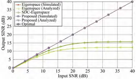
[image:5.595.312.535.556.692.2]The first set of simulations examines the output SINR of the proposed two-stage beamformer against white noise (input SNR). The corresponding results were shown in Figure 1. It is found that the output SINR values of the proposed scheme are close to those of the optimal one, confirming that the desired signal can be success-fully retained and the interference can be effectively suppressed even in case of a large pointing error. Under a proper condition ( SNRi5 dB), the eigenspace beam-former achieved a comparable performance as the optimal
Figure 1. Output SINR performance versus input SNR with 16
M , SIRi = 0 dB, s5.3
, K2, and Ns .
one. Unfortunately, for high input SNR (> 20 dB), both the eigenspace-based beamformers, as expected, pro-duced a significant degradation in output SINR. Fur-thermore, these beamformers reached the “saturation region” when the input SNR was larger than 20 dB. This is because that the residual interference buried in the beamformer output cannot be negligible when compared with the output noise power, leading to a limitation in performance. It is noteworthy that the analyzed output SINR close to the simulated results confirms correctness of the theoretical analysis.
The second set of simulations investigates the effect of input SIR. Figure 2 shows the output SINR versus input SIR. It is observed that the proposed beamformer pos-sessed an excellent robustness by effectively cancelling weak interference. On the contrary, the eigenspace beam- former failed to offer a reliable performance, especially for low input SIR (< -10 dB). Again, the reason for the significant discrepancy is that the pointing error effect induces a correlation between signals and makes the beamformer put less emphasis on suppressing interfer-ence. The analysis results approaching performance of the proposed beamformer confirm that the analysis re-sults are correct.
The third set of simulations evaluates the effect of pointing errors on the proposed beamformer. In this case, the look direction s was varied from 10
to 10, corresponding to a maximum pointing error of 10 (the null-to-null beamwidth of the broadside array is ap-proximately 14.4). Figure 3 shows the curves of output SINR versus s. The results indicate that desired signal
cancellation does not occur even with the desired source located out of the “main-beam”. On the other hand, both the conventional beamformers exhibit a significant deg-radation in SINR performance. Again, the correctness of the theoretical analysis was ascertained by achieving the similar results as the simulation results.
[image:5.595.63.282.564.692.2]The fourth set of simulations examines the capability
Figure 2. Output SINR performance versus input SIR with 16
M , SNRi = 20 dB, s5.3
Figure 3. Output SINR performance versus pointing error with M16, SNRi = 20 dB, SIRi = 0 dB, K2, and Ns . in interference suppression by varying the number of signal sources K. The resulting SINR plotted in Figure 4 indicates that desired signal cancellation did not occur with pointing error (no performance degradation) for
5
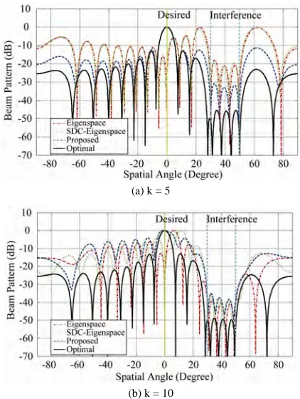
K . In an interference-rich environment (large values of K), the non-zero cross correlation between signals makes the proposed scheme exhibit a certain degradation in performance due to the beam squint effect. The con-ventional eigenspace-based beamformers are sensitive to the number of interferers. These are confirmed by the beam patterns shown in Figure 5(a) and Figure 5(b) obtained with K5 and 10, respectively. Clearly, all the beamformers successfully suppress interference even with a large pointing error. In the case of K 5, the proposed beamformer can resteer the beam back to the desired source direction to compensate for the error in the DOA estimate at the first stage. This did not happen with K10 (an interference-rich environment). In ad-dition, the conventional beamformers put a null in the direction of the desired signal, leading to a failure in beamforming.
The final set of simulations investigates the conver-gence behavior by varying the data sample size Ns for
computing the time-averaged version of the received data correlation matrix in (18). The results given in Figure 6 demonstrate that the proposed beamformer with a similar performance as the optimal one converges in about
3
10
s
N data samples, which is only about 0.37 dB away from the optimal case (Ns ). On the contrary, the other
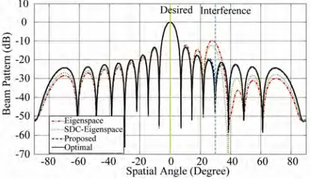
beamformers cannot collect the desired signal and com-pletely suppress the interference even in the case of 5000 data samples due to the pointing error. To gain further insights, we show in Figure 7 the beam patterns obtained with 103
s
[image:6.595.316.529.86.209.2]N . We note that although the interferer was not perfectly cancelled, the proposed beamformer was still able to impose sufficient attenuation on it to prevent performance breakdown. On the other hand, the conven-tional beamformers cannot eliminate the interferer due to both the effects of pointing error and finite sample.
Figure 4. Output SINR performance versus K with M 16, SNRi = 20 dB, SIRi = 0 dB, s5.3
, and Ns .
(a) k = 5
(b) k = 10
Figure 5. Beam pattern obtained with M16, SNRi = 20 dB,
SIRi = 0 dB, s5.3
, and Ns . (a) K5; (b) K10.
Figure 6. Output SINR performance versus sample size Ns with M16, SNRi = 20 dB, SIRi = 0 dB, K2, and s5.3
[image:6.595.317.528.248.528.2] [image:6.595.317.532.570.691.2]Figure 7. Beam pattern obtained with M16, SNRi = 20
dB, SIRi = 0 dB, K2, s5.3
, and 3
10 s N .
5. Conclusions
In this paper, we have derived an output SINR closed- form expression of the eigenspace beamformer in terms of three important parameters including pointing errors, input SNR, and SIR. According to these analytical results, we find some intrinsic constraints imposed on the eigen-space beamformer. These constraints inspire us to de-velop a new beamforming scheme for combating large pointing errors. Computer simulations are presented to verify the derivation of the corresponding analysis. It is shown that the proposed beamformer possesses a better resistance to the pointing errors and excellent capability of suppressing weak interference in comparison with the conventional techniques, especially at a low input SIR.
6. Acknowledgement
This work was sponsored by the National Science Coun-cil, R. O. C, under the Contract NSC 99-2221-E-239- 023.
REFERENCES
[1] R. A. Monzingo and T. W. Miller, Introduction to Adap-tive Arrays, New York, NY: John Wiley & Sons, 1980. [2] B. Widrow, K. M. Duvall, R. P. Gooch and W. C.
New-man, “Signal Cancellation Phenomena in Adaptive An-tennas: Causes and Cures,” IEEE Trans. Antennas and Propagat., Vol. 30, No. 5, pp. 469-478, May 1982. [3] B. D. Van Veen and K. M. Buckly, “Beamforming: A
Versatile Approach to Spatial Filtering,” IEEE ASSP Magazine, pp. 4-24, April 1988.
[4] M. H. Er, “Adaptive Antenna Array under Directional and Spatial Derivative Constraints,” Proc. IEE, pt. H, Vol. 135, No. 6, pp. 414-419, 1998.
[5] K. C. Huang and C. C. Yeh, “Performance Analysis of Derivative Constraint Adaptive Arrays with Pointing Er-rors,” IEEE Trans. Antennas and Propagat., Vol. 40, No. 8, pp. 975-981, Aug. 1992.
[6] Y. Chu and W. Y. Horng, “A Robust Algorithm for Adap-tive Interference Cancellation,” IEEE Trans. Antennas and Propagat., Vol. 56, No. 7, pp. 2121-2124, July 2008. [7] L. Chang and C. C. Yeh, “Effect of Pointing Errors on the
Performance of the Projection Beamformer,” IEEE Trans. Antennas and Propagat., Vol. 41, No. 8, pp. 1045-1056, Aug. 1993.
[8] M. H. Er and B. C. Ng, “A New Approach to Robust Beamforming in the Presence of Steering Vector Errors,” IEEE Trans. Signal Process., Vol. 42, No. 7, pp. 1826- 1829, July 1994.
[9] T. T. Lin, “A Two-Stage Beamformer with Enhanced Resistance Against Larger Pointing Errors,” in Proc. PIMRC 2009, Tokyo, Japan, pp. 983-987, Spet. 2009. [10] G. H. Golub and C. F. Van Loan, Matrix Computations,
2nd ed., Baltimore, MD: Johns Hopkins University Press, 1989.