Impact of Soft Magnetic Material on Design of
High Speed Permanent Magnet Machines
Nuwantha Fernando,
Member
,
IEEE
, Gaurang Vakil, Puvan Arumugam,
Member
,
IEEE
,
Emmanuel Amankwah, Chris Gerada,
Member
,
IEEE
, and Serhiy Bozhko,
Member
,
IEEE
Abstract—This paper investigates the effect of two soft magnetic materials on a high speed machine design, namely 6.5% Silicon Steel and Cobalt-Iron alloy. The effect of design parameters on the machine performance as an aircraft starter-generator is analysed. The material prop-erties which include B-H characteristics and the losses are obtained at different frequencies under an experiment and used to predict the machine performance accurately. In the investigation presented in this paper, it is shown that machines designed with 6.5% Silicon Steel at a high core flux density has lower weight and lower losses than the Cobalt-Iron alloy designs. This is mainly due to the extra weight contributed by the copper content especially in the end-windings. Due to the high operating frequen-cies, the core-losses in the Cobalt-Iron machine designs are found to outweigh the copper-losses incurred in the Silicon Steel machines. It is also shown that change in stack length/number of turns has a considerable effect on the copper losses at starting, however has no significant advantage on rated efficiency which happens to be in a field-weakening operating point. It is also shown that the performance of the machine designs depend significantly on material selection and the operating point of the core. The implications of the variation of design parameters on the machine performance is discussed and provides insight into the influence of parameters that effect overall power density.
Index Terms—Aircraft, cobalt steel, flux density, high speed, machine design, soft magnetic material, silicon steel
I. INTRODUCTION
D
UE to the increase in per-capita energy demand on-board aircraft and the associated weight penalty of power generation systems on the aircraft fuel consumption, the development of energy efficient aircraft generation systems are progressing rapidly [1]–[4]. One approach that may increase the power generation capability with low weight is to consider machines that operate at high speeds [5]–[14]. This result in increased losses in both the winding material and magneticManuscript received December 27, 2015; revised March 28, 2016 and April 28, 2016; accepted May 9, 2016. This work was funded under the 7th FWP (Seventh Framework Programme) Joint Technology Initiatives -theme Clean Sky. Project Code: JTI-CS-2011-1-ECO-02-009 Alternator with active power rectification and health monitoring
The corresponding author is Puvan Arumugam who is currently with Force Engineering Ltd, Shepshed, UK (email: [email protected])
Nuwantha Fernando is currently with the RMIT University, Melbourne Australia. (email: [email protected])
G. Vakil, E Amankwah, C. Gerada and S. Bozhko are with the Power Electronics, Machines and Control Group, Faculty of Engineering, The University of Nottingham, University Park, Nottingham NG7 2RD, U.K.
material due to high frequencies [15]. Minimizing these losses allows improvement of the design efficiency.
In general, electrical machines associated with aerospace and defence applications tend to employ Cobalt-Iron (Co-Iron) alloy material [16]. This is mainly due to the high temperature operating conditions often encountered in such application and especially high flux density capability of the Co-Iron alloy material which may allow weight minimization. In contrast, Silicon-Iron alloys and sintered soft magnetic materials are also extensively used in automotive [17]–[20] and industrial drive applications [21]–[23] due to their low losses. The sintered soft magnetic material is found to offer relatively poor structural characteristics whilst Silicon-Iron alloys provide increased tensile strength due to alloying high Silicon (Si) content with Iron (Fe).
(IPMSM) is shown at majority of operating conditions expect at high torque conditions. The authors of [29] present the enhancement of efficiency of high speed switched reluctance motors designed with Hiperco-50 (Cobalt-Iron alloy) and with conventional non-oriented Si-Steel 35A300. It is shown that a Co-Iron based switched reluctance machine achieves higher efficiency compared with a Si-Steel based design. The authors do not present any power density or weight comparison in their results.
The rationale of this paper is to compare the effect of two core material options, namely low-loss 6.5% Si-Steel and Co-Iron steel on the performance and weight of the overall machine design. Initially, the material properties such as the B-H characteristics and losses at different frequencies are obtained with an experiment and then these material data are used to predict the performance of the machine designs using finite element simulations. The effect of stack length, number of winding turns, outer diameter and no-load magnetic flux density of the machine on the performance are compared. It is shown that the machines designed with Si-Steel at high core flux density are considerably lower in weight and achieves lower core losses than the Co-Iron designs. It is also shown that that the Co-Iron designs result in high core-losses that outweigh the higher copper-loss penalty encountered in the Si-Steel based designs. The performance of the designed machines are found to depend heavily on material selection and the operating point of the core. Therefore these need to be accounted in the design to improve power density.
Section II describes the target application and specific requirements associated with this application. Section III presents the experimental evaluation of the properties of the candidate material used for the comparison in this paper. Section IV details the machine design procedure specifically adopted to cater for the high speed operational requirements and for the comparison of the machine designs. Section V discusses the influence of the two different material on the machine performance and provides key conclusions. Section VI concludes the paper.
II. TARGET APPLICATION
The target application of this research is an aircraft starter generator. In contrast with the existing aero-engine generator technology, a starter-generator performs both the tasks of aircraft starter operation as well as power generation during flight. The starter operation is of short-time duty, while the power generation mode requires in continuous duty operation. Due operation in dual modes, a considerable weight saving is predicted by future more-electric aircraft engine designs.
For the starter/generator considered in this research, a nominal power of 45 kW at 32000 rpm is required. Fig. 1 shows the torque (magnitude) vs. speed requirement of the starter generator. The machine runs as a motor during engine start and is required to supply constant positive torque of approximately 54 Nm (Tstart) from standstill to 8000 rpm
(ωstart). Between ωstart to ωmin the machine provides a
constant power to accelerate the engine until the engine is fired and achieves self-sustenance. When the machine reaches
Speed
Torque
start T
start
ω ωmin ωmax
generating motoring
rated operating
[image:2.612.317.552.68.204.2]point
Fig. 1. Torque-Speed requirement of the aircraft starter-generator
ωminthe engine is considered to have achieved self-sustenance and generator operation is initiated. In generation mode, the machine is required to produce maximum constant power of 45 kW up to a maximum speed (ωmax) of 32000 rpm.
III. EXPERIMENTAL EVALUATION OF MATERIAL PROPERTIES
(a)
(b)
(c)
(d)
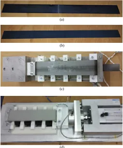
Fig. 2. Prepared material samples for testing: (a) Si-Steel sample and (b) Co-Iron alloy steel sample. (c) and (d) : Setup with the sample placed inside the testing unit during an experiment.
[image:2.612.311.565.351.655.2]0 0.5 1 1.5 2 2.5
0 2000 4000 6000 8000 10000 12000
Magnetic Flux density
B
(T
)
Magnetic flux intensity (AT) (a)
3000 Hz
Si-Steel data Co-Iron data Si-Steel (BH curve from datasheet) Co-Iron (BH curve from datasheet) 0
50 100 150 200 250 300 350
0 0.5 1 1.5 2 2.5
Co
re
L
os
se
s
(W
/k
g)
(b) Magnetic flux density B (T) 0 100 200 300 400 500 600 700 800 900 1000
0 0.5 1 1.5 2 2.5
Co
re
L
os
se
s
(W
/k
g)
(c) Magnetic flux density B (T)
0 500 1000 1500 2000 2500
0 0.5 1 1.5 2 2.5
Co
re
L
os
se
s
(W
/k
g)
(d) Magnetic flux density B (T) 0 500 1000 1500 2000 2500 3000 3500
0 0.5 1 1.5 2 2.5
Co
re
L
os
se
s
(W
/k
g)
(e) Magnetic flux density B (T) 0 500 1000 1500 2000 2500 3000 3500 4000 4500
0 0.5 1 1.5 2 2.5
Co
re
L
os
se
s
(W
/k
g)
(f) Magnetic flux density B (T)
1000 Hz 2000 Hz
5000 Hz 4000 Hz
3000 Hz
Fig. 3. (a) B-H characteristics and loss comparison of the two candidate materials - Silicon Steel and Cobalt-Alloy steel at different frequencies: (a) 1000 Hz, (b) 2000 Hz, (c) 3000 Hz, (d) 4000 Hz and (e) 5000 Hz.
design process. In addition, high power density is also a key criterion of the machine design. To achieve both high power density and high efficiency within the design, the selection of the material and its utilisation are important. Herein, two materials namely Co-Iron and 6.5% Si-Steel are considered for the design. The Co-Iron has significantly higher saturation flux density than Steel as shown in Fig. 3 (a). However, Si-Steel has lower W/kg losses against frequency under normal operation. To perform an effective design, the properties of the materials are initially evaluated via an experiment and then integrated within Finite Element (FE) numerical tool.
The in-house material characterisation experimental setup uses three different methods to evaluate the core losses. The methods are the Epstein frame, single sheet tester and toroid core measurement methods. In this experiment, the both the Epstein frame based tests and single sheet tests have been performed. An example of the samples used for the tests are shown in Fig. 2 (a) and (b). The sampled being tested in the single sheet testing setup is shown in Fig. 2 (c) and (d).
TABLE I
SPECIFICATIONS ANDCAPABILITIES FORMEASUREMENTFACILITY
Parameter Quantity
Fundamental Frequency 5 to 100 kHz
Low Frequency Amplifier Capacity 100V 52 A (Peak)
(up to 20kHz - fundamental excitation) 60V 40A,(Continuous)
High Frequency Amplifier Capacity 50V 10A
(peak & continuous) (up to 100kHz - nonsinusoidal / PWM )
Operating temperature:
Soft Magnetic Materials -40C to 180C
Hard Magnetic Materials -40C to 300C
Operating stress (compression):
Soft Magnetic Materials 0 to 3kN
Hard Magnetic Materials 0 to 1kN
Excitation waveform capability: Sine Wave, DC / Normalized,
PWM, Harmonic injection
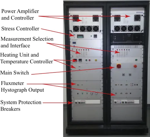
Fig. 4 shows the main interface of the measurement sys-tem that includes the power amplifier, measurement options, debugging options, heating unit, flux meter connections, real
Power Amplifier and Controller Stress Controller Measurement Selection and Interface
Heating Unit and Temperature Controller
Fluxmeter Hystograph Output
System Protection Breakers
[image:3.612.63.555.62.243.2]Main Switch
Fig. 4. Main interface of the state of art testing facility available in-house
time computer interface, and system protection arrangements. The setup specifications are shown in Table I. The power measurement is performed using a high fidelity system which consists of a linear power amplifier with high bandwidth and is IEC 60404 certified. The test samples are cut in standard geometry and tested according to specifications of the IEC 60404 standard. Device calibration has been performed with sinusoidal excitation and the form factor has been tightly governed in these tests. The final data has been gathered from several repetitive tests. The facility also provides the ability to perform the characterisation tests at any desired temperature and pressure depending on the furnace capability. Tests under multiple pressure and temperature values has not been considered in this study.
[image:3.612.319.564.294.519.2]experiments for estimation of losses. Loss measurements at high magnetic flux density and high frequency have been possible with the single sheet tests. All the measurements are performed under pure sine wave excitation. The primary current and secondary voltage is then recorded. The complete hysteresis curve is generated using these two quantities and the B-H curves are obtained. The total iron losses are obtained by the high fidelity power measurement system presented in Table I. The copper losses are then subtracted. A temperature compensation is also provided to make sure that any change in resistance is compensated. The hysteresis losses are calculated by the area under the B-H curve. The remainder of the losses are assumed to be the eddy current and excess losses.
From Fig. 3 (a), it can clearly be seen that the measured B-H characteristics slightly varies from the data provided by the manufacturer due to variations during manufacture. However, they are in close agreement. It can also be seen from Fig. 3 (b) to (f) that as expected the losses increase with both flux density and frequency. The Si-Steel losses are higher than Co-Iron losses in the saturated region. This gives an indication that the design may be highly influenced by the region of the B-H curve where the machine is designed to be operated. The design has therefore been carried out based on both the material options and their characteristics obtained though these experiments. This will be detailed in the following section.
IV. MACHINE DESIGN STRATEGY
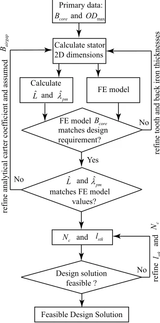
The procedure adopted for the design of the machines to satisfy the stipulated operating point conditions is outlined in Fig. 5. The design process involves specification of the core no-load flux densityBcoreand the maximum stator outer diameterODmax. The stator back-iron thickness and the stator tooth widths are direct function of these two specifications. Hence the preliminary stator dimensions for a given rotor pole number and SPP (slot per pole per phase) value can be determined such that the specified requirements are met. Dimensions such as slot opening and slot wedge thicknesses are maintained such that the tooth-edge flux density under no-load conditions remains the same as that of the tooth flux density, and hence offers a fair comparison in the analysis of the different designs. The rotor is designed with consideration on mechanical integrity and to achieve the highest power density within the given space-envelope for the machine [5]. The stator design is performed considering a bore diameter of 92 mm, air-gap thickness of 2 mm, magnet retention sleeve thickness of 4 mm and magnet thickness of 10 mm.
Based on the stator structure and the fixed rotor construc-tion, the inductance and flux-linkage per-unit stack-length and unit winding-turns denoted by Lˆ and ˆλpm are calculated. Simultaneously, the machine design is implemented in an FE package and the stator core maximum flux density and the FE based values of Lˆ andˆλpmare also evaluated. Following the matched Lˆ and λˆpm, the feasible stack length and number of turns per winding are calculated. A feasibility machine design represents a machine with ability to satisfy maximum current limitation of 360 A, maximum voltage limitation of 270 V during both starting and field weakening operations.
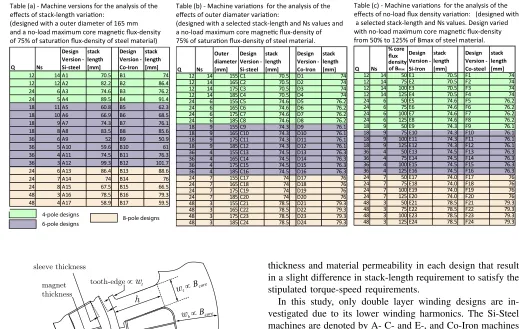
It is found that for a given rotor pole number and SPP combination, multiple feasible solutions exist. The different feasible machine design under different parametric variations are obtained as shown in Tables II (a) to (c) and are discussed in the following section.
V. INFLUENCE OF THE MATERIAL ON DESIGN
In this section, the variation of stack-lengthlstkbetween 50 mm to 100 mm and outer diameterOD between 155 mm to 185 mm, andBcorevalue between 50% to 125% of theBmax value are investigated. From Fig. 3, the nominal maximum flux density Bmax values are selected as 1.25 T and 2.05 T for Si-Steel and Co-Iron respectively.
These ranges of values are selected in this analysis to allow for an appreciable comparison of the variations of these parameters on the machine designs and their performance with the use of the two core material. The Bcore value is specifically varied between 50% to 75% to capture the percentage improvement in power density and efficiency in the non-saturated region, and to 125% to capture the performance in the saturated region.
Fig. 6 outlines the 2-dimensional parameters, namely stator outer diameter OD, tooth width wt, back-iron heightwb and tooth height hand their dependency on other parameters as explained in Section IV. The analysis is performed in three parts. Tables II (a), (b) and (c) outline the different versions
c
N
No
refine
st
k
l
Yes
Feasible Design Solution Primary data:
core
B ODmax
Calculate stator 2D dimensions
andLˆ λˆpm Calculate
FE model
FE modelBcore
matches design requirement?
refine tooth and back iron thicknesses
andˆ
L λˆpm
matches FE model values?
refine analytical carter coef
ficient and assumed
ai
rg
ap
B
c N and lstk
No
Design solution feasible ?
No
and
[image:4.612.355.518.395.723.2]and
TABLE II
THE DIFFERENT FEASIBLE MACHINE DESIGNS OBTAINED UNDER DIFFERENT PARAMETRIC VARIATIONS
Table (a) - Machine versions for the analysis of the
effects of stack-length variation:
(designed with a outer diameter of 165 mm and a no-load maximum core magnetic flux-density of 75% of saturation flux-density of steel material)
Table (b) - Machine variations for the analysis of the
effects of outer diamater variation:
(designed with a selected stack-length and Ns values and a no-load maximum core magnetic flux-density of 75% of saturation flux-density of steel material.
Table (c) - Machine variations for the analysis of the
effects of no-load flux density variation: (designed with a selected stack-length and Ns values. Design varied with no-load maximum core magnetic flux-density from 50% to 125% of Bmax of steel material.
p Q Ns % core flux density of Bmax
Design Version - Si-Iron
stack length [mm]
Design Version - Co-steel
stack length [mm] 4 12 14 50E1 70.5 F1 74 4 12 14 75E2 70.5 F2 74 4 12 14 100E3 70.5 F3 74 4 12 14 125E4 70.5 F4 74 4 24 6 50E5 74.6 F5 76.2 4 24 6 75E6 74.6 F6 76.2 4 24 6 100E7 74.6 F7 76.2 4 24 6 125E8 74.6 F8 76.2 6 18 9 50E9 74.3 F9 76.1 6 18 9 75E10 74.3 F10 76.1 6 18 9 100E11 74.3 F11 76.1 6 18 9 125E12 74.3 F12 76.1 6 36 4 50E13 74.5 F13 76.3 6 36 4 75E14 74.5 F14 76.3 6 36 4 100E15 74.5 F15 76.3 6 36 4 125E16 74.5 F16 76.3 8 24 7 50E17 74.0 F17 76 8 24 7 75E18 74.0 F18 76 8 24 7 100E19 74.0 F19 76 8 24 7 125E20 74.0 F20 76 8 48 3 50E21 78.5 F21 79.3 8 48 3 75E22 78.5 F22 79.3 8 48 3 100E23 78.5 F23 79.3 8 48 3 125E24 78.5 F24 79.3
p Q Ns
Outer diameter [mm]
Design Version - Si-steel
stack length [mm]
Design Version - Co-Iron
stack length [mm] 4 12 14 155C1 70.5 D1 74 4 12 14 165C2 70.5 D2 74 4 12 14 175C3 70.5 D3 74 4 12 14 185C4 70.5 D4 74 4 24 6 155C5 74.6 D5 76.2 4 24 6 165C6 74.6 D6 76.2 4 24 6 175C7 74.6 D7 76.2 4 24 6 185C8 74.6 D8 76.2 6 18 9 155C9 74.3 D9 76.1 6 18 9 165C10 74.3 D10 76.1 6 18 9 175C11 74.3 D11 76.1 6 18 9 185C12 74.3 D12 76.1 6 36 4 155C13 74.5 D13 76.3 6 36 4 165C14 74.5 D14 76.3 6 36 4 175C15 74.5 D15 76.3 6 36 4 185C16 74.5 D16 76.3 8 24 7 155C17 74 D17 76 8 24 7 165C18 74 D18 76 8 24 7 175C19 74 D19 76 8 24 7 185C20 74 D20 76 8 48 3 155C21 78.5 D21 79.3 8 48 3 165C22 78.5 D22 79.3 8 48 3 175C23 78.5 D23 79.3 8 48 3 185C24 78.5 D24 79.3
Q Ns
Design Version - Si-steel
stack length [mm]
Design Version - Co-Iron
stack length [mm]
4 12 14 A1 70.5 B1 74
4 12 12A2 82.2 B2 86.4 4 24 6A3 74.6 B3 76.2 4 24 5A4 89.5 B4 91.4
6 18 11A5 60.8 B5 62.3
6 18 10A6 66.9 B6 68.5
6 18 9 A7 74.3 B7 76.1
6 18 8 A8 83.5 B8 85.6
6 36 6A9 52 B9 50.9
6 36 5A10 59.6 B10 61
6 36 4 A11 74.5 B11 76.3 6 36 3 A12 99.3 B12 101.7 8 24 6A13 86.4 B13 88.6 8 24 7 A14 74 B14 76 8 24 8 A15 67.5 B15 66.5 8 48 3 A16 78.5 B16 79.3 8 48 4 A17 58.9 B17 59.5
4-pole designs
6-pole designs 8-pole designs
OD
sleeve thickness
bore-diameter magnet
thickness h
wb wt wt
tooth-edge ∝
wt
slot-opening∝
∝Bcore
∝Bcore
Fig. 6. Outline of a machine section with dimensions and the parameters that influence their selection
of feasible machine designs considered in the analysis.
Part-1: OD is fixed at 165 mm andBcore at 75% Bmax of the corresponding material. lstk and turns-per-slot Ns are varied. Resultant feasible designs are given in Table II (a). Part-2 : OD is varied from 155 mm to 185 mm. Bcore is fixed at 75% Bmax of the corresponding material. lstk and Ns are varied. Resultant feasible designs are given in Table II (b).
Part-3 : OD is fixed at 165 mm. Bcore is varied from 50% Bmaxto 125%Bmaxof the corresponding material.lstkand Ns are varied. Resultant feasible designs are given in Table II (c).
The 4-pole, 6-pole and 8-pole rotor options are considered and are highlighted in Tables II (a), (b) and (c) in different shades. These machine designs are obtained according to the procedure outlined in Section IV. For each slot-pole combination, the Si-steel designs and Co-steel designs achieve moderately close values of stack-length. However, the vari-ation of the stack length is due to the difference in tooth
thickness and material permeability in each design that result in a slight difference in stack-length requirement to satisfy the stipulated torque-speed requirements.
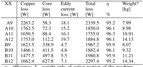
In this study, only double layer winding designs are in-vestigated due to its lower winding harmonics. The Si-Steel machines are denoted by A- C- and E-, and Co-Iron machines are denoted by B-, D- and F- points as shown in Tables II (a), (b) and (c). The breakdown of losses, namely the steel core losses, eddy current losses in the magnets and the copper losses in the windings are obtained via FE simulations and the efficiencies at the rated operating point at a speed of 32000 rpm and output power of 45 kW is calculated. The machine weight and efficiency results are summarised in Fig. 7, 8 and 9.
A. Part - 1 : Variation of stack length and number of turns
The following are key observations from this analysis:
1) The efficiency variation with the increase in stack length is in the range of 1% for majority of the machines.
An example of this with the 6-pole / 36-slot machine designs is highlighted by lines L1 to L4 and the breakdown of loss components are shown in Table III. With higher stack-lengths, a higher field weakening current requirement yields higher copper losses. However, the maximum copper losses at starting is reduced as stack-length is increased due to resultant higher PM flux-linkage achieved. Hence, the change in efficiency is low.
2) The Co-Iron machine designs are found to be heavier than the Si-Steel machine designs.
[image:5.612.44.563.86.415.2]Efficiency [%]
weight [kg]
7 8 9 10 11 12 13 14 15
90 91 92 93 94 95 96 97 98 99 100
A1 A2
A3 A4
A5 A6 A7 A8
A9
A10
A11 A12
A13 A14
A15 A16
A17
B1 B3 B2 B4
B5
B6 B7 B8
B9
B10 B11
B12
B13 B14
B15 B16
B17
L1 L2 L3 L4
Results with varitation of stack-length and Number of turns
copper loss
at starting [W] >5000 4500 4000 3500 3000 2500 2000
Fig. 7. Variation of efficiency and weight for feasible machine solutions for different stack length and number of turns per slot with fixed outer diameter at 165 mm and fixed no-load core flux density at 75% ofBmax
(Design versions A- are with Si-Steel and B- are with Co-Iron material)
TABLE III
BREAKDOWN OF LOSS COMPONENTS FOR THE6-POLE, 36-SLOT MACHINE DESIGNS WITH VARIEDlstkANDNs
XX Copper Core Eddy Total η Weight*
loss loss current loss [kg]
[W] [W] loss [W] [W] %
A9 2263.2 58.3 18.1 2339.5 95.2 7.99
A10 1762.5 72.3 15.2 1850.0 96.1 8.98
A11 1650.5 88.4 16.1 1755.0 96.3 10.91
A12 1753.0 112.2 19.7 1884.8 96.1 14.13
B9 1623.5 338.9 4.7 1967.2 95.9 8.07
B10 1466.1 411.5 4.8 1882.4 96.1 9.32
B11 1477.5 497.8 5.5 1980.8 95.9 11.21
B12 1662.4 627.8 7.1 2297.4 95.2 14.34
η- efficiency, * - weight only of active portion of the machine
stator weight with Co-Iron is outweighed by the higher copper weight.
B. Part - 2 : Variation of outer diameter / split ratio This analysis is performed by varying the outer diameter from 155 mm to 185 mm over four steps. The split ratio is defined as:
split ratio =inner diamater
outer diamater (1)
This variation in outer diameter corresponds to split ratios of 0.5935, 0.5576, 0.5257 and 0.4973 respectively. For each rotor pole and SPP combination, the tooth thickness and back-iron thickness hence remains the same. The increase in the outer diameter results in a higher tooth height and more area for the copper winding at the cost of a heavier machine. The following are key observations from this analysis:
1) The change in the outer diameter has minimal effect on the PM-flux linkage for each slot and SPP combination. As a result, the machines with the same rotor pole number and SPP combination yield feasible machine solutions with approximately the same stack length. However, the increase in
TABLE IV
BREAKDOWN OF WEIGHTS OF DIFFERENT COMPONENTS OF THE MACHINE DESIGN FOR TWO6-POLE36-SLOT DESIGN VERSIONS-lstk
VARIATION
XX Stator Rotor Magnet Sleeve Copper Total*
[kg] [kg] [kg] [kg] (main) (end) [kg]
A10 4.53 1.09 1.09 0.12 0.90 1.24 8.98
B10 3.86 1.12 1.12 0.12 1.31 1.79 9.32
* - weight only of active portion of the machine
Efficiency [%]
weight [kg]
8 9 10 11 12 13 14 15 16 17 90
91 92 93 94 95 96 97 98 99 100
C2
C3
C4
C6
C7
C8 C9
C10
C11 C12
C13
C14
C15 C16
C17
C18 C19
C20 C21
C22 C23
C24
D2
D3
D4 D6
D7
D8 D9
D10 D11
D12
D13
D14
D15 D16
D17
D18 D19 D20 D21
D22 D23
D24
L5 L6
L7
L8 Results with varitation of Outer-diameter
1500 2000 2500 3000 >3500
[image:6.612.58.290.345.455.2]copper loss at starting [W]
Fig. 8. Variation of efficiency and weight for feasible machine solutions for different outer diameter (155 mm, 165 mm 175 mm and 185 mm) for feasible machine designs with stack length between 70 mm to 80mm and fixed no-load core flux density at 75% of Bmax. Design versions C-are with Si-Steel and D- C-are with Co-Iron material
the outer diameter results in a higher inductance that translate to a lower current requirement at the field weakening operating point at 32000 rpm. Furthermore, increase in outer diameter also result in more area for copper and lower copper losses. This results in an added increase in efficiency at the cost of a heavier machine.
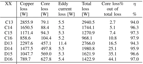
An example with C13 to C16 for the Si-Steel machines and D13 to D16 for the Co-Iron machines is given in Table V. The reduction in split ratio from 0.5935 to 0.5576 results in an increase in efficiency by 2.3% and 1.6% for the Si-Steel machines and Co-Iron machines respectively. The reduction in split ratio from 0.5935 to 0.4973 results in a total increase of in efficiency of 3.9% and 2.7% for the Si-Steel machines and Co-Iron machines respectively.
2) As the outer diameter is increased (split ratio is reduced), the difference between the weights of the Si-Steel ma-chines and the Co-Iron mama-chines further expand.
TABLE V
BREAKDOWN OF LOSS COMPONENTS FOR THE6-POLE, 36-SLOT MACHINE DESIGNS WITH VARIEDOD
XX Copper Core Eddy Total Core loss% η
loss loss current loss out of
[W] [W] loss [W] [W] total loss %
C13 2855.9 79.1 5.5 2940.5 2.7 94.0
C14 1650.5 88.4 5.2 1744.1 5.1 96.3
C15 1171.4 94.3 5.3 1270.9 7.4 97.3
C16 858.6 104.4 5.2 968.1 10.8 97.9
D13 2297.6 457.1 11.4 2766.0 16.5 94.3
D14 1477.5 497.8 5.5 1980.8 25.1 95.9
D15 1047.7 569.0 5.3 1621.9 35.1 96.6
D16 789.7 627.8 5.4 1422.9 44.1 97.0
split ratios : C13 & D13 - 0.5935, C14 & D14 - 0.5576 C15 & D15 - 0.5257 and C16 & D16 - 0.4973
η- efficiency
TABLE VI
BREAKDOWN OF WEIGHTS OF DIFFERENT COMPONENTS OF THE MACHINE DESIGN FOR6-POLE36-SLOT DESIGN VERSIONS-SPLIT
RATIO VARIATION
XX Stator Rotor Magnet Sleeve Copper Total
[kg] [kg] [kg] [kg] (main) (end) [kg]
C13 4.89 1.36 1.37 0.14 0.72 0.77 9.25
D13 4.26 1.40 1.40 0.15 1.10 1.16 9.47
C14 5.59 1.36 1.37 0.14 1.17 1.29 10.92
D14 4.83 1.40 1.40 0.15 1.64 1.79 11.21
C15 6.29 1.36 1.37 0.14 1.66 1.91 12.74
D15 5.41 1.40 1.40 0.15 2.22 2.54 13.11
C16 6.96 1.36 1.37 0.14 2.19 2.61 14.63
D16 5.98 1.40 1.40 0.15 2.86 3.40 15.18
Co-Iron machines respectively.
C. Part - 3 : Variation of design no-load core flux density
Efficiency [%]
weight [kg]
7 8 9 10 11 12 13 14 15
90 91 92 93 94 95 96 97 98 99 100
E2
E3 E4
E5 E6
E7 E8
E9 E10
E11 E12
E13 E14
E15 E16
E17 E18 E19
E20 E22 E21
E23 E24
F1 F2
F3 F4
F5 F6
F7 F8
F9 F10
F11
F12 F16F15 F14 F13 F17
F18 F19
F20 F21
F22 F23 F24
L9 L10
L11 L12
Results with varitation of design no-load core flux-density
[image:7.612.53.297.91.200.2]2000 2500 3000 3500 4000 4500 >5000 copper loss at starting [W]
Fig. 9. Variation of efficiency and weight for feasible machine solutions for different no-load flux density selections (50%, 75%, 100% and 125% of Bmax) for feasible machine designs with stack length between 70 mm to 80mm and outer diameter of 165mm. Design versions E- are with Si-Steel and F- are with Co-Iron core material.
Both the earlier analyses have been performed on machines designed with a no-load core flux density Bcore at 75% of
the nominal maximum flux densityBmax. In this section, the Bcoreis varied from 50%, 75% 100% and 125% ofBmax re-spectively. The 125% case represents the design of a machine in the saturated region and hence the effects of saturation on the field-weakening operating point are accommodated in the analysis.
Based on the results in Fig. 9, the following key observa-tions are made:
1) As the pole number increases, higher efficiency is ob-served.
TABLE VII
BREAKDOWN OF LOSS COMPONENTS FOR THE4-POLE, 6-POLE AND
8-POLE, 2-SPPMACHINE DESIGNS WITHBcoreAT125%OFBmax
XX pole- Copper Core Eddy Total η
pairs loss loss current out of
[W] [W] loss [W] %
E8 4 3448.0 97.4 119.7 3665.1 92.6
E16 6 1971.8 137.1 13.8 2122.6 95.6
E24 8 1104.8 120.1 30.7 1255.6 97.3
F8 4 2865.6 519.4 141.7 3526.6 92.9
F16 6 1335.8 739.0 10.0 2084.8 95.7
F24 8 859.4 781.7 38.2 1679.3 96.5
As the pole number increases, higher efficiency is observed for all variations of Bcore values. As an example, Table VII shows the variation of efficiency and losses with incremented pole-pair numbers for both the Si-Steel and Co-Iron designs. With higher pole-pair number, the back-iron requirement is reduced, and hence more area for copper is available. This results in lower copper losses in the 8-pole machine designs resulting in an improvement in efficiency.
2) As the Bcore value is increased, the relative difference in weight between the Si-Steel and Co-Iron machines widens.
TABLE VIII
BREAKDOWN OF WEIGHTS OF DIFFERENT COMPONENTS OF THE MACHINE DESIGN FOR6-POLE36-SLOT DESIGN VERSIONS-Bcore
VARIATION
XX Stator Rotor Magnet Sleeve Copper Total
[kg] [kg] [kg] [kg] (main) (end) [kg]
E13 8.03 1.36 1.37 0.14 0.88 0.98 12.76
E14 5.20 1.36 1.37 0.14 1.21 1.34 10.62
E15 3.84 1.36 1.37 0.14 1.38 1.52 9.61
E16 3.04 1.36 1.37 0.14 1.48 1.62 9.02
F13 7.43 1.40 1.40 0.15 1.29 1.42 13.08
F14 5.20 1.40 1.40 0.15 1.59 1.74 11.47
F15 5.20 1.40 1.40 0.15 1.59 1.74 11.47
F16 2.84 1.40 1.40 0.15 1.91 2.09 9.79
D. The following are key general observations are also obtained from the analysis:
1) The 4-pole machines generally under-perform in compar-ison with the remaining machine designs.
Overall the efficiency of the 4-pole machines is below 94% for majority of the 4-pole machines and the copper losses at the 8000 rpm starting condition is above 3.5 kW. Hence the 4-pole machines can be considered as unsuitable for this application. 2) Compared with the Co-Iron machines, Si-Steel machines
yield higher copper losses.
This is mainly due to the lower area for the copper winding in the Si-Steel machine designs. However, the reduction in core losses in the Si-Steel for this particular machine design is found to outweigh the copper losses for majority of the 6-pole and 8-pole machine designs. Hence as observed in Figs. 7 to 9 for a large cohort of 6-pole and 8-pole machines, higher efficiency is achieved by the Si-Steel machines with a reduction in weight by at least 3.8% for the 6-pole machines and 1.4% for the 8-pole machines compared to Co-Iron machine.
The 8-pole machines offer superior overall performance over efficiency and weight. However, evaluation of power electronic and drive system efficiency reveal that the power electronic converter may be compromised with higher losses due to high power frequency. Hence, the prototype selection is based on the 6-pole machine options. Based on the analysis performed, it can be deduced that the best option is Si-Steel due to the lower weight offered and the comparatively low cost of material. The copper losses at starting is limited below 3.5 kW due to cooling limitations. Furthermore, with allowance for the machine casing and cooling space, the outer diameter of 165 mm is selected and the machine option of 6-pole 36-slot design is selected and designed for a no-load flux density of 75% Bmax.
VI. CONCLUSION
The effect of two soft magnetic materials, namely Si-Steel and Co-Iron on the machine design has been investigated. The material properties of these two candidate Steels have been experimentally evaluated and their B-H characteristics and the core losses have been obtained. Based on this information, an aircraft starter-generator design is considered. The variation of the stack-length and number of winding turns, the outer diameter of the machine and the variation of the design core flux density have been investigated. The key observations can be summarised as:
1. Increase in slot area/copper area in Co-Iron machines reduces the core steel weight. However, this increases the overall machine weight due to higher copper volume especially due to the end-windings. Although the copper losses are reduced due to increase in copper volume, in majority of the machines the increase coreless outweighs the reduction in copper loss in comparison with Si-Steel machines.
2. There is no significant advantage on efficiency (at rated operating point) by increase of stack length and number of turns due to increase in field weakening requirement. The change in efficiency is found to be within 1%. However, the
changes in stack length are found to impact the copper losses incurred at the starting condition.
3. For different stack-length and number of turn combina-tions, the reduction in copper losses from a Si-Steel design to a Co-Iron design for 6-pole and 8-pole machine designs is found to be in the range of 5% to 28% for an increase in overall weight in the range of 0.05 kg to 0.7 kg.
4. A reduction in split ratio from 0.5935 to 0.5576 has shown an increase in efficiency by 2.3% and 1.6% for the Si-Steel machines and Co-Iron machines respectively. This is for an increase in weight by 1.66 kg and 1.74 kg respectively. Similarly, the reduction in split ratio from 0.5935 to 0.4973 has shown an increase of in efficiency of 3.95% and 2.67% for the Si-Steel machine and Co-Iron machines respectively. This is for an increase in weight by 1.97 kg and 2.07 kg respectively. 5. For the 6-pole/36 slot case, the increase in flux density from 50% Bmax to 125% Bmax resulted in an increase in core losses by 3.6% for the Si-Steel machines and 15.8% for the Co-Iron machines, whilst reduction in the weight is 3.74 kg and 3.3 kg respectively. Similar trend has also been found in other slot/pole combinations.
In Conclusion, the Si-Steel machines appear to outperform the Co-Iron machines both in-terms of weight and efficiency for the application considered. Although Co-Iron material is more expensive than the Si-Steel material, there is no advantage of a machine designed with the more expensive material. This also confirms the fact that the machine design depends significantly on material selection and the operating point of the core. These need to be accounted for in the design to improve power density.
REFERENCES
[1] Y. Jia and K. Rajashekara, “An induction generator based ac/dc hybrid
electric power generation system for more electric aircraft,” in IEEE
Industry Applications Society Annual Meeting, 2015, Oct 2015, pp. 1– 7.
[2] R. Bojoi, A. Cavagnino, A. Tenconi, and S. Vaschetto, “Control of
shaft-line-embedded multiphase starter/generator for aero-engine,”IEEE
Trans. Ind. Electron., vol. 63, no. 1, pp. 641–652, Jan 2016.
[3] D. Wu, R. Todd, and A. J. Forsyth, “Adaptive rate-limit control for
energy storage systems,”IEEE Trans. Ind. Electron., vol. 62, no. 7, pp.
4231–4240, July 2015.
[4] E. Levi, “Advances in converter control and innovative exploitation of
additional degrees of freedom for multiphase machines,” IEEE Trans.
Ind. Electron., vol. 63, no. 1, pp. 433–448, Jan 2016.
[5] W. U. N. Fernando and C. Gerada, “High speed permanent magnet machine design with minimized stack-length under electromagnetic and
mechanical constraints,”Int J Appl Electrom., vol. 46, no. 1, pp. 95–109,
Jan 2014.
[6] A. Boglietti, C. Gerada, and A. Cavagnino, “High-speed electrical
machines and drives [special section intro.],”IEEE Trans. Ind. Electron.,
vol. 61, no. 6, pp. 2943–2945, June 2014.
[7] J. Boisson, F. Louf, J. Ojeda, X. Mininger, and M. Gabsi, “Analytical ap-proach for mechanical resonance frequencies of high-speed machines,” IEEE Trans. Ind. Electron., vol. 61, no. 6, pp. 3081–3088, June 2014. [8] A. Borisavljevic, H. Polinder, and J. A. Ferreira, “On the speed limits
of permanent-magnet machines,” IEEE Trans. Ind. Electron., vol. 57,
no. 1, pp. 220–227, Jan 2010.
[9] D. Gerada, A. Mebarki, N. L. Brown, K. J. Bradley, and C. Gerada, “De-sign aspects of high-speed high-power-density laminated-rotor induction
machines,”IEEE Trans. Ind. Electron., vol. 58, no. 9, pp. 4039–4047,
Sept 2011.
[10] D. Gerada, A. Mebarki, N. L. Brown, C. Gerada, A. Cavagnino, and A. Boglietti, “High-speed electrical machines: Technologies, trends, and
developments,” IEEE Trans. Ind. Electron., vol. 61, no. 6, pp. 2946–
[11] A. Tenconi, S. Vaschetto, and A. Vigliani, “Electrical machines for
high-speed applications: Design considerations and tradeoffs,”IEEE Trans.
Ind. Electron., vol. 61, no. 6, pp. 3022–3029, June 2014.
[12] A. Tuysuz, C. Zwyssig, and J. W. Kolar, “A novel motor topology for
high-speed micro-machining applications,”IEEE Trans. Ind. Electron.,
vol. 61, no. 6, pp. 2960–2968, June 2014.
[13] N. Uzhegov, E. Kurvinen, J. Nerg, J. Pyrhonen, J. T. Sopanen, and S. Shirinskii, “Multidisciplinary design process of a 6-slot 2-pole
high-speed permanent-magnet synchronous machine,”IEEE Trans. Ind.
Elec-tron., vol. 63, no. 2, pp. 784–795, Feb 2016.
[14] A. Aigbomian, P. Arumugam, T. Hamiti, and C. Gerada, “Fast computing tool for performance evaluation in interior permanent magnet machines,” inInt. Conf. on Electrical Machines (ICEM), Sept 2014, pp. 2722–2727. [15] P. Arumugam, T. Hamiti, and C. Gerada, “Estimation of eddy current loss in semi-closed slot vertical conductor permanent magnet
syn-chronous machines considering eddy current reaction effect,” IEEE
Trans. Magn., vol. 49, no. 10, pp. 5326–5335, Oct 2013.
[16] D. J. Powell, G. W. Jewell, S. D. Calverley, and D. Howe, “Iron loss in a modular rotor switched reluctance machine for the ”more-electric”
aero- engine,”IEEE Trans. Magn., vol. 41, no. 10, pp. 3934–3936, Oct
2005.
[17] S. P. Nikam and B. G. Fernandes, “Design of soft magnetic composite
based modular four phase srm for electric vehicle application,” inInt.
Conf. on Electrical Machines (ICEM), Sept 2014, pp. 112–116. [18] D. Dorrell, L. Parsa, and I. Boldea, “Automotive electric motors,
generators, and actuator drive systems with reduced or no permanent
magnets and innovative design concepts,”IEEE Trans. Ind. Electron.,
vol. 61, no. 10, pp. 5693–5695, Oct 2014.
[19] L. Ferraris, P. Ferraris, E. Poskovic, and A. Tenconi, “Theoretic and experimental approach to the adoption of bonded magnets in fractional
machines for automotive applications,” IEEE Trans. Ind. Electron.,
vol. 59, no. 5, pp. 2309–2318, May 2012.
[20] W. Zhao, T. A. Lipo, and B. il Kwon, “Material-efficient permanent-magnet shape for torque pulsation minimization in spm motors for
automotive applications,”IEEE Trans. Ind. Electron., vol. 61, no. 10,
pp. 5779–5787, Oct 2014.
[21] R. D. Stefano and F. Marignetti, “A comparison between soft magnetic
cores for axial flux pm synchronous machines,” in Int. Conf. on
Electrical Machines (ICEM), Sept 2012, pp. 1922–1927.
[22] R. H. Qu, “Keynote talk 2014 - design of large electrical machines,” inIEEE Int. Conf. on Applied Superconductivity and Electromagnetic Devices (ASEMD 2013), Oct 2013, pp. 536–536.
[23] W. Zhao, T. A. Lipo, and B. il Kwon, “Dual-stator two-phase perma-nent magnet machines with phase-group concentrated-coil windings for
torque enhancement,”IEEE Trans. Magn., vol. 51, no. 11, pp. 1–4, Nov
2015.
[24] J. Ma, R. Qu, and J. Li, “A novel axial flux switched reluctance
motor with grain oriented electrical steel,” in Magnetics Conference
(INTERMAG), 2015 IEEE, May 2015, pp. 1–1.
[25] R. Kolano, A. Kolano-Burian, K. Krykowski, J. Hetmanczyk,
M. Hreczka, M. Polak, and J. Szynowski, “Amorphous soft magnetic core for the stator of the high-speed pmbldc motor with half-open slots,” IEEE Trans. Magn., vol. PP, no. 99, pp. 1–1, 2016.
[26] M. N. Ibrahim, P. Sergeant, and E. M. Rashad, “Synchronous reluctance
motor performance based on different electrical steel grades,” IEEE
Trans. Magn., vol. 51, no. 11, pp. 1–4, Nov 2015.
[27] Y. Zhang, Q. Li, Y. Wang, Z. Ren, J. Xia, and D. Xie, “Anisotropic magnetostriction of nonoriented silicon steel sheet and its frequency
dependence,”IEEE Trans. Magn., vol. 51, no. 11, pp. 1–4, Nov 2015.
[28] A. Chiba, K. Kiyota, N. Hoshi, M. Takemoto, and S. Ogasawara, “Development of a rare-earth-free sr motor with high torque density
for hybrid vehicles,”IEEE Trans. Energy Convers., vol. 30, no. 1, pp.
175–182, March 2015.
[29] W. U. N. Fernando and M. Barnes, “Electromagnetic energy conversion efficiency enhancement of switched reluctance motors with zero-voltage
loop current commutation,”IEEE Trans. Energy Convers., vol. 28, no. 3,
pp. 482–492, Sept 2013.
Nuwantha Fernando(M’10) received the B.Sc degree in Electrical Engineering from University of Moratuwa, Sri Lanka in 2008 and the Ph.D degree from the University of Manchester, U.K., in 2012. Subsequently he has been a researcher at the University of Nottingham and thereafter at University of Oxford. He is presently Lecturer at the RMIT University Melbourne. His research interests include electric machines and drives particularly for electric transportation applica-tions.
Gaurang Vakilreceived the B.E. degree in elec-trical engineering from the Saurashtra Univer-sity in 2006 and M. Tech. with Gold Medal from the Nirma University in 2008. He is cur-rently working toward completion of the Ph.D. degree in variable speed generator design for renewable energy applications with the Power Electronics, Machines and Drives (PEMD) group at Indian Institute of Technology - Delhi (IITD). He is also working as a Research Associate with Power Electronics, Machines and Controls (PEMC) group at the University of Nottingham. His main research interests are analytical modelling and design optimization of electrical machines, optimizing electric dritrain for pure electric and hybrid ve-hicles, high power density machines, magnetic material characterization and high-performance electrical machines for transport, traction and renewable energy applications.
Puvan Arumugam(M’11) received the B.Eng. (Hons.) degree in electrical and electronic engi-neering from The University of Nottingham, Not-tingham, U.K., in 2009, and the Ph.D. degree in electrical machines and drives from The Univer-sity of Nottingham, Nottingham, U.K., in 2013. He subsequently worked as a researcher within the Power Electronics, Machines, and Control Group, The University of Nottingham, working on electric aircraft propulsion. He is currently a Senior Project Engineer with the Force En-gineering Ltd, Shepshed, UK. His current research interests include electrical machines and drives, electromechanical devices and systems, and analytical computation of electromagnetic fields. Dr. Arumugam was awarded a Hermes Fellowship supported by Technology Transfer Office, The University of Nottingham in 2014.
Chris Gerada(M’05) received the Ph.D. degree in numerical modeling of electrical machines from The University of Nottingham, Nottingham, U.K., in 2005. He subsequently worked as a Researcher with The University of Nottingham on high-performance electrical drives and on the design and modeling of electromagnetic actu-ators for aerospace applications. Since 2006, he has been the Project Manager of the GE Aviation Strategic Partnership. In 2008, he was appointed as a Lecturer in electrical machines; in 2011, as an Associate Professor; and in 2013, as a Professor at The University of Nottingham. His main research interests include the design and modeling of high-performance electric drives and machines. Prof. Gerada serves as an Associate Editor for the IEEE Transactions on Industry Applications and is the Chair of the IEEE IES Electrical Machines Committee.