ISSN Print: 2327-4352
DOI: 10.4236/jamp.2018.69164 Sep. 30, 2018 1928 Journal of Applied Mathematics and Physics
Study of Longitudinal Oscillations of a Building
on the Basis of Continuum Plate Model
Makhamatali K. Usarov, Gayratjon T. Ayubov
Institute of Mechanics and Seismic Stability of Structures, Academy of Sciences of Uzbekistan, Tashkent, Uzbeksitan
Abstract
Continuum plate model in the form of a cantilever anisotropic plate devel-oped in the framework of the bimoment theory of plates describing seismic oscillations of buildings is proposed in this paper as a dynamic model of a building. Formulas for the reduced moduli of elasticity, shear and density of the plate model of a building are given. Longitudinal oscillations of a building are studied using the continuum plate and box-like models of the building with Finite Element Model. Numerical results are obtained in the form of graphs, followed by their analysis.
Keywords
Seismic Effects, Continuum Plate Model of a Building, Cantilever Plate, Moment, Bimoment, Boundary Conditions, Finite Element Method (FEM) and Finite Difference Method (FDM)
1. Introduction
Among numerous objects of study in mechanics of a deformed rigid body, mul-ti-storey buildings and structures occupy a special place. Development of dy-namic models of buildings and structures with consideration of strain of spatial nature is one of the most difficult and urgent problems in mechanics.
A universal model of the building has not been developed yet. This is due to the complex structure, diversity and numerous elements of the building, espe-cially tall large-sized buildings. Therefore, one of the important tasks of modern mechanics and seismic stability of structures is the development of universal models of a building that adequately describes its spatial behavior.
There are numerous articles and monographs devoted to the development of the theory of seismic resistance of a building. Various methods for calculating buildings and structures for seismic actions have been developed, taking into
How to cite this paper: Usarov, M.K. and Ayubov, G.T. (2018) Study of Longitudinal Oscillations of a Building on the Basis of Continuum Plate Model. Journal of Applied Mathematics and Physics, 6, 1928-1936.
https://doi.org/10.4236/jamp.2018.69164
Received: September 3, 2018 Accepted: September 27, 2018 Published: September 30, 2018
Copyright © 2018 by authors and Scientific Research Publishing Inc. This work is licensed under the Creative Commons Attribution International License (CC BY 4.0).
DOI: 10.4236/jamp.2018.69164 1929 Journal of Applied Mathematics and Physics account important factors, such as seismic loading, soil conditions of terrain and structural features of buildings [1]-[6]. Note that the analysis of the conse-quences of strong earthquakes has shown the shortcomings of existing methods of calculating buildings and structures for seismic resistance. One of the most common design schemes of the building is a multi-mass elastic cantilever rod. Oscillations of a spatial construction are reduced to the consideration of oscilla-tions of a plane system consisting of several concentrated masses connected by certain rigidities. Many researchers, criticizing the cantilever design of buildings, recognize the need to move to improved calculation schemes that are more ade-quate to real structures.
This need arises due to the fact that the existing methodology for calculating and designing buildings does not solve the problems of the optimal ratio of the sizes of a building box, the diaphragm, floor elements rigidity and so on.
2. Statement of the Problem
In this paper, a technique for calculating the continuum plate model of buildings, developed in [7], is proposed. The motion of a building under seismic effect is represented as longitudinal and transverse oscillations of some thick cantilever plate, strained as a three-dimensional body made of relatively soft, low-strength material.
In [7], formulas for the reduced density and moduli of elasticity and shear of a plate model of the building are obtained. Mechanical and physical characteristics of the building are defined under the assumption that the building consists of numerous boxes (rooms) with volumes determined by the formula:
1 2 3
box
V =d d d , (1) where d d1, 2—are the dimensions of the building box in plan, d3—the height
of the box.
Then, to determine the mass of the boxes, the following formula is used
bd 0 0 bd box
m =ρV =ρ V , (2) here V0—is the sum of the volumes of bearing and room partitions and floors
1 2 3 1 3 2 2 3 1
0 2 d d h2 d d h2 d d h2
V = + +
, (3)
where h h1, 2—is the thickness of bearing and room partitions. h3—is the
thickness of the floor.
From relations (1)-(3) a formula for determining the reduced density of a plate model of the building is obtained
3 2 1
bd 0
3 2 1
h h h
d d d
ρ
=ρ
+ + . (4)
Remaining reduced elastic characteristics and densities of the building are de-termined by the formulas:
( ) ( ) ( )
( ) ( ) ( )
bd bd bd
1 11 0 2 22 0 3 33 0
bd bd bd
12 12 0 13 13 0 23 23 0 bd 0 0
, , ,
, , , .
E E E E E E
G E G E G E
ξ
ξ
ξ
ξ
ξ
ξ
ρ
ρ ξ
= = =
DOI: 10.4236/jamp.2018.69164 1930 Journal of Applied Mathematics and Physics where E0—is the modulus of elasticity of building material
The values of the coefficients ξ ξ ξ ξ ξ ξ ζ11, , , , , ,22 33 12 13 23 0 for each building cell
(room) are defined as functions of two spatial variables, E G0, 0—are the moduli
of elasticity and shear of the strongest bearing panel of the building. Reduced modulus of elasticity of a building is determined by the formula
33
11 22
11 22 33 0
01 02 03
fpl *
11 2
12 13 23
01 1
, , ,
, , ,
S
S S E
S S S
h
S h
S b b
ξ ξ ξ
ξ ξ λ ξ
= = =
= = =
(6)
1 0
0
V V
ζ
= . (7)where S S S01, 02, 03—are the cross-sectional areas of the building in three
coor-dinate planes of one floor of the building; S S S11, 22, 33—are the total areas of
cross sections of the plates in the coordinate planes, forming one floor of the building; λ*—is a coefficient characterizing the voids in the cross-section of the
floor plate, equal to
* 1 fpl *
1 fpl
a h s
a h
λ
= − . (8)Here a1—is a distance between two transverse room partitions plates; s*
—is a sum of the voids areas in the cross-section of the floor.
Note that the above volumes and areas are determined, depending on the di-mensions of plates, rooms and the building itself, as follows:
01 1 , 02 , 03 1
S =b H S =aH S =ab . (9)
(
)
(
)
11 1 1 1 2 fpl
22 1 2 1 2
33 1 1 2 1 2
2 ,
2 2 2 ,
2 2 .
S b h b h Hh
S ah ah Hh k Hh
S b h ah k b h
= + +
= + + + −
= + + −
(10)
To represent the values of dynamic characteristics of the plate model of a building, the following formula obtained in [7] is used; it connects the first nat-ural frequency of the plate with mechanical characteristics of material:
2
bd bd
bd pl
pl pl
E = ωω ρρ E
. (11)
The values of coefficients ξ ξ ξ ξ ξ ξ11, , , , ,22 33 12 13 23 are determined for each cell
(room) of the building. In general, these coefficients are variables and are the functions of two spatial coordinates, which should be determined for the build-ing in question from multiple numerical theoretical experiments and existbuild-ing experimental data. The moduli of elasticity of continuum plate model of a building are determined by formulas (11).
di-DOI: 10.4236/jamp.2018.69164 1931 Journal of Applied Mathematics and Physics rected along the longitudinal direction, and are written in the following form
11 12
1
1 2
N N H
x x
ρ ψ
∂ +∂ =
∂ ∂ , 21 22 2
1 2
N N H
x x
ρ ψ
∂ +∂ =
∂ ∂ , (12)
11 12
13 1
1 2
4
T T p H
x x
ρ β
∂ +∂ − =
∂ ∂ , 12 22 23 2
1 2
4
T T p H
x x
ρ β
∂ +∂ − =
∂ ∂ , (13)
13 23 33
1 2
2
p p p r
x x H
ρ
∂ +∂ − =
∂ ∂ , 131 232 33
6
x x H
τ
τ
τ
ργ
∂ +∂ − =
∂ ∂ . (14)
The equations of motion for determining the displacements of external longi-tudinal walls, obtained by meeting the boundary conditions on the faces of the plate z= −h and z= +h using the method of displacements expansion into the Maclaurin infinite power series, are constructed in [8][9][10] in the form:
(
)
31 1 32 233 1 33 2
1 21 7 1
2 30
E u E u
W r H
E x E x
γ
∂ ∂ = − − +
∂ ∂
, (15)
(
)
(
)
3
1 21 3 1 1 1,2
4 20 20 k
k k k
k k
Hq W
u H k
x G
β ψ ∂
= − − + =
∂ . (16)
Longitudinal, tangential forces and bimoments are determined with respect to the following nine unknown kinematic functions:
( ) ( )
(
)
2 3
1 1
, d , d , 1,2
2 2 2
h h
k k
k k k k k
h h
u u
u u z u z z k
h h ψ β + − − − + = =
∫
=∫
= ( ) ( ) 3 3 3 3 3 2 4 1 1, d , d
2 2 2
h h
h h
u u
W r u z z u z z
h γ h
+ −
− −
−
= =
∫
=∫
.where u ii,
(
=1,3)
—are the displacements of internal points of the plate;( ), ( ),
(
1,3)
i i
u u− + i= —are the displacements of points on the faces of the plate z= −h and z= +h. Function r expresses an average value of normal displace-ments of the plate model of the building; W—is a half-difference of normal displacements of two outer layers of the plate model; functions u1 and u2
—are the half-sums of longitudinal displacements, representing the displace-ments of the outer layers of the plate model of the building along horizontal and vertical directions.
Expressions of longitudinal and tangential forces are written in the form:
1 2
11 11 12 13
1 2
2
N E H E H E W
x x
ψ
ψ
∂ ∂
= + +
∂ ∂ , 22 12 1 22 2 23
1 2
2
N E H E H E W
x x
ψ
ψ
∂ ∂ = + + ∂ ∂ , 1 212 21 12
2 1
N N G H H
x x
ψ
ψ
∂ ∂ = = + ∂ ∂ Expressions of longitudinal and tangential bimoments have the form:
1 2
11 11 12 13
1 2
2W 4r
T H E E E
x x H
β
β
∂ ∂ − = + + ∂ ∂ , 1 222 12 22 23
1 2
2W 4r
T H E E E
x x H
β β ∂ ∂ − = + + ∂ ∂ , 1 2
12 21 12
2 1
T T HG
x x
β
β
∂ ∂ = = + ∂ ∂ .DOI: 10.4236/jamp.2018.69164 1932 Journal of Applied Mathematics and Physics
* 1 * 2 1 2 * 1 * 2
11 11 12 12 12 22 12 22
1 2 2 1 1 2
, ,
u u u u u u
E E G E E
x x x x x x
σ
= ∂ + ∂σ
= ∂ +∂ σ
= ∂ + ∂∂ ∂ ∂ ∂ ∂ ∂ .
where
* 13
11 11 31 33
,
E
E E E
E
= − * 13
12 12 32 33
,
E
E E E
E
= − * 23
22 22 32 33
E
E E E
E
= −
Intensities of transverse and normal bimoments p p13, 23, ,τ τ13 23 и p33,τ33
have the form:
(
)
(
)
(
)
3 3 3 3
2 3
2 k k , k k , 1,2
k k k k
k k
u u
r
p G G k
x H x H
β
ψ τ γ −
∂ − ∂
= ∂ + = ∂ + =
1 2 1 2
33 31 32 33 33 31 32 33
1 2 1 2
2W, 2W 4r
p E E E E E E
x x H x x H
ψ ψ τ β β
∂ ∂ ∂ ∂ −
= + + = + +
∂ ∂ ∂ ∂ .
Intensities of bimoments * * 11, 22
σ σ are expressed as:
2 2 2 2
* *
11 11 2 12 2 13 22 12 2 22 2 23
1 2 1 2
, ,
W W R W W R
E H E H E E H E H E
H H
x x x x
σ = − ∂ − ∂ + σ = − ∂ − ∂ +
∂ ∂ ∂ ∂
where
(
)
420 6 15
R= W+ r− γ .
The system of differential equations of motion (12)-(16) constitutes a joint system of seven equations with respect to nine unknown functions
1, , , , , , , ,2 1 2 u u r1 2 W
ψ ψ β β γ .
Let us write down the boundary conditions for the problem of bending and shear vibrations of buildings. Suppose that the foundation points move accord-ing to a given law u t0
( )
, and the lower part of the building moves horizontally with the foundation. From kinematic considerations it follows that the dis-placements will be written in the form:(
)
( )
(
)
(
)
1 1,0, , 0 , ,0, ,2 1 3 1,0, , 0.
u x z t =u t u x z t =u x z t =
From kinematic conditions it follows that in the foundation of the building the following boundary conditions must be fulfilled:
( )
( )
( )
1 u t0 , 2 0, 1 31u t0 , 2 0,r 0, 0,u u t u1 0 , 2 0,W 0.
ψ = ψ = β = β = = γ = = = =
On the free side faces of the building the conditions of zero force factors are fulfilled:
* 11 0, 12 0, 11 0, 12 0, 11 0, 12 0, 13 0, 13 0, 11 0.
N = N = T = T = σ = σ = p = τ = σ =
On the free top faces of the building the conditions of zero force factors are fulfilled:
* 12 0, 22 0, 12 0, 22 0, 12 0, 22 0, 23 0, 23 0, 22 0.
N = N = T = T = σ = σ = p = τ = σ =
3. Method of Solution
The problem is solved by the Finite Differences Method. To approximate the first derivatives, the central difference schemes are taken.
DOI: 10.4236/jamp.2018.69164 1933 Journal of Applied Mathematics and Physics let us consider a specific problem with the use of necessary physical and me-chanical characteristics of a box-like model. Calculation of the box-like models has been carried out by the FEM, the main point of which is the replacement of a real system (a multi-storey box-like building) with a discrete model of rectangu-lar plane elements (walls and floors) connected at the node points and satisfying the equilibrium conditions of the converging system of forces at each node.
At each nodal point i, a part of box mass mi is concentrated, to which conver-gent forces are applied: the weight mig, the inertia force
(
)
0 sin 2π 0
i i i
Р =mу =m ω t and the elastic force [kij]{qj}, which is the reaction of this point connection to other points of finite element sampling. Here [kij] is the stiffness matrix and {qj} is the displacement vector found as the result of solving the system of differential equations for the entire box
[ ]
M q{ }
+[ ]
K q{ }
=[ ]
M g{ }
+[ ]
M q{ }
0The system of differential equations is solved by the Newmark method.
4. Numerical Results
Mechanical characteristics and geometry of the rooms panels are accepted as follows: bending bearing panels have a modulus of elasticity E=20000МPа; density ρ=2700 kg m3; Poisson’s ratio ν=0.3. For the panel working on shear, the following mechanical characteristics are adopted: modulus of elasticity
7500МPа
E= , density ρ=1200 kg m3; Poisson’s ratio ν=0.3.
Results of calculations of forced oscillations of a building within the frame-work of a thick plate model with the following dimensions of the floor slab of the building are: h1=0.25 m , h2=0.25 m, hfpl=0.2m, a1=7.5 m, b1=3 m,
30 m
a= , H =11 m.
In all cases the effect is given by the acceleration of the foundation at ampli-tude 0.1 g, i.e. at unit amplitude, which corresponds to the intensity of the 7-point earthquake u0 =sin 2
(
πω0t)
.The effect frequency is chosen equal to ω =0 9.5 Hz. Such a high-frequency
effect has a period of T = 0.1 s. The Gazli earthquake (1976) accelerogram had such predominant period. So, it can be said that the considered effect is in a cer-tain sense analogous in predominant period to the Gazli earthquake (1976). The scheme of the building in question is shown in Figure 1.
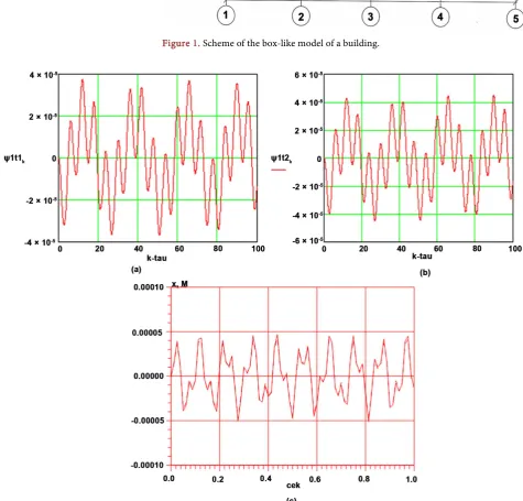
Results obtained with FEM and FDM for the box-like and the continuum plate model of a building are shown in the form of graphs in Figure 2, Figure 3.
Figure 2, Figure 3 show oscillations of characteristic points located at the lev-el of building floors. Solid line characterizes the points at the edge of the floor, and the dashed line—the points at the center of the floor. Under given effects the oscillations of points on the right and left edges of the floor merge.
Figure 2(a) and Figure 2(b) show the displacements of the middle and edge points of the slab on the basis of the plate continuum model of a two-storey building and their values are ψ =1 0.0000374 m and ψ =1 0.0000449 m,
DOI: 10.4236/jamp.2018.69164 1934 Journal of Applied Mathematics and Physics Figure 1. Scheme of the box-like model of a building.
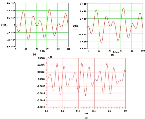
[image:7.595.59.535.231.686.2]DOI: 10.4236/jamp.2018.69164 1935 Journal of Applied Mathematics and Physics Figure 3. Displacements of a five-storey building, obtained at characteristic points, in m (a) is the characteristic point at the middle of the floor, (b) is the characteristic point at the left edge of the floor, (c) is the graph obtained with FEM.
points of the slab on the basis of the box-like model with FEM of a two-storey building and their values are Rmid =0.0000430 m and Redg =0.0000500 m,
respectively.
Comparison of results based on the plotted graphs shows that the values of displacements based on the box-like model with FEM are 10% - 13% less than the results based on the plate continuum model.
Figure 3(a) and Figure 3(b) show the displacements at the middle and edge points of the slab on the basis of the plate continuum model of a five-story building and their values are ψ =1 0.000472 m and ψ =1 0.000496 m,
respec-tively. Figure 3(c) shows the graph of displacements at the middle and edge points of the slab on the basis of the box-like model with FEM of a five-storey building and their values are Rmid =0.000520 m and Redg =0.000550 m.
displace-DOI: 10.4236/jamp.2018.69164 1936 Journal of Applied Mathematics and Physics ments do not differ significantly.
The values of the generalized displacements obtained from the calculations of two-storey and five-story buildings for seismic effects at different points of floor differ within the range of 10%.
5. Conclusion
In conclusion, it should be noted that on the basis of the bimoment theory of thick plates a dynamic plate-like model of the building has been developed, re-flecting its spatial strains. Using the geometry of the building and its rooms, the reduced density, moduli of elasticity and shear of the plate model have been de-termined. The plate model of the building due to the choice of coefficients
22, , , ,33 12 13 23
ξ ξ ξ ξ ξ , adequately reflects the laws of displacements of the points of the building. So, the plate model is acceptable for determining the displacement fields of a tall building during an earthquake and the dynamic characteristics of a building.
Conflicts of Interest
The authors declare no conflicts of interest regarding the publication of this paper.
References
[1] Rashidov, T.R., Shamsiev, U.S., Musheev, R.N. and Bovshover, A.Z. (1992) Seismo-dynamics of Spatial Systems. “Fan”, Tashkent, 152 p.
[2] Abdurashidov, K.S. (1989) Oscillation and Seismic Stability of Industrial Structures. “Fan”, Tashkent, 76 p.
[3] Birbraer, A.N. (1998) Calculation of Structures for Seismic Resistance. Nauka, St. Petersburg, 254 p.
[4] Ramin, K. and Mehrabpour, F. (2014) Study of Short Column Behavior Originating from the Level Difference on Sloping Lots during Earthquake (Special Case: Rein-forced Concrete Buildings). Open Journal of Civil Engineering, USA, 4, 23-34.
https://doi.org/10.4236/ojce.2014.41003
[5] Corchete, V. (2010) The Analysis of Accelerograms for the Earthquake Resistant Design of Structures. International Journal of Geosciences, 32-37.
https://doi.org/10.4236/ijg.2010.11004
[6] Al-Ansari, M.S. (2013) Reliability Index of Tall Buildings in Earthquake Zones. Open Journal of Earthquake Research, 2, 39-46.
https://doi.org/10.4236/ojer.2013.23005
[7] Usarov, M.K., Ayubov, G.T. and Usarov, D.M. (2017) Dynamic Calculation of the Building on the Basis of a Plate Model, Taking into Account the Bimoments. Prob-lems of Mechanics, No. 1, 34-39.
[8] Usarov, M.K. (2015) Bending of Orthotropic Plates with Consideration of Bimo-ments. Engineering and Construction Magazine, №1, 80-90.
[9] Usarov, M.K. (2014) Bimoment Theory of Bending and Oscillation of Thick Ortho-tropic Plates. Bulletin of the NUUz, No. 2/1, 127-132.
[10] Usarov, M.K. (2016) Dynamic Design of Thick Orthotropic Cantilever Plates with Consideration of Bimoments. World Journal of Mechanics, 6, 341-356.