COMPARISON ON THE EFFECT OF REGENERATIVE AND FILM COOLING IN THE HEAT TRANSFER
CHARACTERISTICS OF SEMI CRYOGENIC THRUST CHAMBER
CHANNELS BY USING CFD AND NUMERICAL ANALYSIS
Kerala Technological University, Sree Narayana Institute of Technology, Adoor, Kerala, India
ARTICLE INFO ABSTRACT
In this paper, Computational
thrust chamber cooling characteristics. The scope of the investigation involves the study of effect of regenerative and film cooling on the heat transfer characteristics of coolant cha
pressure based analysis is carried out in this work. The temperature distributions of coolant along the rectangular cooling channel, temperature distributions of copper and stainless steel walls are the main focus of the study. In this s
the thrust chamber and passes through the rectangular cooling channels before it is fed to the injectors.
Copyright © 2016 Sarath Raj. This is an open access article
distribution, and reproduction in any medium, provided the original work is properly cited.
INTRODUCTION
All rocket engines have one problem in common; high energy released by combusted gases. This problem results in high combustion temperatures in the order of 2400K
heat transfer rates (0.8 to160 MW/m2) in thrust chamber and therefore requires special cooling techniques for the engine. Cooling techniques developed to cope with this problem, either singly or in combination, include regenerative, radiati
cooling or transpiration cooling, ablation, arid inert or endothermic heat sinks. To choose the proper cooling technique mission requirements, environmental requirements and operational requirements should be considered. Regenerative cooling is one of the most widely applied cooling techniques used in liquid propellant rocket engines.In this paper CFD modelling and analysis is used for predicting the heat transfer characteristics, considering a rectangular channel of aspect ratio 5. Regenerative cooling of a liquid propellant rocket engine consists of a balance between the energy rejected
*Corresponding author: Sarath Raj,
Kerala Technological University, SreeNarayana Institute of Technology, Adoor, Kerala, India.
ISSN: 0975-833X
Article History:
Received xxxxxxxxxx, 2015 Received in revised form xxxxxxxxxxxxxxxxx, 2015 Accepted xxxxxxxxxx, 2015 Published online xxxxxxx,2016
Citation:Sarath Raj, 2016. “Comparison on the effect of regenerative chamber having rectangular cooling channels by using CFD and numerical analysis
Article History:
Received 19th October, 2015
Received in revised form 22nd November, 2015
Accepted 27th December, 2015
Published online 31st January,2016
Key words:
Computational Fluid Dynamics, Aspect Ratio, Thrust Chamber, Rectangular Cooling Channel, Film Cooling, Regeneratice Cooling.
RESEARCH ARTICLE
COMPARISON ON THE EFFECT OF REGENERATIVE AND FILM COOLING IN THE HEAT TRANSFER
CHARACTERISTICS OF SEMI CRYOGENIC THRUST CHAMBER HAVING RECTANGULAR COOLING
CHANNELS BY USING CFD AND NUMERICAL ANALYSIS
*Sarath Raj
Kerala Technological University, Sree Narayana Institute of Technology, Adoor, Kerala, India
ABSTRACT
In this paper, Computational Fluid Dynamics and Numerical Analysis is used to investigate the rocket thrust chamber cooling characteristics. The scope of the investigation involves the study of effect of regenerative and film cooling on the heat transfer characteristics of coolant cha
pressure based analysis is carried out in this work. The temperature distributions of coolant along the rectangular cooling channel, temperature distributions of copper and stainless steel walls are the main focus of the study. In this study the, the coolant (kerosene), which is the fuel) enters at the aft end of the thrust chamber and passes through the rectangular cooling channels before it is fed to the injectors.
is an open access article distributed under the Creative Commons Attribution License, which distribution, and reproduction in any medium, provided the original work is properly cited.
All rocket engines have one problem in common; high energy released by combusted gases. This problem results in high combustion temperatures in the order of 2400K to 3600 K, high ) in thrust chamber and therefore requires special cooling techniques for the engine. Cooling techniques developed to cope with this problem, either singly or in combination, include regenerative, radiation, film cooling or transpiration cooling, ablation, arid inert or endothermic heat sinks. To choose the proper cooling technique mission requirements, environmental requirements and operational requirements should be considered. e of the most widely applied cooling techniques used in liquid propellant rocket engines.In this paper CFD modelling and analysis is used for predicting the heat transfer characteristics, considering a rectangular channel oling of a liquid propellant rocket engine consists of a balance between the energy rejected
Kerala Technological University, SreeNarayana Institute of
by the combustion of gases and the heat energy absorbed by the coolant. The energy absorbed by the coolant is not wasted; it increases the initial energy content of the propellant prior to injection, increasing the exhaust velocity slightly (0.1 to 1.5%). Therefore thermal energy is recovered in the system. Basically there are three domains in a generatively cooled rocket engine; gas domain (combusted gases), liquid domain (coolant) and the solid domain (thrust chamber wall). Among all the different cooling systems the regenerative is the most efficient along with film cooling. In regenerative cooling, the fluid flows in cooling channels surrounding the thrust chamber; as a consequence the study of flow evolution in the channels becomes important in the case t
and for the system analysis, particularly in the case of closed cycle turbo pump-fed engines. In the cooling channels the propellant can be either in a subcritical or supercritical state depending on its nature and on its therm
Literature review
Mary F. Wadel(1)did an analytical investigation on the effect of high aspect ratio cooling channels, by considering different channel designs, on hot-gas-side wall temperature and coolant
Available online at http://www.journalcra.com
International Journal of Current Research Vol. 8, Issue, 01, pp.25891-25898, January, 2016
INTERNATIONAL
Comparison on the effect of regenerative and film cooling in the heat transfer characteristics of semi cryogenic thrust chamber having rectangular cooling channels by using CFD and numerical analysis”, International Journal of Current Research,
z
COMPARISON ON THE EFFECT OF REGENERATIVE AND FILM COOLING IN THE HEAT TRANSFER
HAVING RECTANGULAR COOLING
CHANNELS BY USING CFD AND NUMERICAL ANALYSIS
Kerala Technological University, Sree Narayana Institute of Technology, Adoor, Kerala, India
Fluid Dynamics and Numerical Analysis is used to investigate the rocket thrust chamber cooling characteristics. The scope of the investigation involves the study of effect of regenerative and film cooling on the heat transfer characteristics of coolant channel. Steady state pressure based analysis is carried out in this work. The temperature distributions of coolant along the rectangular cooling channel, temperature distributions of copper and stainless steel walls are the main tudy the, the coolant (kerosene), which is the fuel) enters at the aft end of the thrust chamber and passes through the rectangular cooling channels before it is fed to the injectors.
ribution License, which permits unrestricted use,
the combustion of gases and the heat energy absorbed by the coolant. The energy absorbed by the coolant is not wasted; it increases the initial energy content of the propellant prior to injection, increasing the exhaust velocity slightly (0.1 to 1.5%).
erefore thermal energy is recovered in the system. Basically there are three domains in a generatively cooled rocket engine; gas domain (combusted gases), liquid domain (coolant) and the solid domain (thrust chamber wall). Among all the different ystems the regenerative is the most efficient along with film cooling. In regenerative cooling, the fluid flows in cooling channels surrounding the thrust chamber; as a consequence the study of flow evolution in the channels becomes important in the case thrust chamber thermal design and for the system analysis, particularly in the case of
closed-fed engines. In the cooling channels the propellant can be either in a subcritical or supercritical state depending on its nature and on its thermo dynamical state.
did an analytical investigation on the effect of high aspect ratio cooling channels, by considering different side wall temperature and coolant
INTERNATIONAL JOURNAL OF CURRENT RESEARCH
and film cooling in the heat transfer characteristics of semi cryogenic thrust
pressure drop for liquid hydrogen cooled rocket combustion chamber. Coolant channel design element considered were; length of combustion chamber in which high aspect ratio (height/width) cooling was applied, number of coolant channels. And coolant channel shape. Daniel K.
Brian Landrum(2) determined the flow field characteristics in a coolant channels by the use of a commercial CFD and metaphysics software developed by CFD Research Crop called CFD-ACE+. The channels are characterized by high Reynolds number, varying aspect ratio, varying curvature, asymmetric and symmetric heating. The supercritical hydrogen is used as coolant for their analysis. Micheal L. Meyer
experiment on a series of electrically heated tube to investigate the effect of high aspect ratio on the curvature heat transfer enhancement in uniformly heated rectangular cooling passages. Three hardware geometry were tested; a base line straight aspect ratio 10 tube, an aspect ratio 1(square) tube with 45o curve, and an aspect ratio 10 tube with a 450 curve. Gaseous nitrogen is used as coolant. Mercleand
discussed the use of detailed CFD modelling for the description of cooling in rocket chambers. The overall analysis includes a complete three-dimensional analysis of the fl
regeneratively cooled passages, conjugate heat transfer in the combustor wall, and the effect of film cooling on the inside chamber. Representative results for the cooling passages are presents showing the effect of heat conduction in the copper walls with tube aspect ratio of 1.5:1.
Problem solving with CFD
In solving fluid flow problems we must be aware that the underlying physics is complex and the results generated by a CFD code are at the best as good as the physics and chemistry embedded in it and at worst as its operator. Prior to setting up and running a simulation using CFD software there is a stage of identification and formulation of the problem in terms of its physical and chemical phenomena that need to be considered. Over 50% of time spent in industry on a CFD project is devoted for defining the domain geometry and for grid generation.
Computational Fluid Dynamics Simulation
The design, scalability, and running of unit operations in chemical process industries rely heavily upon empiricism and correlations of overall variables for non
equilibrium conditions. Many equipment designs in use based on the past experience of experts applying rules of thumb, resembling art more than science. Processes that are sensitive to the local phenomena and the reactant concentrations are often difficult to design or scale up, because the design correlations do not take local effects into account. Non-idealities introduced by scaling up of lab or pilot scale equipment are difficult, if not impossible to predict accurately. Researchers, equipment designers and chemical process engineers are increasingly using computational fluid dynamics (CFD) for analyzing the flow and performance of process equipments, such as chemical reactors, stirred tanks, fluidized beds, cyclones, spray dryers, pipeline arrays, combustion systems, heat exchangers and other equipmen
for in depth analysis of the fluid mechanics, local effects, and
25892 Sarath Raj, Comparison on the effect of regenerative and film cooling in the heat transfer characteristics of semi cryogenic thrust chamber having rectangular cooling channels by using CFD and numerical analysis
hydrogen cooled rocket combustion chamber. Coolant channel design element considered were; length of combustion chamber in which high aspect ratio (height/width) cooling was applied, number of coolant channels. And coolant channel shape. Daniel K. Parris and D. determined the flow field characteristics in a coolant channels by the use of a commercial CFD and metaphysics software developed by CFD Research Crop called The channels are characterized by high Reynolds aspect ratio, varying curvature, asymmetric and symmetric heating. The supercritical hydrogen is used as Meyer (3) conducted an experiment on a series of electrically heated tube to investigate pect ratio on the curvature heat transfer enhancement in uniformly heated rectangular cooling passages. Three hardware geometry were tested; a base line straight aspect ratio 10 tube, an aspect ratio 1(square) tube with 45o be with a 450 curve. Gaseous Mercleand Sankaran (2004) discussed the use of detailed CFD modelling for the description of cooling in rocket chambers. The overall analysis includes a dimensional analysis of the flow in the regeneratively cooled passages, conjugate heat transfer in the combustor wall, and the effect of film cooling on the inside chamber. Representative results for the cooling passages are presents showing the effect of heat conduction in the copper
In solving fluid flow problems we must be aware that the underlying physics is complex and the results generated by a CFD code are at the best as good as the physics and chemistry embedded in it and at worst as its operator. Prior to setting up and running a simulation using CFD software there is a stage of ntification and formulation of the problem in terms of its physical and chemical phenomena that need to be considered. Over 50% of time spent in industry on a CFD project is devoted for defining the domain geometry and for grid
Fluid Dynamics Simulation
The design, scalability, and running of unit operations in chemical process industries rely heavily upon empiricism and correlations of overall variables for ideal or non-equilibrium conditions. Many equipment designs in use are based on the past experience of experts applying rules of thumb, resembling art more than science. Processes that are sensitive to the local phenomena and the reactant concentrations are often difficult to design or scale up, because tions do not take local effects into account. idealities introduced by scaling up of lab or pilot scale equipment are difficult, if not impossible to predict accurately. Researchers, equipment designers and chemical process
using computational fluid dynamics (CFD) for analyzing the flow and performance of process equipments, such as chemical reactors, stirred tanks, fluidized beds, cyclones, spray dryers, pipeline arrays, combustion systems, heat exchangers and other equipments. CFD allows for in depth analysis of the fluid mechanics, local effects, and
chemistry in these types of equipment such as turbulence and combustion. CFD can be used when design correlations or experimental data are not available. It provides comprehens data that are not easily obtainable from experimental tests. It highlights the root cause, not just the effect and many ‘what if’ scenarios can often be analysed in a short time. This method reduces scale-up problems, because the models are based on the fundamental physics and are scale
basically the science of predicting heat transfer, fluid flow, chemical reactions, mass transfer and related phenomena by solving the mathematical equations that govern these processes using numerical algorithm. It is the merger of the classical branches of theoretical and experimental science, with the infusion of modern element of numerical computation. The results of CFD analyses are relevant engineering data used in conceptual studies of new design
redesign. In many cases, CFD results in better insight, better reliability, improved performance, more confident scale improved product consistency, and higher plant productivity. The progress of CFD during the last fifty ye
extraordinary. Much of this progress has been driven by the outstanding increases in digital computing speed. The continual and exponential increase in computing power, also improved the physical models in many CFD codes, and better user interfaces now enables non-experts to use CFD as a design tool on day-to-day basis. As a consequence, CFD has progressed from the domain of mainframe to the high
workstation and even to laptop PCs.
Modelling
For aspect ratio5 channel dimensio
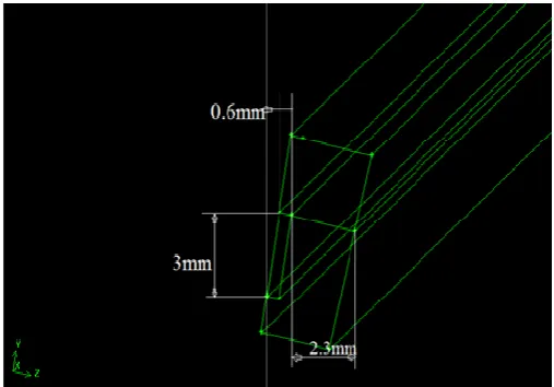
[image:2.595.308.562.446.623.2]is 3mm, width 0.6mm and rib width is 2.3mm
Figure 1. Channel dimensions
Grid generator
GAMBIT 2.4.6 is used for modelling
FLUENT 6.3.26, a pressure based segregated solver, is used for the analysis. Standard k-ε two
employed with standard wall functions. SIMPLE algorithm is used to get the pressure field .The computational do consists of one fluid and two solid domains. The fluid domains
Comparison on the effect of regenerative and film cooling in the heat transfer characteristics of semi cryogenic thrust having rectangular cooling channels by using CFD and numerical analysis
chemistry in these types of equipment such as turbulence and combustion. CFD can be used when design correlations or experimental data are not available. It provides comprehensive data that are not easily obtainable from experimental tests. It highlights the root cause, not just the effect and many ‘what if’ scenarios can often be analysed in a short time. This method up problems, because the models are based on e fundamental physics and are scale-independent.CFD is basically the science of predicting heat transfer, fluid flow, chemical reactions, mass transfer and related phenomena by solving the mathematical equations that govern these processes algorithm. It is the merger of the classical branches of theoretical and experimental science, with the infusion of modern element of numerical computation. The results of CFD analyses are relevant engineering data used in conceptual studies of new designs, product development, and redesign. In many cases, CFD results in better insight, better reliability, improved performance, more confident scale-up, improved product consistency, and higher plant productivity. The progress of CFD during the last fifty years has been extraordinary. Much of this progress has been driven by the outstanding increases in digital computing speed. The continual and exponential increase in computing power, also improved the physical models in many CFD codes, and better user experts to use CFD as a design tool day basis. As a consequence, CFD has progressed from the domain of mainframe to the high-end engineering workstation and even to laptop PCs.
For aspect ratio5 channel dimensions are height of the channel is 3mm, width 0.6mm and rib width is 2.3mm
Channel dimensions
GAMBIT 2.4.6 is used for modelling and grid generation. FLUENT 6.3.26, a pressure based segregated solver, is used for ε two-equation turbulence model is employed with standard wall functions. SIMPLE algorithm is used to get the pressure field .The computational domain consists of one fluid and two solid domains. The fluid domains
include coolant (kerosene) which flows through the rectangular channels provided on the surface. The solid domains include inner copper shell and stainless steel outer covering.
Figure 2. Selected sector with boundary conditions
Comparatively fine structured mesh is adapted for the geometry. Tet/Hybrid elements of TGrid type is used for the volume mesh and for the entire computational domain with the aspect ratio 5 the total number of cells varies from 112800 to 200000. The grid generated is shown below.
flow rate of the kerosene (coolant) through all the channels is 7.57 kg/s and the temperature at the inlet is 300K.Pressure outlet of 1bar is used for the outlet zone of cool
outermost wall of stainless steel covering is assumed to be adiabatic. The lower base copper wall is split into three sections and heat transfer coefficients at each of the section of the base wall is calculated by using Bartz Equation and CEA coding and the heat transfer coefficient thus obtained is applied on the base copper wall as boundary condition.
[image:3.595.38.291.502.647.2]Film Cooling f all the boundary conditions are the same only change is in heat transfer coefficients, which reduces by 70% of the initial value
Figure 3. Grid display of the computational domain, aspect ratio 5
RESULTS AND DISCUSSION
Numerical Analysis
(I) Aspect Ratio 5. (Considering Regenerative cooling)
Equations used Bartz Equation
25893 International Journal of Current Research,
include coolant (kerosene) which flows through the rectangular channels provided on the surface. The solid domains include inner copper shell and stainless steel outer covering.
Selected sector with boundary conditions
Comparatively fine structured mesh is adapted for the geometry. Tet/Hybrid elements of TGrid type is used for the volume mesh and for the entire computational domain with the ls varies from 112800 to 200000. The grid generated is shown below.The total mass flow rate of the kerosene (coolant) through all the channels is 7.57 kg/s and the temperature at the inlet is 300K.Pressure outlet of 1bar is used for the outlet zone of coolant. The outermost wall of stainless steel covering is assumed to be adiabatic. The lower base copper wall is split into three sections and heat transfer coefficients at each of the section of the base wall is calculated by using Bartz Equation and CEA ing and the heat transfer coefficient thus obtained is applied on the base copper wall as boundary condition. In the case of Film Cooling f all the boundary conditions are the same only change is in heat transfer coefficients, which reduces by 70%
Grid display of the computational domain, aspect ratio 5
(I) Aspect Ratio 5. (Considering Regenerative cooling)
. . μ
.
.
Where,
σ = 0.5
1 +
(2)
q
(3)T
= T
γ γ
Where,
= (P )
. For turbulent flows.h
=heat transfer coefficientd
=Throat diameter mμ
=ViscosityC
=specific heat at constant pressureP
=Prandtl numberP
=Chamber pressureT
=Adiabatic wall temperature KT
=Combustion temperature Ki.Chamber Section
Substituting the values of
μ
,hg= 14563.92 W/m2K
Adiabatic wall temperature, by using equation (4) Taw = 3656 K
Heat Flux From equation (3)
qconvective= 43.06468×10⁶ W/m2
ii)THROAT SECTION Substituting the values of equation
hg= 23656.746 W/m 2
K
Adiabatic wall temperature, by using equation (4) Taw = 3491.85 K
Heat Flux
From equation (3) qconvective= 64.05×10
6
W/m2
iii)EXIT SECTION
International Journal of Current Research, Vol. 08, Issue, 01, pp.25891-25898, January, 201
∗
. .
σ (1)
+ 0.5
.1 +
(3)
(4)
For turbulent flows.
=specific heat at constant pressure
=Adiabatic wall temperature K =Combustion temperature K
P
,C
,C
∗ in Bartz equationAdiabatic wall temperature, by using equation (4)
Substituting the values of
μ
,P
,C
,C
∗ in BartzAdiabatic wall temperature, by using equation (4)
Substituting the values of
μ
,P
,C
equationhg= 4821.287 W/m 2
K
Adiabatic wall temperature Taw, by using equation (4)
Taw = 5786.89 K
Heat Flux From equation (3)
qconvective= 25.4896×10⁶W/m2
(II) Aspect Ratio 5. (Considering Film cooling)
i.Chamber SECTION
Substituting the values of
μ
,P
,C
,C
∗. Heat transfer coefficient at the chamber sectionh
=10194.744
W
m K
Adiabatic wall temperature, by using equation (4) Taw = 3656 K
Heat Flux From equation (3) qconvective= 31.4102×10
6
W/m2
ii)THROAT SECTION
Substituting the values of
μ
,P
,C
,C
∗ hg =16559.7222W
m K
Adiabatic wall temperature, by using equation (4) Taw = 3491.85 K
Heat Flux From equation (3) qconvective= 46.48065×10
6
W/m2
iii)EXIT SECTION
Substituting the values of
μ
,P
,C
equationhg= 3374.9009W/m2K
Figure 4. Three-dimensional schematic of computational domain and converged contour for total temperature
25894 Sarath Raj, Comparison on the effect of regenerative and film cooling in the heat transfer characteristics of semi cryogenic thrust chamber having rectangular cooling channels by using CFD and numerical analysis
C
,C
∗ in Bartz, by using equation (4)
(II) Aspect Ratio 5. (Considering Film cooling)
∗ in Bartz equation
. Heat transfer coefficient at the chamber sectionhg
using equation (4)
in Bartz equation
Adiabatic wall temperature, by using equation (4)
C
,C
∗ in BartzAdiabatic wall temperature Taw
Taw = 5786.89 K
Heat Flux From equation (3)
qconvective= 18.1802×10⁶W/m2
B. CFD Analysis
(I) Aspect Ratio 5. (Considering Regenerative cooling)
The temperature distributions of coolant along the coolant channel, temperature distributions of copper and stainless steel walls are the main focus of the study.
channel with aspect ratio 5 the, the coolant(kerosene ,which is the fuel) enters at the aft end of the thrust chamber and passes through the rectangular cooling channels before it is fed to the injectors,(Single regenerative circuit). The following are the results obtained in the analysis.
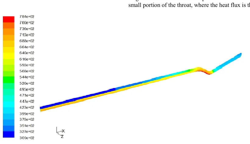
dimensional schematic of computational domain In this the total temperature varies from 300, at the end of the divergent section to a maximum of 784K at the upstream of the throat, which is well below the melting point of copper and stainless steel. Figure 5 shows the base copper wall temperature variation along the length of the thrust chamber. The maximum temperature 784K is observed at the throat section which is well below the melting point of th
hydrocarbon based fuels like kerosene as in the present case, there is always the chance of solid deposits inside the walls, if the wall temperature exceeds the coking limit. So it is important to investigate the coolant temperatur
enthalpy, coolant velocity and hot gas and coolant side wall temperatures to obtain the effectiveness of the cooling circuit. Figure 7 shows the coolant domain inside the rectangular channel. It is clear that coolant enters into the channel at temperature of 300K and is heated up to a maximum temperature of 510K which is well below the coking temperature of kerosene. Generally coking temperature for RP ranges from 561-727K. The slope of the line is an indication of the amount of heat absorbed b
length of the section. The slope is almost constant, except for small portion of the throat, where the heat flux is the maximum.
dimensional schematic of computational domain and converged contour for total temperature
on the effect of regenerative and film cooling in the heat transfer characteristics of semi cryogenic thrust chamber having rectangular cooling channels by using CFD and numerical analysis
aw, by using equation (4)
(I) Aspect Ratio 5. (Considering Regenerative cooling)
The temperature distributions of coolant along the coolant channel, temperature distributions of copper and stainless steel walls are the main focus of the study. For the rectangular the, the coolant(kerosene ,which is the fuel) enters at the aft end of the thrust chamber and passes through the rectangular cooling channels before it is fed to the injectors,(Single regenerative circuit). The following are the esults obtained in the analysis. Figure 4 shows the three-dimensional schematic of computational domain In this the total temperature varies from 300, at the end of the divergent section to a maximum of 784K at the upstream of the throat, ow the melting point of copper and stainless Figure 5 shows the base copper wall temperature variation along the length of the thrust chamber. The maximum temperature 784K is observed at the throat section which is well below the melting point of the Copper. In the case of hydrocarbon based fuels like kerosene as in the present case, there is always the chance of solid deposits inside the walls, if the wall temperature exceeds the coking limit. So it is important to investigate the coolant temperature, coolant enthalpy, coolant velocity and hot gas and coolant side wall temperatures to obtain the effectiveness of the cooling circuit. Figure 7 shows the coolant domain inside the rectangular channel. It is clear that coolant enters into the channel at emperature of 300K and is heated up to a maximum temperature of 510K which is well below the coking temperature of kerosene. Generally coking temperature for RP-1 727K. The slope of the line is an indication of the amount of heat absorbed by the coolant along the axial length of the section. The slope is almost constant, except for small portion of the throat, where the heat flux is the maximum.
dimensional schematic of computational domain and converged contour for total temperature
[image:4.595.95.506.523.760.2]Figure 5
Figure 7.
25895 International Journal of Current Research,
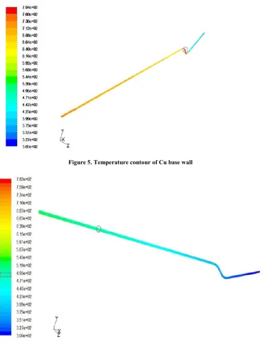
[image:5.595.133.467.585.784.2]Figure 5. Temperature contour of Cu base wall
Figure 6. Contour of coolant temperature
Figure 7. Coolant temperature distributions
Figure 8
Figure 9.
Figure 10. Three-dimensional schematic of computational domain and converged contour for total temperature for
[image:6.595.106.483.303.522.2]25896 Sarath Raj, Comparison on the effect of regenerative and film cooling in the heat transfer characteristics of semi cryogenic thrust chamber having rectangular cooling channels by using CFD and numerical analysis
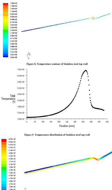
Figure 8. Temperature contour of Stainless steel top wall
Figure 9. Temperature distribution of Stainless steel top wall
dimensional schematic of computational domain and converged contour for total temperature for Aspect Ratio 5 with film cooling
the effect of regenerative and film cooling in the heat transfer characteristics of semi cryogenic thrust chamber having rectangular cooling channels by using CFD and numerical analysis
dimensional schematic of computational domain and converged contour for total temperature for
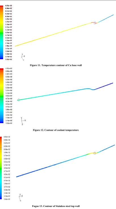
Figure 11. Temperature contour of Cu base wall
Figure 12. Contour of coolant temperature
Fugue 13. Contour of Stainless steel top wall
The reason for the smooth increase of the coolant temperature along the cooling channel is the overall heat flow (product of heat flux and area) remains constant. Figure 9 shows the temperature distribution for stainless steel top wall along the thrust chamber length and the maximum temperature is 687K which is well below the melting point of steel.
(II) Aspect Ratio 5. (Considering Film cooling)
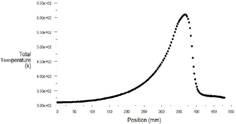
From the Figure. 10 it is clear that by considering film cooling the maximum temperature limited to 685K that is there is 14% reduction in overall total temperature as compared to regenerative cooling this is because the secondary film coolant will act as a temperature barrier. Figure 11.shows the temperature distibution of base Cu wall with filmcooling. It is clear that the maximum teperature of copper reaches upto 685K which is below the melting point and so in allowable temperature limit. Figure 12. shows the temperature distribution of coolant domain inside the rectangular channel. From the figure it is clear that after cooling the temperature reaches between 454K and 473K which is below the coking temperature of kerosene.
Conclusion
The effectiveness of regenerative cooling of thrust chamber is carried out by considering aspect ratio 5. Regenerative and Film cooling studies show that the wall temperatures are decreasing down into acceptable material limit at the hot gas side. Coolant temperature and coolant velocity are also shown to be in the acceptable region. The analysis shows that coolant side wall temperature tends to exceed the coking limit at the throat region.
This may lead to the deposition of solid deposits within the coolant channels since kerosene, which is a hydrocarbon based fuel is used as the coolant. But by adopting sub cooling and increasing the aspect ratio of the coolant channels, reduced the coolant side wall temperature below the coking limit and hence it avoids the likelihood of coking in the coolant channel
Acknowledgment
The authors thank the Managing Director Sree Narayana Institute of Technology Adoor, for giving the financial assistance and Head of the Department, Mechanical Engineering Sree Narayana Institute of Technology Adoor, for giving valuable guidance and suggestions.
REFERENCES
Daniel K.Parris and D. Brian Landrum, “Regenerative Cooling for Liquid rocket Engines”, Journal of Thermal Science, Vol.4, No.1, pp. 54-59.
Mary F. Wadel, “Heat Transfer in Rocket Combustion chambers”, N 94-20041, SECA.Vol.2,pp 99-108.
MerkleC. L., D. Li and V. Sankaran, “Analysis of Regen Cooling in combustion Chambers”, NASA Space Act Agreement, NCC8-200.
MichealL.Meyer, “Advanced Rocket Engines”,AIAA-2004, NATO OTAN- 74239.
[image:8.595.90.501.53.268.2]*******
Figure 14. Temperature distribution of Stainless steel top wall. The temperature disribution of stainless steel outer wall and the maximum temperature is 628K