Abstract— JPEG2000 has become one of the most rewarding image coding standards. It provides a practical set of features which weren’t necessarily available in the previous still image coding standards. The features were realized as a result of two new techniques adopted in this standard, namely the Discrete Wavelet Transform (DWT), and Embedded Block Coding with Optimized Truncation (EBCOT). The generated coefficients by DWT are entropy coded by EBCOT algorithm. EBCOT is a two-tiered coder, where Tier-1 is a context-based adaptive arithmetic coder, and Tier-2 is a rate control algorithm. The complexity of EBCOT Tier-1 makes its hardware implementations very difficult. A high speed hardware implementation usually takes a large amount of space on the die.
In this paper we propose a new simplified pipelined architecture for the JPEG2000 MQ-Coder. The proposed approach has resulted in a 20% decrease in hardware requirements and 10% increase in clock frequency. Post synthesis simulations indicate that the proposed architecture is able to compress 4 CIF video (704×576 pixels) at a rate of 30 frames per second, making it a good candidate for high resolution real time video coding, or high speed compression of high resolution images.
Index Terms— Byte-out, CODELPS, CODEMPS, EBCOT, flush, JPEG2000, MQ-Coder, Renormalization, Tile-Component
I. INTRODUCTION
mage data compression has always been a necessary and prominent issue due to boundaries of data bandwidth and storage. JPEG [1][2], a traditional standard of coding, has proved to be a suitable technique for compressing natural images at high bit rates. Yet the imperfections due to the blocking effect make this technique impractical especially for low bit rates of image compression.
JPEG2000 [3]-[8] has recently been proposed as a new high performance and multi-featured, yet complex standard of digital image coding. JPEG2000 offers numerous advantages over JPEG. These advantages include: ROI (Region Of Interest) coding, quality vs. resolution compression, lossless and lossy compression, progressive image compression/transmission by resolution/quality, random code-stream access and error resilience. Such characteristics add to the functionality of a system that is
M. Ahmadvand is with the Department of Computer Engineering & IT, Hamedan University of Technology, Hamedan, Iran (e-mail: [email protected]).
A. Ezhdehakosh is with Department of Computer Engineering & IT, Amirkabir University of Technology, Tehran, Iran (e-mail: [email protected]).
employing JPEG2000 as an image compression technique. The features and performance of JPEG2000 make this standard superior to JPEG. Yet computational complexities of JPEG2000 are much higher than that of JPEG. Such complexities are due to EBCOT [9][10] as the most important algorithm employed in JPEG2000. That is why EBCOT algorithm plays a major role in hardware implementation of JPEG2000 in different applications.
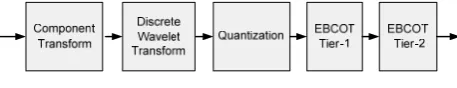
[image:1.595.311.540.342.386.2]During the process of encoding, an image is partitioned into data matrices called components. Each Tile-component is then coded separately. The process of coding is made up of different sections. These sections are depicted in Figure 1 and each is described below.
Fig. 1. JPEG2000 encoder block diagram
A. Component Transform
This section is optional in JPEG2000 and is used to improve compression efficiency [11]. The transform converts the RGB data into another color representation, with a luminance (or intensity) channel and two color difference channels. This is used for taking advantage of some of the redundancy between the original RGB components. In particular color difference components mostly account for less than 20% of the bits used to compress a color image; therefore they are better represented as individual components [4].
B. Discrete Wavelet Transform (DWT)
DWT [4] is a domain transform that transforms an image Tile-component from special domain to frequency domain and provides a special decorrelation. This transform can be executed for as many levels as necessary. The output of each level of DWT is categorized into four sub-bands. Each sub-band contains the high/low frequency characteristics of the input image.
C. Quantization
Quantization [3] is the process by which the sub-band samples generated by the DWT are mapped onto quantization indices for coding. This process is lossy unless the quantization step is one and the coefficients are integer. D. EBCOT Tier-1
This section receives the quantized wavelet coefficients and encodes them into bit-streams. These coefficients are sliced into code-blocks before they are fed into the EBCOT Tier-1 [9][10]. EBCOT Tier-1 is composed of two parts:
A New Pipelined Architecture for JPEG2000
MQ-Coder
M. Ahmadvand, and A. Ezhdehakosh
Bit-Modeler and MQ-Coder [4]. Bit-Modeler is a bit-plane (a matrix that contains all the bits of the same order of all the coefficients of a code block) coder. A Bit-Modeler exploits the symmetries and redundancies within and across the bit-planes and generates corresponding contexts for each bit. After the context is generated, the MQ-Coder will code the bits (decisions) based on their associated contexts. The MQ-Coder is a derivative of Q-Coder [12] and generates compressed bit-streams for every code-block. The detail functionality of MQ-Coder is explained in Section II. E. EBCOT Tier-2
This tier is for rate allocation. The rate allocation is responsible for acquiring the highest quality for the output while maintaining a predetermined resolution, or acquiring the highest resolution while maintaining a predetermined image quality. At EBCOT Tier-2 [3] the bit-streams generated by the Tier-1 is collected with their rate-distortion information. Then different truncation points are set according to the optimization diagram. Each truncation point determines how many bits of a relevant bit-stream are to be selected for the final bit-stream.
TABLEI
RUN TIME PERCENTAGE OF DIFFERENT MODULES IN JPEG2000ENCODER
Operation Lossy Lossless Component Transform 10.1 3.64
DWT 25.14 10.41
Quantization 6.4 N.A. EBCOT Tier-1 44.86 67.35 EBCOT Tier-2 13.5 18.6
The execution time of different modules in the JPEG2000 algorithm is presented in Table I. It is noted from this table that EBCOT algorithm, as one of the main modules in JPEG2000 standard, occupies over half of the execution time of the whole procedure. It is also noted that the complexity weight of EBCOT lies within Tier-1. Therefore, the architectures proposed to reduce hardware resources of Tier-1 while maintaining a high throughput, are highly valued.
In this paper we propose a novel pipelined architecture for JPEG2000 MQ-Coder. In our proposed architecture we have focused on reducing the hardware resources while securing a high throughput for the design. Our main contribution in this design is a special trade-off between area and execution time.
This paper is organized at follows: in the next section a deep analysis of the MQ-Coder will be presented. In section III the proposed architecture for the MQ-Coder are reviewed. Our proposed architecture is presented at section IV. Synthesis results are depicted in section V followed by conclusions and references.
II. MQ-CODER ALGORITHMS AND ANALYSIS
MQ-Coder is a module applied in JPEG2000 EBCOT Tier-1 for generating output bit-streams [3][4][9]. MQ-Coder is an adaptive Binary Arithmetic MQ-Coder (BAC). The functionality of BAC is discussed in the following sub-section.
A. Binary Arithmetic Coder (BAC)
In BAC [13], symbols (either logic '0' or logic '1') in a code-stream are classified as either More Probable Symbol (MPS) or Less Probable Symbol (LPS) [13]. The probability of the occurrence of the MPS is called Pe and the probability of the occurrence of LPS is called Qe. Either of the symbols 0 or 1 can be MPS or LPS depending on the probability of their occurrence. In BAC an interval is considered in order to represent the probability of MPS and LPS. The initial interval is [0,1) and is divided to subintervals corresponding to the values of Qe and Pe. When a symbol occurs (either MPS or LPS), the subinterval associated with that symbol becomes the new interval. When the last symbol has been received a code-word C will be developed. The code-word C always points to the left point (lower bound) of the interval and A denotes its width.
The BAC algorithm needs multiplication for the coding of each symbol, which is an area and time consuming operation for hardware implementation. Also, since a compressed data will only be generated when the last symbol of an input stream has been received by the encoder, an implementation of this algorithm will be exposed to serious loss of data at the times that the last bit of a stream is not received. Finally, after each update the length of the code-word and interval will be grown. This leads to a need for a high number of bits for storing the code-word and interval in hardware implementation of the algorithm. A specific type of efficient BAC which has been adapted to deal with the issues discussed above has been developed and is called MQ-Coder.
B. MQ-Coder
This adaptive binary arithmetic coder is used in JPEG2000 standard. In order to omit the multiplication operations, the length of interval A is maintained in the range [0.75,1.5). This means that the interval is always approximately equal to 1, if rounding to one significant bit. Therefore Qe ×A ≈ Qe and the following changes will be made to step 3 of the encoding process of BAC. MPS occurrence: C = C + Qe and A = A – Qe. LPS occurrence: A = Qe. The value C is kept in a 32 bit code-word [3][4] as shown in Figure 2.
0000 cbbb bbbb bsss xxxx xxxx xxxx xxxx
31…….28 27…...24 23…….20 19…....16 15…..12 11…….8 7…….4 3……..0
Fig. 2. Code-word partitions
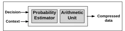
In MQ-Coder, the last byte of the code-word is being sent to the output at special times, therefore the problems associated with the growing length of a code-word and compressed data being generated only after receiving the code-word's last bit is removed. The MQ-Coder can be understood as a module illustrated in Figure 3, which maps a sequence of input symbols (decisions) and associated contexts, to a single compressed code-word.
algorithm is performed, while if an LPS has occurred the CODELPS algorithm is performed.
Probability Estimator
Arithmetic Unit
Decision Context
[image:3.595.52.269.79.134.2]Compressed data
Fig. 3. MQ-Coder block diagram
1. CODEMPS Algorithm
If an MPS has occurred, the CODEMPS procedure [3] is called. The length of interval A is updated to (A – Qe) and code-word C is updated to (C + Qe). The value of A is always checked after it has been updated to determine if it has fallen below 0.75. If it does, it could mean that (A – Qe) has fallen below the value of Qe meaning that the subinterval associated with MPS is smaller than the subinterval associated with LPS. Therefore the two subintervals must be changed.
2. CODELPS Algorithm
If an LPS has occurred, the CODELPS procedure [3] is called. The length of the interval A is updated to value Qe, while the code-word C remains unchanged. If the LPS occurs successively for many times, Qe would become progressively larger and eventually (A – Qe) would become less than Qe. Therefore the portion of interval A that represents probability associated with LPS would become larger than the portion representing the probability of MPS. However, this does not occur since the CODELPS procedure tests for this condition and swaps the intervals associated with LPS and MPS when necessary.
3. Renormalization Algorithm
In order to ensure that the interval value A always remains in the range of [0.75,1.5), a renormalization [3] method is applied. The value A would fall below the value of 0.75 at the times that so many MPS has occurred. This case is also true for every time that an LPS occurs. This is due the fact that the value Qe, which interval A is updated to, is always less than 0.75. The renormalization algorithm shifts the values of A and C every time it is applied. The value of C code-word is sent to the output as compressed data by the byte-out and flush algorithms. These algorithms are discussed in the following sub-sections.
4. Byte-out Algorithm
The byte-out algorithm [3] generates the current byte-out value regarding the value of the last byte-out and carry bit in the code-word. As it was mentioned before the value of C is added with the Qe value each time a new decision has been received and value of C has been changed. If a carry bit (bit 'c' in C code-word) is generated from this addition, it must be added to the last generated byte-out. If the last byte-out becomes 0xFF, the carry bit is sent individually along with the last byte-out in order to prevent further carry propagation. This is called bit-stuffing.
5. Flush Algorithm
The flush algorithm is composed of different parts. At first a set-bit algorithm is performed in order to detect the
best value of C, so that the lower two bytes of C contains 16 or 15 bits with the value of 1. After the set-bit algorithm [3], the byte-out algorithm is called for two times. At the end, the last compressed data is checked whether it is 0xFF or not. If it is, nothing is sent to the output since the 0xFF are not sent as the encoded data.
The complexity of the different algorithms in MQ-Coder, make its implementation very difficult. Some challenges encountered in the implementation of these algorithms are as follows:
1. The encoding procedures are serial processes with high dependency. Therefore it is impossible to employ parallel processing in the implementation of these procedures.
2. Renormalization is a time consuming process, which is due to the sequential shifts that are employed in this algorithm. Therefore a novel technique for reducing the execution time of this process is necessary for hardware implementation.
3. A large number of calculations are applied for each context-decision input. This leads to a long execution time and too many resources in hardware implementation.
In order to achieve a good hardware implementation of the MQ-Coder, one must take the aforementioned challenges into consideration.
III. PREVIOUSLY PROPOSED ARCHITECTURES
In this section the hardware implementation of different architectures are compared. Several MQ-Coder implementations have been introduced in the literature. These implementations were using either pipelined or non-pipelined architectures.
Non-pipelined architectures [14] suffer from a low clock frequency and a very low throughput. Several buffers are required for interfacing such architectures with the rest of the components and in order to match their low throughput. This not only affects the overall performance but also increases the hardware resource requirements.
Pipelined architectures consist of a sequence of pipeline stages. The architecture proposed in [15] consists of three stages. The first stage calculates the new interval and code-word results. In order to perform these operations the Qe value and other necessary information such as NMPS will be derived from FSM [3][4]. The renormalization algorithm is also performed in this stage. The second stage is dedicated to the bit-stuffing algorithm. At the third stage four FIFO modules are used. The intricacy of the first stage leads to a critical path that affects the clock frequency. In this design there is no mechanism to prevent data hazards. Since data hazards occur quite often during an adaptive binary arithmetic coding process, the proposed architecture suffers from a large number of pipeline stalls. The flush algorithm is not supported in this design.
performed. The renormalization algorithm is also fulfilled in this stage. Each shift applied in the renormalization algorithm takes one clock cycle in this design. The calculation and renormalization of code-word C is applied in the last pipeline stage. The compressed data is issued from this stage to the output.
In this design, a multi-port memory is used. This leads to an implementation that occupies a large area, and has a slow access time. Besides, as the renormalization algorithm is not implemented with a barrel shifter, there is more chance for pipeline stalls. The flush algorithm is not supported in this design either.
The proposed architecture proposed in [18] is composed of four pipeline stages. At the first stage the probability model is implemented and the state of each context is stored. The main function of stage two is to update the interval value. The renormalization algorithm is also performed in this stage. The update and renormalization of the 16 lower bits of the C code-word, is done in this stage. The rest of the bits in C is updated and renormalized at the last stage. This is done in order to shorten the critical path. The flush and byte-out algorithms are also performed at the last stage.
This design suffers from the slow access time and large area consumption caused by employing a multi-port memory. The renormalization algorithm is not implemented with a barrel shifter, which adds to the chance of receiving pipeline stalls.
The architecture proposed in [19] is a five pipelined stage. The states of contexts are stored at the first stage. The probability model is implemented at stage. The update and renormalization of interval value is performed at the third stage. The code-word C is updated and renormalized at the fourth stage. At the last stage the byte-out and bit-stuffing algorithms are implemented.
The design has balanced stages and no stalls. But this has consumed a lot of hardware resources which in turn has lead to large area consumption. The complexity of this design is mostly caused by the attempt to eliminate pipeline stalls. The flush algorithm is not supported in this design either.
The observed imperfections in the proposed architectures were: unbalanced pipeline stages, not supporting all the algorithms present in the MQ-Coder, lack of solution for removing data hazards, high area consumption and inefficient implementation for the renormalization algorithm. We must note that each one of the proposed architectures has some of the defects mentioned above.
IV. PROPOSED ARCHITECTURE
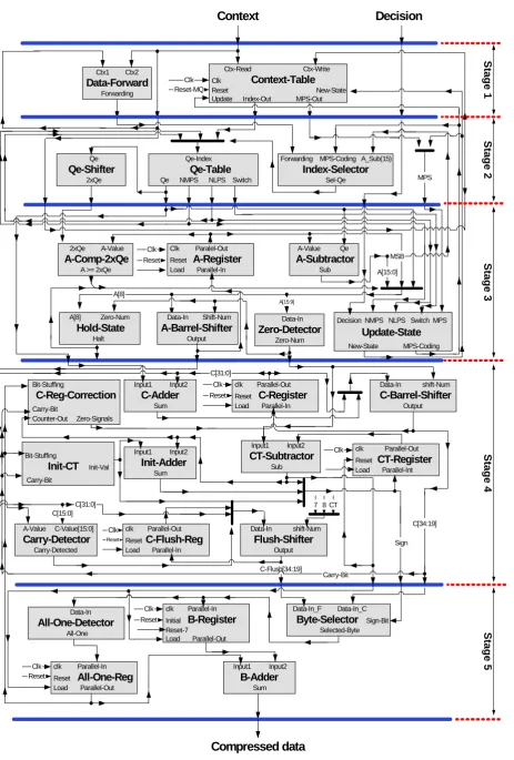
Our proposed architecture consists of five pipeline stages as shown in Figure 4. These stages are as follows: 1) Context-Decision Fetch with data-Forwarding (CDFF), 2) Probability Estimation (PE), 3) Interval Update (IU), 4) Code-word Update (CU) and 5) Byte-Out (BO). Each stage is described in details below.
A. Context-Decision Fetch with data-Forwarding (CDFF) This is the first stage (Figure 4.a.) of our pipelined architecture. The inputs of this stage are a 5-bit context value (ctx-read) along with a single bit decision signal
(decision). The duty of this stage is to generate the state of input value ctx-read. The state includes index of Qe table (look-up table that represents the probability model) and MPS sense [4]. This is done through a Context-Table module that contains a state value for every context. These state values are updated through a feedback context called ctx-write. The current state of the signal ctx-write is updated to new-state which is provided by the next stages. In case that two similar context values are fed to this stage consecutively, the new-state signal is saved and sent to the state output of this stage directly, thus avoiding pipelined stalls. Detecting such cases is done by a Data-Forward-detector module that compares the values of two consecutive contexts.
B. Probability Estimation (PE)
The main module of this stage (Figure 4.b.) is Qe-Table [3] which in fact represents the probability model. Each entry of this table contains probability value (Qe), new index in the case of MPS or LPS occurrence (NMPS and NLPS) and switch (SW) signal [3]. The normal practice in pipeline architectures is to employ a multi-port memory in order to implement the Qe-table. However, our design utilizes a special technique in order to replace the multi-port memory with a single port memory. In this technique the NMPS and NLPS value corresponding to the last context are always stored. In order to handle the data-hazard situation, the index of the current context or the NMPS or the NLPS of the last context is used as the correct index of the current context. It must be noted that cases in which data-hazard occurs are detected by the data-forward-detector in the previous stage. Whether the index of the current context or the NMPS/NLPS of the last context is selected, is done by a module named index-selector. By utilizing this technique the design has removed the pipeline stalls of this stage with minimum hardware overhead. C. Interval Update (IU)
The main task of this stage (Figure 4.c.) is to update the interval length (A) of MQ-Coder. This interval is stored in a 16-bit register called A-Register. In order to update the A value to A – Qe, a 16-bit subtractor is employed. The output of the subtractor is multiplexed with Qe-value and is passed to Zero-Detector and A-Barrel-Shifter as a new interval length. The Zero-Detector module detects the number of consecutive zero bits at most significant positions of this new interval length (Zero-Num). The Zero-Num value is the number of shifts required for the renormalization algorithm and is passed to A-Barrel-Shifter and to the next stage. The new interval length is shifted by the A-Barrel-Shifter in a single clock cycle. The shifted value is stored in A-Register as the renormalized interval length. The normal practice in pipelined architectures is to implement hardware for a maximum of 15 shifts and dedicate one clock cycle per each shift. This results in pipeline stalls equal to the number of shifts. In our architecture the shift is performed by A-Barrel-Shifter and therefore avoiding extra clock cycles.
Ctx-Read Ctx-Write Clk Context-Table Reset New-State Update Index-Out MPS-Out Clk
Reset-MQ Ctx1 Ctx2
Data-Forward
Forwarding
Qe-Index
Qe-Table
Qe NMPS NLPS Switch
Forwarding MPS-Coding A_Sub(15)
Index-Selector
Sel-Qe
Qe
Qe-Shifter
2xQe MPS
2xQe A-Value
A-Comp-2xQe
A >= 2xQe
Clk Paralel-Out Reset A-Register Load Parallel-In
A-Value Qe
A-Subtractor
Sub A[15:0] MSB
Data-In
Zero-Detector
Zero-Num Data-In Shift-Num
A-Barrel-Shifter
Output A[8] Zero-Num
Hold-State
Halt A[8]
Clk Reset
clk Parallel-Out Reset C-Register Load Parallel-In Input1 Input2
C-Adder Sum
Data-In shift-Num C-Barrel-Shifter Output Clk
Reset C[31:0]
A[15:9]
Decision NMPS NLPS Switch MPS
Update-State
New-State MPS-Coding
Input1 Input2 Init-Adder Sum
clk Parallel-Out Reset CT-Register Load Parallel-Int Clk
Input1 Input2
CT-Subtractor
Sub Bit-Stuffing
Init-CT Init-Val Carry-Bit
Bit-Stuffing
C-Reg-Correction
Carry-Bit
Counter-Out Zero-Signals
Data-In shift-Num Flush-Shifter Output A-Value C-Value[15:0]
Carry-Detector
Carry-Detected C[15:0]
C[31:0]
clk Parallel-Out Reset C-Flush-Reg Load Parallel-In
Reset
C-Flush[34:19]
C[34:19] 7 8 CT
Carry-Bit
Sign
Data-In_F Data-In_C Byte-Selector Sign-Bit Selected-Byte clk Parallel-In
Initial B-Register Reset-7
Load Parallel-Out Clk
Reset Data-In
All-One-Detector All-One
Input1 Input2 B-Adder Sum clk Parallel-In
Reset All-One-Reg Load Parallel-Out Clk
Reset
Compressed data Clk
(b) PE
(c) IU
(d) CU
(e) BO
Context Decision
Stage 1
S
tage 2
Stage 5
Stage 3
Stage 4
[image:5.595.63.527.45.731.2](a) CDFF
Renormalization occurrence
[image:6.595.59.260.55.188.2]79%
Fig. 5. Renormalization occurrence probability
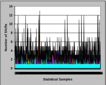
the maximum number of shifts applied for each renormalization is equal to 15, yet as the simulations results presented in Figure 6 indicate, the number of shifts is less than 8 for more than 90% of the time. In our design in order to reduce hardware resources and increase clock frequency, we propose that a maximum of 7 shifts per clock cycle be implemented. A Hold-State module is employed in order to extend the shifting operations for one more clock cycle at the times that the number of shifts is more than 7. This will result in one clock stall in 7.9% of condition in total.
0 2 4 6 8 10 12 14
123456789101112131415161718192021222324252627282930313233343536373839404142434445464748495051525354555657585960616263646566676870697172737475767778798081838284858687888990919293949596100989799101102103104105106107108109110111112113114115116117118119120121122123124125126127128129130132131133134135136137138139140141142143144145146147148149150151152153154155156157158159160162161163164165166167168169170171172173174175177176178179180181182183184185186187188189190191192194193195196197198199200201202203204205206207209208210211212213214215216217218219220221222223224225226227228229230231232233234235236237238239241240242243244245246247248249250251252253254255 Statistical Samples
N
u
m
b
e
r o
f
S
h
ifts
Fig. 6. Number of shifts for various renormalizations
Another module in this stage is the Update-State unit which is used to update new state of current context and also determines if decision is MPS or LPS. The outputs of this module are sent to the context-table of stage 1 as ctx-write and new-state.
A. Code-word Update (CU)
The updating of code-word value is performed in this stage (Figure 4.d.). The code-word value (C) is stored in a 32-bit register called C-Register. The number of shifts that should be performed over the A value and C code-word before every byte-out is stored in a 4-bit register called Register. It should be mentioned that every time the CT-Register becomes zero a byte-out is sent to the next stage. After every byte-out this register is initialized to the value determined by the Init-CT. In order to update the CT-Register a 4-bit subtractor called A-subtractor is used to reduce the CT-Register by Zero-Num. Normally the output of the A-subtractor is positive. Yet in some occasions when CT-Register is less than Zero-Num the result becomes negative. In order to correct this, a 4-bit adder called Init-Adder is employed.
In order to generate the new code-word and therefore
perform the renormalization algorithm, the C + Qe value and the current code-word are multiplexed and the result is passed to the C-Barrel-Shifter. The number of shifts applied in the C-Barrel-Shifter is equal to the number of shifts applied to the A-value in the previous stage.
In the standard the shift operation for the code-word value is introduced so that each shift is performed at every clock cycle. The byte-out data is generated when enough shifts have been performed over the C code-word. The rest of the shift operations are applied after byte-out generation. However, since the shift operations are performed with a barrel shifter in our proposed architecture, the byte-out is produced after all the shifts are applied together. A C-Reg-Correction module is employed in order to recognize the correct location of the byte-out data in the C code-word.
The flush algorithm [3] is performed parallel to the updating and renormalization of the code-word. This algorithm is responsible for sending the last value of C-Register to the output in the end of coding. The suitable C value for best compression is the one that contains the most number of bits with the value 1. The Carry-Detector is employed in order to choose the suitable C value. This value is kept in a register called C-Flush-Reg. When the best value for C is stored, it must be shifted out in order to generate compressed data. This is done by the Flush-Shifter module.
B. Byte-Out (BO)
This stage (Figure 4.e.) performs the byte-out and Bit-stuffing algorithm [3]. An 8-bit register, B-Register, is used to store the last byte of compressed data. The last byte-out for the next clock is selected from the C-Register/C-Flush-Reg by the Byte-Selector module.
In order to implement the Bit-stuffing algorithm two modules are used: The All-One-Detector that determines whether the last byte-out is 0xFF or not and the B-Adder that adds the B–Register value with the value determined by All-One-Detector, namely the carry bit (27th bit of the code-word). The output of the B-Adder is sent to the output of this stage as the compressed data.
V. EXPERIMENTAL RESULTS
The proposed architecture of MQ-Coder has been simulated using VHDL. This architecture is implemented by 0.18 μm CMOS technology. The synthesis results of the proposed architecture are shown in Table II. The gate count and clock frequency of this architecture is compared to three previous pipeline architectures with the same technology. The execution time of our proposed architecture is compared to other architectures at Table III using Lena, Baboon and Jet images with the resolution of 256 × 256 and 24-bit RGB components.
[image:6.595.82.265.344.489.2]TABLEII
COMPARISON OF IMPLEMENTATION RESULT
[15] [16] [19] Proposed
Gate# 8459 7100 9156 7325
Clock Frequency (MHz)
185.5 206.2 190.6 208.1
The architecture in [18][19] does not have a high clock frequency, but since the number of clock cycles for the encoding process is very low, therefore the coding time is acceptable. The only shortcoming of this design is its high number of gate count. In our proposed architecture although the number of clock cycles for an encoding process is higher than the architecture in [19], but due to its high clock frequency it has the lowest coding time. In addition the gate count of our proposed architecture is 20% lower than the next fastest design.
TABLEIII
EXECUTION TIME FOR THREE PICTURES
Timing Lena Baboon Jet
[15] CLK # 1311233 1554195 1286333
Time (ms) 7.1 8.38 6.94
[16] CLK # 1297355 1605745 1276743
Time (ms) 6.29 7.79 6.19
[19] CLK # 998967 1224958 959033
Time (ms) 5.24 6.42 5.03
Our
CLK # 1077885 1321729 1034796
Time (ms) 5.18 6.35 4.98
Post synthesis simulations indicate that the proposed architecture encodes precisely one context-decision pair every 1.079 clock cycle and operates at 208 MHz. This architecture is able to compress 4 CIF video (704×576 pixels) at a rate of 30 frames per second, making it a good candidate for high resolution real time video coding, or high speed compression of high resolution images.
VI. CONCLUSION
A high-speed pipelined architecture with reduced area for JPEG2000 MQ-Coder is proposed in this paper. In this design the time consuming algorithms are divided into different pipeline stages. Therefore the critical path has been reduced considerably. All of the algorithms introduced in the JPEG2000 MQ-Coder are supported in this design. Special techniques employed in order to implement the renormalization algorithm, has led to major reduction in hardware recourse requirements and improving the clock frequency while receiving a few pipeline stalls. The stalls occur in 7.9% conditions in total. Therefore every context-decision pair is encoded in 1.079 clock cycle.
The architecture is implemented by 0.18 μm CMOS technology and is functional at 208 MHz clock frequency. This architecture being able to code 4 CIF video (704 × 567) at a rate of 30 frames per second is suitable for real
time image processing applications.
REFERENCES
[1] "Information Technology—JPEG—Digital Compression and Coding of Continuous-Tone Still Image—Part 1: Requirement and Guidelines", ISO/IEC 10918-1 and ITU-T Recommendation T.81, (1994).
[2] W. B. Pennebaker and J. L. Mitchell, "JPEG Still Image Data Compression Standard", New York: Van Nostrand Reinhold, (1992). [3] "JPEG2000 part I final draft international standard," ISO/IEC
JTC1/SC29/WG1 N1890, (2000).
[4] D. S. Taubman and M. W. Marcellin, JPEG2000: image compression fundamentals, standards and practice, MA: Kluwer, Norwell, (2002). [5] M. D. Adams, H. Man, F. Kossentini, and T. Ebrahimi, “JPEG 2000:
The next generation still image compression standard,” Doc. ISO/IEC JTC1/SC29/WG1 N1734.
[6] Skodras, C. Christopoulos, and T. Ebrahimi, “The JPEG 2000 still image compression standard,” IEEE Signal Processing Magazine, (2001).
[7] M. J. Gormish, D. Lee, M. W. Marcellin, “JPEG 2000: overview, architecture, and applications,” in Proc. IEEE Int. Conf. Image Processing, 2, (2000).
[8] M. W. Marcellin, M. J. Gormish, A. Bilgin, and M. P. Boliek, “An overview of JPEG-2000,” in Proc. IEEE Data Compression Conf. (DCC2000), (2000).
[9] D. Taubman, "High performance scalable image compression with EBCOT", IEEE Transaction on Image Processing, 9, 7, (2000). [10] D. Taubman, E. Ordentlich, M. Weinberger, G. Seroussi, “Embedded
block coding in JPEG 2000,” Signal Processing: Image Communication, 17, (2002).
[11] K.-F. Chen, C.-J. Lian, H.-H. Chen, and L.-G. Chen, “Analysis and architecture design of EBCOT in JPEG2000,” in Proc. IEEE Int. Symp. Circuits and Systems (ISCAS’01), (2001).
[12] B. Pemmebaker, J. Mitchell, G. Langdon, R. Arps, "An Overview of the Basic Principles of the Q-Coder Adaptive Binary Arithmetic Coder", IBM J. RES. DEVELOP, 32, (1988).
[13] G. G. Langdon Jr., "An Introduction to Arithmetic Coding", IBM Journal of Research and Development, 28, (1984).
[14] K. Andra, C. Chakrabarti, T. Acharya, "A High-Performance JPEG2000 Architecture", IEEE Trans. On Circuits and Systems for Video Technology, (2003).
[15] K.K. Ong, W.H. Cahng, Y.C. Tseng, Y.S. Lee, C.Y. Lee, "A High Throghput Context-Based Adaptive Arithmetic Coder for JPEG2000", IEEE International Symposium on Circuits and Systems, (2007). [16] M. Tarui, M. Oshita, T. Onoye, I. Shirakawa, "High-Speed
Implementation of JBIG Arithmetic Coder", Proceedings of the IEEE Region 10 Conference, (2001).
[17] JBIG Bi-Level Image Compression Standard, ISO/IEC 11544 and ITU-T Recommendation T.82, (2000).
[18] C. Lian, K. Chen, H. Chen, L. Chen, "Analysis and Architecture Design of Block Coding Engine for EBCOT in JPEG2000", IEEE Transaction on Circuits and Systems for Video Technology, 13, (2003).