Abstract—Multi-phase loads, with phases more than three, especially in form of inverter fed induction motor drives suited to high power and specialized applications, are receiving growing attention in the literature. This multiphase source for such drive application may be derived from transformer connection (3 phase to 6 phase) or by DC link six phase inverters. These sources will face the problem of unbalance, harmonic distortion and poor power factor operation. In view of these developments, this paper deals with the supply side load balancing and power factor correction in such load circuits. The proposed compensation scheme uses the shunt current source compensation whose instantaneous values are determined by the instantaneous symmetrical component theory. An ideal compensator in place of physical realization of the compensator has been proposed in the form of a current controlled voltage source inverter. The compensation scheme developed in the paper is tested for their validity on 6-phase ( 6-wire & 7-wire) circuits through extensive simulations for unbalanced loading, phase outages, and non linear loading. The simulation results of the compensation theory and the ideal compensator verify the compensation method.
Index Terms— Load balancing, Power factor correction, Compensator, Six-phase DSTATCOM, Multi-phase
I. INTRODUCTION
UE to the potential benefits resulting from the use of a phase order higher than three in transmission, multi-phase (multi-phase order more than three) machine drives are gaining growing attention [1-3] in recent years, due to their several inherent benefits such as reduced torque pulsation, harmonic content, current per phase without increasing the voltage per phase, higher reliability and increased power in the same frame as compared to their three phase counterpart. Multi-phase inverter fed induction motor drives have been found to be quite promising for high power ratings and other specialized applications. The use of such drives and devices present multi-phase load circuits that may get subjected to phase outages, unbalanced as well as non-linear loadings similar to their three phase counter parts. Such conditions may lead to variety of undesirable effects on the supply system such as additional losses in connecting lines and interfacing devices, oscillatory torques in ac machines, increased ripple in rectifiers, malfunctioning in sensitive equipments, harmonic and excessive neutral currents etc. It is therefore desired to have the balanced
Zakir Husain is with the Department of Electrical Engineering, National Institute of Technology Hamirpur (H.P), India (phone: + 91 9816513236; fax:+911972-223834; e-mail: zahusain2@ yahoo.com).
power system operation with minimum lower order harmonics even in the presence of such operations.
A current literature survey reveals that a number of methods have been evolved for the compensation of harmonics and unbalances [4-12] for the conventional three phase systems. The majority of the methods are based on the instantaneous reactive power theory [4-8], theory of symmetrical components [6-9], and reference frame theory [10-11]. Utilizing these theoretical concepts, techniques have been developed for balancing three phase load [6-7], power factor correction [7-8], voltage regulation [4-9] and meeting other objectives.
This paper addresses the problem of balancing an unbalanced multi-phase load and power factor correction on supply side. It is to be noted that active power compensation requires a source, which can supply the real power to load. Theoretically although possible, but practically a power source at load center requires distributed generation sources. This paper assumes a conventional power system with central generating station and therefore active power compensation is not considered. The reactive power compensation can be achieved by various Power conditioning devices like DSTATCOM realizing variable capacitor or inductor with the load circuit. The amount of compensation and the aim of compensation decide the control strategy of the power conditioner. The reactive power compensation requires the measurement of reactive power of the load circuit. Alternatively, an indirect method such as current equalization or phase constraint can be employed to realize the desired compensation for the load circuits. A new compensation technique has been proposed using the instantaneous symmetrical components in [12-13]. The proposed technique compensates for the reactive power without specific measurement of reactive power in an alternate way, i.e. determining the reference current of the shunt current source compensated system by instantaneous symmetrical component. This paper presents the scheme for compensation for 6-phase (6-wire & 7-wire) star connected load compensation. The proposed compensation scheme has been supported by simulation of an ideal switch based compensator.
II. MUTIPHASECOMPENSATOR
A. Compensation Principle
The basic compensation scheme for multi-phase (6-phase) load supplied from a balanced stiff multi-phase
An Approach to Load Balancing & Unity Power
Factor Control in Multi-phase (Six-phase) Load
Circuits Using Multi-phase DSTATCOM
Zakir Husain, Member, IAENG
D
source is shown in Fig 1. A compensator represented as current source connected in parallel to the load at the node called Point of Common Coupling (PCC) is designed to supply the reactive power required by the load, whereas the active power is supplied from the source.
Load C n N Load B Load A a d c b f e Load D Load E Load F sa v sb v sc v sd v se v sf v sa
i ila
sb i sc i sd i se i sf i lb i lc i ld i le i lf i ca i cb i cc i cd i ce i cf i 0 i L R ca
i icb icc icd ice
i
cf [image:2.595.326.525.54.209.2]R R L L R L L L R R n'
Fig. 1 A Conceptual Six-phase, 7- wire compensation scheme
Single-phase impendence loads connected in star formation can represent a general six-phase load or a multiphase load. The three nodes of the circuit represented graphically in Fig. 1 by n, N and n′ represent nodes at load, source and compensating current sources respectively. The node N may be either floating or connected with load point n as per the requirement of the source and the load. Connecting n with n′ forms a local loop of the compensator current sources and load circuit. This results phase wise in independent operation of compensator from the supply voltage sources. As a consequence, unbalanced operation of the compensator can be achieved, i.e. the sum of the compensator reference currents
i
ca,
i
cb,
,
i
cf need not be zero. Therefore, each phase of the compensator can supply current independent to other phases.B. A Six-phase Symmetrical Component Theory
Let an unbalanced six phase instantaneous load currents be denoted by
i
a,
i
b,
i
c,
i
d,
i
e,
andi
f whereas the corresponding sets of six balanced symmetrical components are represented byia0,iia1,ia2,ia3,ia4, and ia5. The powerinvariant instantaneous symmetrical components of these currents are given by (1).
5 4 3 2 1 0 a a a a a a i i i i i i =
6
1
b b b b b b b b b b b b b b b b 2 4 5 2 4 2 4 4 2 4 2 5 4 2 1 1 1 1 1 1 1 1 1 1 1 1 1 1 1 1 1 1 1 1 f e d c b a i i i i i i (1)Where b exp ( j2 /6). All the six components are
graphically represented in Fig. 2.
If 5
Ia 5
Ib 5
Ic 5 Id 5 Ie5
Ia2 Id2 Ic 2
If 2
Ie2
Ib2
I a3
I e 3
I c3
I b3
I d3
I f 3
(a) (b) (c)
Ib5
Ia 5
If 5
Ie 5 Id 5 Ic 5
Ia4 Id4
Ic 4 If 4 Ie4 Ib4
I a0
I c 0
I d0
I e 0
I f 0
I b0
(d) (e) (f)
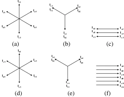
Fig. 2 Sequence components of a six-phase source (a) First-sequence (b) Second-sequence (c) Third -sequence (d) Fourth-sequence (e) Fifth-sequence (f) Sixth- Fifth-sequence component.
The first-(positive) sequence component system consists of six phasors displaced 600 relative to each other whereas the second-sequence component system consists of three phasor displaced 1200 relative to each other, each phasor representing two phases- constituting two three-phase superimposed positive sequences. The third-sequence component system has two phasors displaced 1800 relative to each other, each representing three phases constituting two three-phase zero sequences in opposition whereas the fourth- sequence component system is a sequence in the opposite sense of rotation to that of the second-sequence system. Similarly, the fifth-(negative) sequence component system is a sequence of phasors in the opposite sense of rotation to that of the first-sequence system. The sixth sequence component also known as zero sequence components has all the six phasors placed at zero degree apart to each other. It is to be noted that the instantaneous vector pairs
i
a1,i
a5 andia2,ia6 are complex conjugatepairs whereas
i
a0and ia3are real quantities, which is zero,if mains currents are balanced.
C Derivation of Reference Currents
The aim of the compensator is to make the source current balanced and operates at desired power factor. As said earlier, the amount of the shunt current required to make the source current balanced in presence of unbalanced load, is referred as the reference current. There are six compensating current and therefore six linearly independent simultaneous equation need to be formulated and solved. As known from the symmetrical component theory, a balanced system of current, the zero sequence components will have zero summation value. Accordingly, to provide balanced source currents, the zero sequence components added together must be zero i.e.
0
sb sc sd se sf
sa i i i i i
[image:2.595.52.292.126.265.2]device, wasting completely the capability of the source to supply the reactive power. Therefore, all the practice compensators are expected to partially compensate.
Let
be the desired the power factor angle between1
sa
v
andi
sa1(positive sequence components), then the following equation must hold true.
)
(
)
(
5 4 2 5 4 2 f se d sc sb sa sf se sd sc sb sai
b
i
b
i
i
b
bi
i
v
b
v
b
v
v
b
bv
v
(3)For a balanced operation, all sequence components except positive sequence will be zero. For a balanced circuit, the following holds true.
sd sa
i
i
,i
sb
i
se,i
sc
i
sf (4)Let the instantaneous real power of the load be given by
sf sf se se sc sc sb sb sa
sa
i
v
i
v
i
v
i
v
i
v
=p
lav.
(5)Solving (3), by taking
b
e
j/3 we obtain )( 2
/ A B
(6) where,A
v
sa
b
2v
b
b
4v
c andB
i
sa
b
2i
b
b
4i
c Taking tangent on both sides of (6) and solving together (2) to (6) fori
si(i a,b, f ); all the source currents, in the balanced operation of the power system, can be explicitly defined in terms of the other variables. Phase ‘a’ currenti
sais shown in (7) as an example.
2 lav sc sb sa sa p v v v i
(7)Where,
3
tan
and
=v
2sa
v
2sb
v
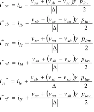
2scIt is to be noted that the calculated source currents are for balanced operation of an unbalanced load. If the compensator is designed in such a way that the unbalance component of the load currents is supplied by the compensator and balanced component from the source, KCL at node point of common coupling (PCC) will give the reference current for compensator (8) to (13)
2 lav sc sb sa laca i v v v p
i (8)
2 lav sa sc sb lbcb i v v v p
i (9)
2
lav sb sa sc lccc
i
v
v
v
p
i
(10)
2 lav sc sb sa ldcd i v v v p
i (11)
2 lav sa sc sb le ce p v v v i i (12)
2 lav sb sa sc lfcf i v v v p
i (13)
For practical realization of the compensator, a current controlled voltage source inverter can be used for the current source with the reference current, derived above, tracking. In next section, an ideal switch and diode based compensator has been proposed for a six-phase load. III. ASIX-PASECOMPENSATIONREALIZATION Current controlled voltage source inverter can do a practical realization of the compensator. Using this principle, an ideal switch based compensator is proposed. Let it be called as a six-phase DSTATCOM as its circuit topology is an extension of a conventional three-phase DSTATCOM. The topological description of the proposed six-phase DSTATCOM, its circuit analysis and methodology of simulation for verification are briefly discussed as follows
A. Topology of Six-Phase DSTATCOM
The topology of the proposed six-phase DSTATCOM has been derived from its three-phase counterpart where an inverter circuit is employed with a self-charged capacitor as DC source and unbalanced load circuit connected at PCC as load to the inverter. The proposed six-phase compensator consists of six arms of a single-phase H- inverter circuits as shown in Fig.3 with split capacitor for providing the neutral point n’ of the compensator.
Rch Lch
Sch1
Sch2 i0
ica icb icc icd
ice icf i2 Vc1 Vc2 n' Chopper
Load ZA
Load ZB
Load ZC
Load ZD
Load ZE
Load ZF
vsa
vsb
vsc
vsd
vse
vs f
il b
il c
il d
il e
il f
is b
is c
is d
is e
is f
N
is a il a
a b c d e f
R L
Sa1 Sb1 Sc1 Sd1 Se1 Sf1
Sa2 Sb2 Sc2 Sd2 Se2 Sf2
i1
To Error Amplifier
Error Amplifier
Vc1+Vc2
Set Reference
PI Controller
To switch Sch1and Sch2 of Chopper
[image:3.595.307.556.354.533.2]n
Fig. 3. Six-phase 7-wire distribution System with DSTATCOM
B. Analysis of six-phase DSTATCOM
To illustrate the working of the converter, phase -a of the six-phase compensator shown in Fig.3 has been analyzed. The equivalent circuit of phase 'a' with switch Sa1 closed is
shown in Fig.4. The current through the switch Sa1 is the
series current ica, which can be determined by applying
KVL for the circuit.
[image:3.595.49.209.584.775.2]a R L n' sa v 1 c V 2 c V 1 a S 2 a S 1
i
2i
ca iThe resulting equation is given by (14) L v L V S V S i L R dt
di c sa
a c a cb
ca 2
1 (14)
Where Sa is switching function defined by (15) and is complement of the switching function Sa.
otherwise on is switch if Sa 0 1 (15)
The sources are assumed to be ideal and the impedance blocks shown in Fig. 1 express loads for each phase. For a physical realization of the converter circuit, the loss occurring in all the elements of the compensator and connecting inductor or transformer must be compensated by exchange of real power from source to DC side capacitor of the DSTATCOM. Therefore the reference currents expressed in (8-13) are replaced by additional loss term (Ploss) in the power. The modified version for compensator current for phase-a is given by (16).
)
(
)
(
* loss lavg sc sb sa laca
P
P
v
v
v
i
i
(16)
B. Mathematical Modeling and Simulation for Six-phase DSTATCOM
Simulations have been carried out for the proposed six-phase DSTATCOM to validate the proposed compensation scheme. The state space equations has been written in terms of the switching functions (Sa,Sb) of the converter and (Su &Sl) of chopper of the DSTATCOM and solved by Runga-kutta method in MATLAB by ode45 function. The state space equations of the six-phase compensator system are given in (17-22).
L v L V S L V S i L R dt
di c sa
a c a ca
ca 1 2 (17)
L v L V S L V S i L R dt
di c sb
b c b cb
cb 1 2 (18)
L v L V S L V S i L R dt
di c sc
c c c cc
cc 1 2 (19)
L v L V S L V S i L R dt
di c sd
d c d cd
cd 1 2 (20)
L v L V S L V S i L R dt
di c se
e c e ce
ce 1 2 (21)
L v L V S L V S i L R dt
di c sf
f c f cf
cf 1 2 (22)
The chopper dynamics has been realized by writing the state space equations for the circuit shown in Fig. 3. Let i1 and i2
be the currents in circuit of the chopper (Fig. 3), then (23) and (24) represents the relation of these in terms of switching function and the converter currents.
cf f ce e cd d cc cb
ca Sb i Sc i S i S i S i
i Sa
i1 * * * * * * (23) cf f ce e cd d cc c cb b ca
a i S i S i S i S i S i
S
i2 * * * * * * (24)
The final expressions (25) - (27) can be obtained by applying the principle of KCL and KVL.
C i S C i S C i S C i S C i S C i S C i S dt V ch u cf f ce e cd d cc c cb b ca a C * * * * * * *
1 (25)
C i S C i S C i S C i S C i S C i S C i S dt V ch l cf f ce e cd d cc c cb b ca a C * * * * * * *
2 (26)
ch c l ch c u ch ch ch L V S L V S L R dt
di 1 2 (27)
The variables used in the expressions (25)-(27) are indicated in the circuit diagrams. The capacitor voltages reduce if not compensated for the losses in the connecting transformer/ inductor, which can be accounted by changing the duty cycle of the chopper. The change in duty of the chopper is based on the change in the capacitor voltage from the set reference voltage. The difference in the capacitor voltage and set voltage (i.e. the error voltage) is put forward to a proportional-integral (PI) controller. The PI controller estimates the Ploss component as stated in (16) and determines the duty cycle of the chopper to maintain the capacitor voltage at a pre specified set reference voltage. The set values are taken approximately 1.3 times the peak AC voltage of the source voltage for compensator to work satisfactorily.
IV. SIMULATIONSTUDIES
The simulation study has been carried out to validate the proposed six-phase DSTACOM for various cases of unbalanced loadings, and phase outages. The results and analyses for each case are discussed in the sections to follow.
A. Compensation of unbalanced Loads
The simulation of the converter and compensator has been carried with the following parameters. The voltages
) , , , , ,
(p a b c d e f
vsp and the impedances
) , , , , ,
(p a b c d e f
Zp all in ohm for the six-phase system are employed as follows.
)
3
/
*
100
(
sin
26
.
325
t
i
v
si
, where i = 0, 1,2, 3, 4, 5 corresponding to phase a, b, c, d, e, f respectively. 25
25 j
Za ,Zb 15 j20,Zc 10 j20,
25 20 j
Zd ,Ze 20 j5,Zf 30j30 (28) The isolation transformer parameters are as follows:
R= 1 and L = 200 mH
.
The control parameters for regulating the capacitor voltage of the chopper are adjusted heuristically and are given in (29).
p
K
= 1K
i= 10 (29)seen from Fig. 5 (b) and Fig. 5(c) that the load currents are highly unbalanced and equal when compensator is not turned on. After 0.02 sec. when the compensator is turned
[image:5.595.306.548.50.161.2]on source currents are perfectly balanced as shown in Fig. 5 (c). In order to compensate the unbalanced load currents, the compensator currents become unbalanced accordingly as shown in Fig. 5(d).
Fig. 5 Variation of source voltages and load current, source and compensator currents for 6-phase 7-wire supply system.
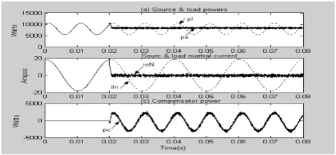
The three instantaneous powers namely source; load and compensator powers are shown in Fig. 6 (a) & (c), while two neutral currents (source & load neutral currents) are plotted in Fig. 6 (b). It can be seen that before compensation, that is, when compensator is switched off,
source power and load power have the same magnitude and are of oscillating nature as shown in Fig. 6 (a). This is due to unbalance in load currents. But after compensation (when compensator is turned on) the source power attains a steady state value as can be seen from Fig. 6 (a) while load power is oscillating Fig. 6(a). Moreover, the source neutral current attains zero value as shown in Fig. 6(b) when the compensator is turned on as it balances the source currents. This also implies that the sum of the instantaneous compensator currents is equal to load neutral current
Fig. 6 Variation of power and neutral current for a 6-phase 7-wire supply system
The variation of cophasors-voltage and currents shows unity power factor operation with compensator as it is evident from Fig.7 It can be seen from (28) that impedances are unbalanced and have all reactive elements except one, but the currents are not only balanced but also operate at unity power factor with compensator
Fig. 7 (a)-(d) (1:7) scaled source voltages (dashed line), source currents (solid line) (e) variation of compensator currents portraying unity power factor operation for a 6-phase 7-wire supply system
[image:5.595.46.287.144.265.2]The D.C. link capacitor maintains the constant voltage through the PI controller. The voltage variation of individual capacitor is shown in Fig. 8. Please note that the capacitor voltage is assumed to be initially charged or pre-charged
Fig 8 Capacitor voltage variation
B. LLooaaddCCoommppeennssaattiioonnffoorrpphhaasseeoouuttaaggeess
The advantages of loads like motor in its capacity to op- rateThe advantage of multiphase loads like motor is in its capability to operate with phase outage. The motor operates with degraded performance and source sees an unbalanced operation and therefore other loads connected to such a source get affected. The proposed compensator has been tested with various combination of phase outages and it has been found that it works satisfactorily even with three phases open (with phase outage (a, b, c )) in a six phase source. The result is shown in Fig. 9 & 12 where the entire source currents are balanced with compensator on.
Fig. 9 Variation of source voltage & various currents for the phase outage (a, b, c) of the load for a 6-phase supply system.
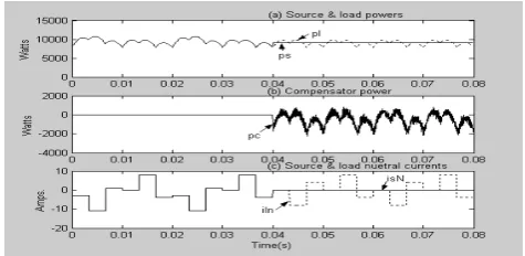
[image:5.595.305.542.291.399.2] [image:5.595.46.291.505.618.2] [image:5.595.307.545.596.702.2]Fig. 10 Variation of powers and neutral currents for phase phase outage (a, b, c) of load for a 6-phase supply system
[image:6.595.46.290.51.167.2]Fig. 11 (a)-(d) (1:7) Scaled source voltages (dash line), source currents (solid line) & (e) variation of compensator currents portraying unity power factor operation for phase outage (a, b, c) of the load for a 6-phase supply system.
Fig 12 Capacitor voltage variation for phase outage (a, b, c) of the load for a 6-phase supply system.
C. Load Compensation for non-linear load
The proposed compensation scheme has also been tested with nonlinear loadings by simulating a rectifier load for each phase drawing a constant d.c. current from each phase. The simulation results are presented in Figs. 13-16. A brief summary of observation is as follows:
0 0.01 0.02 0.06 0.07 0.08 -500
0 500
Vo
lt
s
0 0.01 0.02 0.06 0.07 0.08 -20
0 20
Am
ps
0 0.01 0.02 0.06 0.07 0.08 -20
0 20
Am
p
s
0 0.01 0.02 0.03 0.04 0.05 0.06 0.07 0.08 -20
0 20
Am
p
s
Time(s) (a)Source voltages
(b)Load currents (c)Source currents (d)Compensator currents
Fig. 14 Variation of source voltage & various currents for a 6-phase supply system
Fig. 15 Variation of powers and neutral currents with non linear loading foa 6-phase supply system
Fig. 16 (a)-(d) (1:8) scaled source voltages (solid line), source currents (dash line) (e) variation of compensator currents portraying unity power
factor operation for a 6-phase supply system
V. CONCLUSION
In this paper, the problem of load balancing and power factor correction at the source side for multi-phase load circuits in the event of linear unbalance loading, phase outages and non–linear loadings have been addressed. For the purpose, a multi-phase compensator (6-phase) have been realized as a multi-phase DSTACOM extending the approach developed for three phase system in the literature. The dynamic behavior of the compensator is also simulated during the load compensation process. An elaborate study has also been made on source voltages, load currents, source currents, and compensator currents during non-compensating and non-compensating period. The capacitor voltage variations and the variation of the load and source powers are also analyzed. The variation of the compensator power at the time of its rise has been explained. The analysis has confirmed unity power factor operation of the source in all cases as evidenced by the voltage and current waveforms.
[image:6.595.47.293.200.306.2] [image:6.595.314.551.204.320.2] [image:6.595.57.291.588.709.2]REFERENCES
[1] E. Levi, R. Bojoi, F. Profumo, H. A. Toliyat, S Williamson,"Multi- phase induction motor drives-a technology status review”, Electr. Power Applications, IET, Vol.1, Issue 4, 2007
[2] D. Yazdani, A. Khajehoddin, G. Joos, “Full utilization of inverter of split phase derives by mean of a dual three phase space vector', IEEE Trans. on
Industrial Electronics, Vol. 56, No. 1, 2009
[3] N. Gule. & M.J. Kamper."Multiphase cage rotor induction machines derive with direct implementation of brush dc operation" IEEE Int. Conf. on Electric Machine and Derive, 2011
[4] H. Akagi,Y. Kanazawa, K. Fugita and A. Nabe, "Generalized theory of instantaneous reactive power and its application," Electrical Engg.
in Japan, Vol. 103, No.4, 1983
[5] H. Akagi, Y. Kanazawa and A. Nabe, "Instantaneous reactive power compensators comparing switching devices without energy storage components", Trans. on Ind.App., vol.1A-20,No.3,1984.
[6] H, Akagi, A. Nabe and S. Atosh, "Control strategy of active power filters using multi voltage-source PWM converter”, Trans. on Ind.App., vol.1A-22 , No.3,1986
[7] M. Z. Elsadek, "Balancing of unbalanced loads using static var copensator," Electr. .Powr .Syst. Res., Vol. 12, 1987.
[8] H. Watanabe, R.M. Stephan and M. Aredes, "New concepts of instantaneous active and reactive powers in electrical systems with generic loads," IEEE Trans. On power Delivery, Vol. 8, No.2, 1993 [9] A. Kern and G. Schroder, "A novel approach to power factor control and
balancing problems” Proc., IECON, 1994
[10] P. Verdelho, and G.D. Marques, "An active power filter and unbalanced current compensator," IEEE Trans. On Industrial Electronics, Vol. 44, No. 3,1997
[11] F. Z. Peng, G.W. Ott, Jr., and D.J. Adams, "Harmonic and reactive power compensation based on the generalized instantaneous reactive power theory for three-phase four-wire systems," IEEE Trans. on Power
Electroics, Vol. 13, No. 6, 1998.
[12] A.Ghosh, A.Joshi, A new approach to load balancing and power factor correction in power distribution system,” IEEE Trans.on power deliveryvol. 15, No.1, 2000.