Antiscarp initiation and evolution
A thesis submitted in partial fulfilment of the requirements for the degree of
Doctor of Philosophy in Engineering Geology
at the
University of Canterbury by
Verne Harlan Pere
ii
Abstract
Antiscarps are defined here as any uphill facing scarp that may be observed on slopes, regardless of size or scale. They are not present on all slopes, but where they have been observed, they typically occur sub-parallel to the valley axis near the ridge crests in mountainous regions. Antiscarps are generally, but not exclusively, found in glaciated regions, where loading and unloading of the rock mass has effected changes to the in situ stress fields through cycles of compression and elastoplastic rebound and has also removed large volumes of material by the formation of cirques. Non-glacial antiscarps are commonly associated with tectonic activity.
An extensive review of current literature has been used to assist in the identification of key parameters associated with antiscarps and to provide a basis for clearly defining the
terminology used to address antiscarp related processes and features. All of the reviewed material has been collated into a chart where the factors that have been extracted from the articles are grouped and compared. The chart has been instrumental in selecting the
nomenclature to be used when addressing different types of antiscarp and also in constraining the extent to which the term can be reasonably used.
A flowchart has been developed to assist in the identification of the primary antiscarp forming process. The flowchart was successfully used to identify the primary processes associated with antiscarps observed in field studies in both the South Island of New Zealand and in the Scottish Highlands.
iii
Table of Contents
Abstract ... ii
Table of Contents ... iii
List of Figures ... ix
List of Tables ... xviii
Appendices ... ix
Acknowledgements ... xix
1 Antiscarp initiation and evolution ... 1
1.1 Motivation ... 1
1.2 Objectives ... 2
1.3 Methodology ... 2
1.3.1 Literature review ... 2
1.3.2 Compilation of an antiscarp processes flowchart ... 3
1.3.3 Field studies ... 3
1.3.4 Modelling ... 4
1.4 Thesis organisation ... 5
2 Antiscarp terminology, properties and geological setting ... 6
2.1 Review table ... 6
2.1.1 Factor selection ... 7
2.1.2 Data limitations ... 7
2.1.3 Data presentation ... 8
2.2 Currently used terminology ... 8
2.2.1 Morphology based terminology ... 8
2.2.1.1 Antiscarp ... 8
2.2.1.2 Oblique antiscarps ... 10
2.2.1.3 Lineations ... 10
2.2.1.4 Tension cracks ... 12
2.2.1.5 Release joints ... 14
iv
2.2.1.7 Doppelgrat ... 15
2.2.1.8 Ridge rent ... 20
2.2.1.9 Bulging ... 20
2.2.2 Process-based terminology ... 22
2.2.2.1 Gravity faulting... 22
2.2.2.2 Ridge splitting... 22
2.2.2.3 Sackung ... 22
2.2.2.4 Mass rock creep ... 25
2.2.2.5 Toppling... 25
2.2.2.6 Wedging... 29
2.2.2.7 Spreading ... 29
2.2.2.8 Deep-seated gravitational slope deformation ... 30
2.2.2.9 Unloading ... 30
2.3 Antiscarp properties ... 31
2.3.1 Geometric attributes ... 31
2.3.2 Aspect to the slope ... 31
2.3.3 Frequency and distribution ... 33
2.3.4 Timing constraints ... 34
2.3.5 Deformation rates ... 35
2.3.6 Longevity and preservation ... 36
2.4 Rock mass properties ... 37
2.4.1 Rock strength ... 37
2.4.2 Discontinuities ... 38
2.4.2.1 Joints ... 39
2.4.2.2 Foliation ... 40
2.4.2.3 Bedding ... 40
2.4.2.4 Discontinuity strength... 40
v
2.4.4 Heterogeneous massifs ... 42
2.4.5 Homogeneous massifs ... 42
2.5 Geological setting ... 42
2.5.1 Glaciation ... 43
2.5.1.1 Glacial loading/unloading ... 43
2.5.1.2 Post-glacial debuttressing ... 44
2.5.1.3 Glacial oversteepening ... 44
2.5.1.4 Water table ... 44
2.5.2 Fluvial incision ... 45
2.5.3 Tectonic setting ... 45
2.5.4 Seismicity ... 46
2.5.5 Massif symmetry ... 47
2.6 Applications of antiscarp terminology and properties ... 47
3 Antiscarp classification ... 48
3.1 Antiscarp definitions ... 49
3.1.1 Motivation ... 49
3.1.2 Scope and presentation of the definitions ... 49
3.1.3 Thesis glossary ... 50
3.2 Antiscarp classification ... 51
3.2.1 Limitations of the classification scheme ... 52
3.2.2 Antiscarp classification scheme ... 52
3.3 Applications for the classification scheme ... 54
4 Field studies ... 55
4.1 Kelly Range case study ... 55
4.1.1 Geological setting ... 55
4.1.1.1 Lithology ... 56
4.1.1.2 Structure... 59
4.1.1.3 Climate... 62
vi
4.1.1.5 Tectonic history ... 64
4.1.2 Antiscarps ... 65
4.1.2.1 Classification ... 72
4.2 Beinn Fhada... 72
4.2.1 Geological setting ... 72
4.2.1.1 Lithology and structure ... 73
4.2.1.2 Glacial history... 74
4.2.1.3 Tectonic history ... 74
4.2.2 Antiscarps ... 75
4.2.2.1 Classification ... 83
4.3 Ben Each ... 84
4.3.1 Geological setting ... 84
4.3.1.1 Lithology ... 84
4.3.1.2 Structure... 84
4.3.1.3 Glacial history... 84
4.3.1.4 Tectonic history ... 85
4.3.2 Antiscarps ... 85
4.3.2.1 Classification ... 90
4.4 Lewis Tops ... 91
4.4.1 Geological setting ... 91
4.4.1.1 Lithology ... 91
4.4.1.2 Structure... 91
4.4.1.3 Glacial history... 91
4.4.1.4 Tectonic history ... 92
4.4.2 Antiscarps ... 92
4.4.2.1 Classification ... 96
4.5 Stag Hill... 97
vii
4.5.1.1 Lithology ... 97
4.5.1.2 Structure... 97
4.5.1.3 Glacial history... 97
4.5.1.4 Tectonic history ... 98
4.5.2 Antiscarps ... 98
4.5.2.1 Classification ... 99
4.6 Comments on the field studies ... 100
5 Antiscarp modelling ... 102
5.1 Physical modelling using base friction models ... 102
5.1.1 Base friction table set-up ... 103
5.1.2 Model construction ... 104
5.1.3 Base friction tests and test properties ... 104
5.1.4 Hexagons ... 105
5.1.5 Circles – 30º models ... 108
5.1.5.1 Confined base ... 108
5.1.5.2 Semi-confined base ... 109
5.1.5.3 Unconfined base ... 112
5.1.6 Circles – 60º models ... 112
5.1.6.1 Confined base ... 112
5.1.6.2 Semi-confined base ... 112
5.1.6.3 Unconfined base ... 115
5.1.7 Diamonds – 30° models ... 117
5.1.8 Diamonds – 60° models ... 117
5.2 Base friction modelling summary ... 119
5.3 Numerical modelling ... 120
5.4 Plaxis ... 121
5.4.1 Grid construction ... 121
5.4.2 Material values ... 122
viii
5.4.4 Plaxis volume removal models ... 123
5.5 FLAC 2D ... 126
5.5.1 Grid construction ... 126
5.5.2 Material values ... 126
5.5.3 FLAC Gravity models ... 126
5.6 Numerical modelling summary ... 129
5.7 Modelling conclusions ... 129
6 Discussion ... 130
6.1 Antiscarp features and processes... 130
6.1.1 Discontinuities ... 130
6.1.2 Post-glacial rebound ... 130
6.1.3 Seismicity ... 131
6.1.4 Ridge rents ... 131
6.1.5 Cirques and large scale volume removal ... 132
6.1.6 Rock mass homogeneity ... 132
6.2 Movement rates and exposure time ... 132
6.3 Antiscarp evolution ... 133
6.3.1 Kelly Range example ... 133
6.3.2 Beinn Fhada example ... 136
6.4 Antiscarp classification ... 138
6.5 Field studies... 138
6.6 The role of gravity ... 138
6.7 Water ... 139
6.8 Future work ... 139
6.8.1 Trenching of tarns ... 139
6.8.2 Numerical modelling ... 139
6.8.3 Physical modelling ... 140
7 Summary and conclusions ... 141
7.1 Study objectives ... 141
ix
7.3 Field studies... 142
7.4 Modelling ... 143
7.5 Key outcomes ... 144
8 References and bibliography... 145
Appendices
Appendix A: Base friction modelling ... 162A.1 Steel M4 hexagonal nut 10mm shift confined base. 30º + vertical on the left with 60º + horizontal on the right. ... 163
A.2 Round 5c coins 50mm shift confined 30º + vert. ... 167
A.3 Round 5c coins 10mm shift confined 30º + vert. ... 168
A.4 Round 5c coins 10mm shift semi-confined 30º + vert. ... 171
A.5 Round 5c coins 10mm shift unconfined 30º + vert. ... 173
A.6 Round 5c coins 10mm shift confined 60º + horz. ... 175
A.7 Round 5c coins 10mm shift semi-confined 60º + horz. ... 176
A.8 Round 5c coins 10mm shift unconfined 60º + horz. ... 178
A.9 Pattern blocks 10mm shift confined 60º ... 180
A.10 Pattern blocks 10mm shift confined 30º ... 181
List of Figures
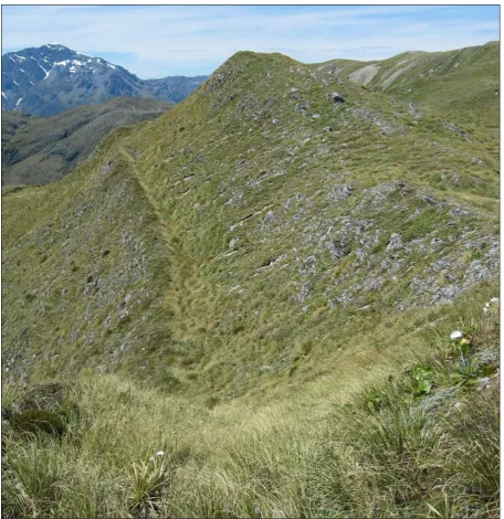
Figure 2.1: Antiscarps on the Kelly Range, Otira, New Zealand, are highlighted by white arrows in Figure 2.1A. Multiple antiscarps on Beinn Fhada (Ben Attow), Kintail region, Scotland, in Figure 2.1B show a wide variance in the degree of displacement. ... 9x
large white arrow in Figure 2.2A shows the direction of view for Figure 2.2B. The person in the central part of the photograph gives a scale of around 1.8m. ... 11
Figure 2.3: Antiscarp features are accentuated by snow on Kelly Hill, Otira, New Zealand, and form lineations, running across the picture, when viewed from above (Image sourced from Google Earth). ... 12
Figure 2.4: A tension crack on the Kelly Range (approximately 500m south of Figure 2.1A) is highlighted by the red arrows with the yellow arrows and lines showing the amount of dilation expressed at the surface. The person in the picture stands to the west of the tension crack and provides a scale of 2m. ... 13
Figure 2.5: Release joints as presented by Slivovský (1970) showing the release of sheets of rock following unloading of the rock mass in A) slopes and B) valley floors. ... 14
Figure 2.6: Formation of doppelgrate through bedding or joint controlled translational failures (Jahn 1964)... 16
Figure 2.7: Bulging in the toe of a slope can form under both tensional and compressional conditions. Lateral extension within Figure 2.7A is considered to form crestal graben along with suites of antiscarps, clustered on the upper slope and in the bulging lower slope. In Figure 2.7B antiscarps are associated with extension in the upper slope while the lower slope bulging is related to compression. ... 17
Figure 2.8: Exposed face to the northeast of the Kelly Saddle, Otira, New Zealand, looking down the axis of the ridge. The models proposed by Beck (1968) (refer Figure 2.9) are indicative of what can be observed at this outcrop. Intersecting joint sets define the margins for graben style collapse with two joint sets identified by the red and yellow arrows. ... 18
Figure 2.9: Alternative mechanisms for the formation of antiscarps related to gravity faulting (Beck 1968). Topographic lowering is associated with graben style collapse in response to lateral movement within the massif. All models infer lateral movement in the lower sections of the massif, in some instances below the valley infill, whether through the extrusion of crushed rock or by displacing material in the valley. Oversteepening as a result of lateral movement is only seen to occur in Figure 2.9B, with both of the other scenarios effectively shallowing the slope angle relative to its pre-deformation position. ... 19
Figure 2.10: Lateral movement of the granogabbro is driven by slow plastic deformation in the lower strength shale via the process of ridge splitting to form antiscarps and a doppelgrat. Surficial deposits on the lower flanks of the slope may give the appearance of bulging. ... 21
xi
degradation above the crack. The displaced lower section is consequently undergoing tilting out of the slope, or more correctly toppling, during this process. When placed in the broader context of the massif, as seen in part B, Jahn argues for accommodation of slope debris within the tension cracks which highlights the appearance of antiscarps and doppelgrat in the slope profile (Jahn 1964). ... 23
Figure 2.12: Velocity profiles developed by Zischinsky (1966) reflect observed strain within a massif under conditions of plastic deformation, for the sackung, and after a throughgoing failure surface has developed, in the case of the gleitung... 24
Figure 2.13: Rates at which creep may operate to give the same total displacement. A) constant strain rate with the dotted line showing the relationship with multiple small displacements; B) single event displacement; C) multiple displacement events; and D)
multiple displacement events with an accompanying constant strain rate. ... 26
Figure 2.14: Modes of toppling (Figures A, C, and D from Turner and Schuster 1996) ... 27
Figure 2.15: A slide topple where blocks of brittle material are rotated during down slope transportation driven by plastic deformation in the underlying rock (Kamenov et al. 1977). . 28
Figure 2.16: Wedging failures as proposed by Brown (1997). ... 29
Figure 2.17: An idealised massif showing the measurement parameters for antiscarps. ... 32
Figure 2.18: Distribution of values for antiscarp measurements determined from Chart 1. ... 32
Figure 2.19: A single large antiscarp referred, to as a sackung in this picture, cuts across the massif in Gillett Pass, Alaska, and is considered to have been reactivated during the M7.9 Denali earthquake in 2002 (from McCalpin, http://www.geohaz.com/GravSpread4.htm) ... 34
Figure 2.20: UCS of phyllites under varying angles of the schistosity to the applied load (modified from Jaegar 1972). ... 41
Figure 2.21: Response of a slope to rapid drawdown (Turner and Schuster 1996) ... 46
Figure 2.22: Stress distributions in a variety of asymmetric landforms (Kinakin and Stead 2005) ... 47
Figure 3.1: Flow chart classification scheme for assessing antiscarps from initial observations through to a probable mechanism. ... 53
xii
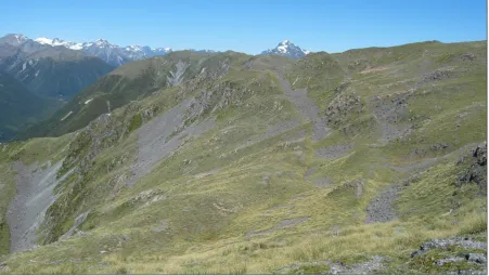
Figure 4.2: Google Earth image of Kelly Range. The snow cover helps to contrast the
antiscarp features (refer to Figure 2.3 for an image centred on Kelly Hill). ... 57
Figure 4.3: Sheared and fractured weathered Torlesse quartzofeldspathic sandstone. Bedding is dipping moderately to the right in this photograph (bedding plane denoted by the arrows). ... 57
Figure 4.4: Poorly developed foliation within weathered Torlesse sandstone. ... 58
Figure 4.5: Till deposits on the ridge at the south western end of Kelly Range. The person in the photograph provides a scale of 2m. Glacial overtopping of the ridge is considered to have created the smooth nature of the slope above the incised till. The till extends to the break in slope to where it becomes the Torlesse bedrock. ... 58
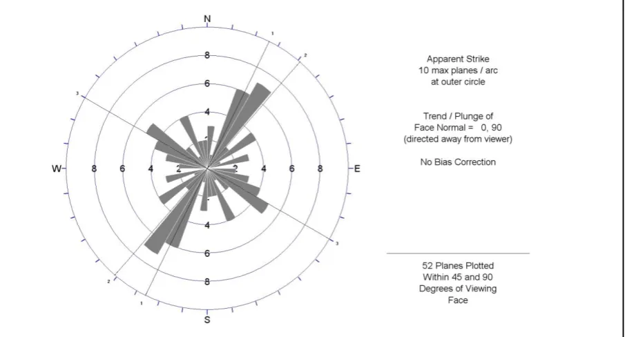
Figure 4.6: Rose diagram of the apparent strike calculated in DIPS using defect measurements from the Kelly Range. The preferred strike orientation is in a NE – SW direction with a second set of structures in the NW – SE. Three defect sets are identified in the DIPS data and the apparent strikes for each of these is represented by line across the stereonet with a corresponding set number on the perimeter. ... 59
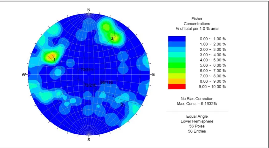
Figure 4.7: Initial pass of the Kelly Range discontinuity data presented as a stereonet contour plot. ... 60
Figure 4.8: Search windows as used around data clusters to calculate representative poles, indicated by the crosses, for the Main Kelly Range discontinuity sets. ... 60
Figure 4.9: The three primary discontinuity sets. Poles 1 and 2 correspond to the structures associated with the SE dipping and NW dipping antiscarp sets respectively. Pole 3 is of a similar orientation to the exposed face just to the southwest of Kelly Hill (Figure 4.10). ... 61
Figure 4.10: View to the north east from the top of the slope in Figure 4.12 on to the face below Kelly Hill. Structure Set 1 has an apparent southeast dip (red arrows) and Set 2 dips toward the northwest (yellow arrows). Structure set 3 parallels the slope face. Sets 1 and 2 can be easily tracked up the slope coming toward the front of the picture. Figure 4.12 shows the reverse view. ... 61
Figure 4.11: This photograph is taken from Kelly Saddle, beneath the face shown in Figure 4.10, and allows a view up structure Set 3 which roughly parallel the slope. The tarn is a common feature associated with many antiscarps on the Kelly Range and at this locality is within Set 1. ... 62
xiii
evident on the facing slope is due to the SW trend and plunge of the intersection between structure Set 1 (red arrows) and Set 2 (yellow arrows) (refer section 4.1.1.2) going into the slope. ... 63
Figure 4.13: View to the southwest across Kelly Stream from the top of the slope in Figure 4.12. A glacial trim line is clearly demarcated, not only on the opposing range but also on the southeast facing slope in the foreground, by a distinct steepening of the slope and also a vegetation change. Hanging valleys and cirques are also evident on the range in the background. Fluvial incision is an ongoing process through this area contributing to
oversteepening of the valleys. ... 63
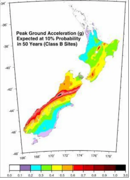
Figure 4.14: Peak ground accelerations (g) expected at 10% probability in 50 years for intermediate soil sites (from Stirling et al. 2002). ... 64
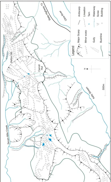
Figure 4.15: Geomorphological map of the Kelly Range. ... 66
Figure 4.16: An antiscarp at the southern end of Kelly Range related to structure Set 1. Approximately 2m of net separation along the scarp has occurred at this locality. View is to the north. ... 68
Figure 4.17: View south along structure Set 2 antiscarps on the slope to the east of Kelly Hill. Approximately 5m of separation is observed at this locality. Of note is the amount of infill, or lack of, within these antiscarps. Where there is a source rock for the production of scree the antiscarps act as a highly effective natural bund. ... 69
Figure 4.18: View to the south from the north end of the Kelly Range with Kelly Hill denoted by the communications aerial upon it. The antiscarps to the left of the peak are from Set 1 and have about 6m to 7m of displacement. There is a noticeable lack of scree or rock infill in the antiscarps on this side of the ridge (western slope). ... 69
Figure 4.19: View north towards Kelly Saddle with tarns formed within Set 1 structures. .... 70
Figure 4.20: Further to the south of Figure 4.19 with another tarn within western slope Set 1 antiscarps... 70
Figure 4.21: Another smaller tarn within western slope Set 1 antiscarps ... 71
Figure 4.22: View to the south with the tarn formed in Set 1 antiscarps. The antiscarp is to the right of the picture and has about 10m of displacement. ... 71
xiv
Figure 4.24: Geological map of Scotland. The Moine Thrust is denoted by the two red arrows (map from
http://www.scottishgeology.com/geology/geology_of_scotland_map/scotland.html). ... 73
Figure 4.25: Psammite from Beinn Fhada with typical gneissic texture. ... 74
Figure 4.26: A precariously balanced rock on the crest of an antiscarp. The locality of this rock is suggestive of a very low probability of shaking being experienced within this region. It is inferred that this rock would most likely have been dislodged by relatively low levels of seismicity. ... 75
Figure 4.27: Geomorphological plan of Beinn Fhada. ... 77
Figure 4.28: View to the northwest along the southwest slope of Beinn Fhada. Multiple linear antiscarps are evident running along the strike of the slope. ... 78
Figure 4.29: View to the southeast along the southwest slope. The even amount of
displacement of the antiscarp along its length, even as it crosses undulations and interfluves across the slope, is well represented at this locality. This feature is one of the key arguments against the antiscarps here being a product of glacial action such as a trim line or selective plucking of material from within the antiscarp. ... 79
Figure 4.30: Increased degradation of the antiscarps in the lower section of the slope is attributed to inundation by surface processes, initially lower antiscarp heights, and trampling by livestock. ... 79
Figure 4.31: Some of the larger antiscarps observed on the slope with heights of around 10m. This is a different perspective of the antiscarps in Figure 4.29. ... 80
Figure 4.32: View to the northwest along another of the larger 10m high antiscarps. Note the lack of rockfall material or slope debris within the antiscarp; this is typical of the antiscarps within the upper section of the slope. Infill in the lower slope antiscarps tends to be finer grained material rather than rocks. ... 80
Figure 4.33: A view downslope into the antiscarp in Figure 4.32. Sheep on the right of the antiscarp for scale. ... 81
Figure 4.34: View to the northwest along the southwest slope where it joins with the shallow ridgeline. ... 81
xv
Figure 4.36: Further up the slope again looking along the ridge to the northwest. Note the three cirques on the northeast side of the ridge (right side of the photo) that have eroded all the way through to the ridgeline. ... 82
Figure 4.37: View northwest along the ridge looking into bedrock exposed within one of the cirques on the northeast slope. The foliation is steeply dipping to the northeast and is strongly aligned with the orientation of the antiscarps. ... 83
Figure 4.38: Another photo looking into a different cirque on the northeast slope. Again the foliation is dipping to the northeast and is sympathetic to the orientation of the antiscarp structures. ... 83
Figure 4.39: This photo is taken from above the face in Figure 4.40. There is an obvious tension crack behind the face that is dilated, with a second tension crack also apparent just below the summit. ... 85
Figure 4.40: The exposed face in this photograph is on the ridgeline near the summit of Ben Each. The structure exposed in this face is bedding and the orientations are coincidental to the same structures associated with the A2 antiscarp sets. ... 86
Figure 4.41: Another outcrop showing the discontinuity set that aligns with the A2 antiscarp set. ... 86
Figure 4.42: View towards the north with A2 antiscarps cutting across from the top right to the bottom left corner. Antiscarp heights are approximately 2m here. ... 87
Figure 4.43: Looking towards the north along remnants of A1 set antiscarps. Two A2
antiscarps cut down across the picture from the top right corner towards the bottom left. This picture is downslope from Figure 4.42. Antiscarp heights are less than 1m here and appear quite muted... 87
Figure 4.44: Looking down the south plunging A2 set into the intersection with the A1 set. Both sets appear to offset each other which is common for the intersections observed on this slope. The variable antiscarp heights of the intersections suggest movement on the different sets may have been contemporaneous or that movement varies between the two sets. Typical heights in this area ranged from 1m to 8m. ... 88
Figure 4.45: 12m high oblique antiscarp associated with the A2 set. Person in centre of the photo is approximately 1.8m tall for scale. ... 88
xvi
on the slope. The heather on the slope (darker brown pink flowered shrub) sits within the lineation up the centre of the picture which is a poorly developed, or infilled, antiscarp. ... 89
Figure 4.47: Another of the springs along the same alignment as the one identified in Figure 4.46... 90
Figure 4.48: Intersection between an oblique antiscarp with a ridge parallel antiscarp. The ridge parallel antiscarp extends along the slope in both directions while the oblique antiscarp terminates at this intersection. Both people in this photo are approximately 1.8m tall. The ridge parallel antiscarp is approximately 0.5 m at this locality with the oblique antiscarp ranging between 1m and 1.5 m. (Reproduced from Figure 2.2B). ... 93
Figure 4.49: View to the west of the northern slope. Of note is the development of scree slopes. There are remnants of antiscarps evident in the outcrop adjacent to the scree slope. . 93
Figure 4.50: View to the east along the northern slope. ... 94
Figure 4.51: View to the west along the southern slope. Multiple 1.5 -5m high ridge parallel antiscarps are obvious extending from the lower left of the photograph and extending right along the slope towards Lucretia in the centre background. Several oblique sets are also present with the tarn in the centre lower section of the photo formed against one that extends from the lower right corner up towards the left. Several other oblique antiscarps are also apparent along the slope following the same orientation... 95
Figure 4.52: Tarn within ridge parallel antiscarp set. The slope has a chopped up appearance with the interaction between the parallel and oblique sets. Scarp heights on both sets range between 1 to 5m. ... 95
Figure 4.53: Large tarn within a ridge parallel antiscarp. ... 96
Figure 4.54: Series of tarns within an oblique antiscarp this locality is approximately 250m to the northeast of the same oblique antiscarp in Figure 4.51... 96
Figure 4.55: View to the southwest from Cass Saddle towards Stag Hill. ... 98
Figure 5.1: Setup for the base friction table modelling. ... 103
Figure 5.2: The primary discontinuity angles for different shaped elements depend on the relationship of how the elements are stacked relative to the model. The diagram here depicts how a 90 ° rotation of either circular or hexagonal stacked elements result in either a 30° or 60° primary discontinuity angle. For the hexagonal elements there is also a vertical or
xvii
Figure 5.3: Hexagonal base friction models. Both models have a 60° lower slope section with
an upper slope of 30°. ... 107
Figure 5.4: 30° circular element model with secondary vertical discontinuity set. The red blocks in this model are attached to the sliding frame and prevent the base from spreading. ... 108
Figure 5.5: Stages of development in the confined 30º circle model ... 110
Figure 5.6: Initial semi-confined 30º circle model with the deformed model after 150mm of movement. The shallow block topples are evident down the slopes with a wide diamond shaped horst formed in the upper section of the model and a 30º pyramid formed at the base once the elements were no longer able to move laterally along the base. ... 111
Figure 5.7: Unconfined 30º circle model with the initial condition and after a 200mm shift 113 Figure 5.8: Circular element model with confined base and incorporated 60° and vertical discontinuity sets. ... 114
Figure 5.9: Semi-confined 60º circle model ... 114
Figure 5.10: Unconfined 60º circle model after 40mm of sliding. ... 115
Figure 5.11: Unconfined 60º circle model after 80mm of sliding. ... 116
Figure 5.12: Unconfined 60º circle model after 120mm of sliding. ... 116
Figure 5.13: 30° diamond pattern blocks ... 117
Figure 5.14: 60° diamond model. ... 118
Figure 5.15: 60° diamond model after 20mm of sliding. ... 118
Figure 5.16: 60° diamond model after 120mm of sliding. ... 119
Figure 5.17: Plaxis cross-section developed using version 6.1. The dotted lines represent the polygon boundaries and have been assigned low shear strength values to simulate discontinuities within the model. Where the dotted lines extend beyond the model is an artefact of the model and reflects null zones associated with the construction of the original polygons. ... 122
xviii
Figure 5.19: Deformed mesh output from Plaxis where the model has been constructed to
assess the response of the massif to the removal of a large volume of material. ... 125
Figure 5.20: Displacement contours are shaded within the original mesh without any deformation applied to the mesh itself. Displacement decreases downslope with the majority of the movement occurring adjacent to the ridge... 125
Figure 5.21: Meshed FLAC model with the interfaces used to simulate discontinuities outlined in red. ... 127
Figure 5.22: Displacement vectors indicative of a toppling style of slope deformation. ... 128
Figure 6.1: Schematic of antiscarp evolution from the Kelly Range. ... 134
Figure 6.2: Evolution of antiscarps at Beinn Fhada. ... 137
List of Tables
Table 2.1: Some typical strength values for rocks (Hoek 2000). ... 38Table 5.1: Typical Plaxis model input values ... 123
xix
Acknowledgements
I would firstly like to thank my family for their perseverance and constant encouragement as I undertook this course of study, especially my partner Eva. Thanks for sticking by me through thick and thin, I have really appreciated all your awhi and aroha.
Thanks to my Supervisors Tim Davies and Jarg Pettinga for their input and for encouraging me through to the end. Cheers to Dave Bell for his fine conversation, assistance on some of the sticky bits, and general all round encouragement. Thanks also to all the other staff within the University of Canterbury Geology Department for all their input over the past few years.
Thanks to Otago University for generously allowing me access to some of their software and computing facilities, and to Phaedra Upton for her guidance with FLAC 2D.
I would also like to acknowledge the support and funding provided for this Doctorate by the Foundation for Research Science and Technology in the form of the Tuapapa Putaiao Maori Fellowship (Contract UOCX0309) and Ngā Pae O Te Māramatanga for the Doctoral stipend. Thanks also to the University of Canterbury for Te tohu whai hiranga - The Maori
meritorious award and also to the Mason trust for support with fieldwork.
Thank you very much to David Jarman for his assistance in pointing me in the right direction in Scotland and for introducing me to haggis, your support was invaluable. Cheers to Rob Langridge for bringing the Lewis Tops to my attention and for spending the day with me up there.
Thanks to Mai ki Otautahi for all the good times and for all the awhi that was provided within our group. Tu meke!
Thanks also to the doctors, physiotherapists, and other health professionals who helped me through the mid thesis broken back and also to the University of Canterbury for allowing me an extension. Sometimes you don‟t know what you have got until its gone.
1
1 Antiscarp initiation and evolution
1.1 Motivation
Antiscarp is an umbrella term for any uphill facing scarp. Antiscarps are a feature within many mountainous areas and appear as linear features on slopes. There are many different ideas on how antiscarps may form and many proposed processes associated with these ideas.
The majority of antiscarps are features that have endured in the landscape for thousands of years and generally little is known about the exact timing of their formation. The lack of timing constraints adds further complication when trying to understand antiscarps as there is also no control on the rate of formation, which can be anywhere on a scale from creep to episodic movement through to a single event displacement. Some studies have been able to determine rates of movement that are akin to creep but it appears that this is only related to processes that by their nature deform a massif at slow rates. The concept of different antiscarp forming processes having subtly different attributes is an important distinction to make because it assists in being able to identify what the key process may be.
Antiscarps are not a case of singularity, which is where one particular process can be considered as the causal mechanism, but are considered to form under different conditions and therefore driven by different processes. Throughout published literature antiscarps are referred to by a plethora of different terms which are often aligned to different processes. Many of the terms currently in use are increasingly being used to represent more than was originally intended and run the risk of losing their explanatory power. Tighter constraints on the definitions and use of antiscarp-related nomenclature will assist in clearer communication between practitioners when presenting antiscarp related material.
Some antiscarps are related to seismic events. Determining the role of seismicity in antiscarp formation and evolution will assist in understanding how antiscarps may be used as a
2
The role of gravity is important because it is a component of many of the processes that are associated with antiscarp formation. Assessing the role of gravity will help to understand some of the base conditions required for antiscarps to form.
1.2 Objectives
There are two main objectives that this research project aims to achieve.
The first is to provide a systematic approach to identifying and communicating antiscarp features and the related processes. As the body of knowledge surrounding antiscarps continues to grow so must the way in which we communicate this knowledge. Clear and concise definitions are provided for antiscarp-related nomenclature to facilitate better communication and a flowchart is constructed to assist in the identification of primary antiscarp process.
The second objective is to assess the role of gravity in antiscarp formation. In particular there will be a focus on establishing whether antiscarp formation can occur solely under gravity or whether there is a need to have a secondary trigger or process to initiate formation.
1.3 Methodology
Several different avenues of study were undertaken to contribute to achieving the objectives outlined in the previous section and involved an in-depth review of available antiscarp literature, field observations, and modelling of antiscarps.
1.3.1 Literature review
Numerous journal articles and books were reviewed with a focus on extracting information factors that are essential to antiscarp occurrences and processes. These factors were then collated within a chart so that the information could then be interrogated to try and identify and significant trends.
3
Terminology that was identified in the reviewed literature was sorted into expressions that represented aspects of antiscarp morphology and those that related to antiscarp formational processes. Clear definitions for the identified terms and how they relate to antiscarps have been provided. These definitions are integral to the production of an antiscarp formative process flowchart and are also used throughout this thesis.
The key term defined within this thesis is antiscarp, which is thought to be a contraction of antislope scarps although its etymology is uncertain. Antiscarp is a morphological term used to describe any uphill-facing scarp on a slope and its use has no dependence on the process by which it may have formed. A morphological approach to addressing uphill facing scarps is considered necessary as the primary approach because it does not appeal to any process and therefore does not infer any particular process, which is the role of the process based
terminology.
1.3.2 Compilation of an antiscarp processes flowchart
The approach of using morphological properties to determine a process is akin to the use of antiscarp as the umbrella term for all uphill facing scarps, in that process-based terms cannot be used to establish the most likely process without there being confusion. The antiscarp-related information that has been teased out as part of the literature review is presented as a glossary in Chapter 3 to support the production of a system for assessing the most likely process for any observed antiscarp.
A flow chart has been compiled that can be used to input morphological antiscarp properties while following a series of prompts to identify the probable antiscarp formative process, and uses the definitions as presented in the glossary.
1.3.3 Field studies
Five areas were investigated or visited to gain insights and observations on antiscarps in the field. The sites were selected based on the types of antiscarp features that have been observed in the past and also on the likelihood that these localities would provide some insights that could be applied to physical and numerical models.
4
The Kelly Range was chosen because of the work presented by Beck (1968) on gravity faulting as a means of topographic adjustment. The discontinuity sets that are exposed above the Kelly saddle allow a view of a natural cross section through the upper section of a massif with antiscarps. The proximity of the massif to known active faults provided an opportunity to compare these antiscarp structures with others that have formed within a seismically quiet area.
Beinn Fhada has been studied by several authors (Holmes and Jarvis 1985; Holmes and Jarvis 1986; Whiteside 1986; Fenton and Ringrose 1992; Fenton 1992a; Jarman and Ballantyne 2002; Jarman 2003a; Jarman 2003c; Jarman 2006) and has extensive antiscarp development on the southern slope with cirque development on the northern slope. Like the Kelly Range there has been extensive glacial activity in the past with the last glacial maximum appearing to coincide with the onset of antiscarp formation. A key difference between Beinn Fhada and the Kelly Range is the level of seismicity, with Scotland not being exposed to either the same magnitude or frequency of seismic events, thus providing a good basis for comparison.
The other locations visited included the Lewis Tops and Stag Hill in the South Island of New Zealand, and Ben Each in the Trossachs region of Scotland. These trips involved a day of field work where the focus was more on observing the features in the field in order to better understand the subtle differences and similarities across different localities.
Key information taken from the field localities was the physical appearance and geometry of the antiscarps, spatial distribution, other associated slope features, field estimated rock mass properties, and a general overview of the geological setting of the with a focus on identifying glacial and/or tectonic features.
1.3.4 Modelling
Both physical and numerical models were used to examine and assess the role of gravity in antiscarp formation, with the numerical models also used to assess the response of a massif to the removal of large volumes of material to simulate cirque development. All models were two dimensional.
5
sliding representing the simulated gravitational load. Varieties of materials were used to form the models and gave massifs that ranged from a uniformly fractured material with pervasive discontinuities, through to models that represented what could essentially be considered to be a granular massif.
Antiscarps were generated in several of the base friction models and a dependence upon structural attitude was observed.
The numerical modelling utilised finite element models to numerically simulate the massifs. Initially Plaxis v6.1 which had a limitation of only 50 elements so was only able to deliver relatively coarse resolution on the models developed. Outputs from Plaxis were deformed grids and displacement vectors. Basic grid deformations indicated that antiscarps could form solely under a gravitational load, and also under conditions where the massif deformed in response to the removal of a large volume of material representative of a cirque.
FLAC 2D v3.4 was used because it was able to generate grids with greater detail thereby allowing more complex massif geometries to be tested. FLAC models provided outputs that showed stress redistributions conducive to antiscarp formation.
1.4 Thesis organisation
The initial portion of this thesis reviews the available literature and presents key antiscarp terminology which is used throughout the thesis. A chart accompanies this chapter and presents key data extracted from the reviewed literature in a tabulated format. A flowchart has been developed that utilises many of the definitions derived from the literature review with the specific aim of enabling a simple approach to identifying the probable process for the formation of antiscarps is presented next.
6
2 Antiscarp terminology, properties and geological setting
The term “antiscarp” is a relatively recent addition to the geological vocabulary and one of the key aims of this study is to provide a detailed definition for these features, where none has been made before. To adequately define an antiscarp requires insights into associated
terminology and how these have been applied in order to understand how the term has developed. “Antiscarp” is an umbrella term for all uphill facing scarps and utilises a
morphological approach in the initial assessment, where previously this was undertaken using a wide variety of terms that are generally aligned with processes. To unify the broad range of reviewed material, and to identify commonalities or trends between diverse types of
antiscarps, a review table has been produced with accompanying definitions of the associated terminology currently in use.
Properties intrinsic to antiscarps are explored with a view to providing constraints on how they contribute to antiscarp formation and evolution. The geometry, slope aspect, frequency, spatial distribution, and chronology are factors that facilitate key definitions of antiscarps for use in comparative studies.
How a rock mass is able to respond to perturbations is a function of the interaction between the rock material and the discontinuities throughout the rock mass. Discontinuities within the rock mass play an integral part in antiscarp formation by providing interfaces with lower shear and/or tensional strength than the intact rock material that can be exploited where shearing or dilation occur. Principles of engineering rock mechanics, predominantly derived from tunnelling within hard rock, provide a suitable platform for addressing rock mass response to stress field changes.
The geological setting and other factors that shape and affect the massif present controls on the conditions conducive to antiscarp initiation and evolution.
2.1 Review table
7
2.1.1 Factor selection
Seventeen factors were identified within the reviewed literature as relevant to antiscarp formation and representative of typical antiscarp morphologies; these are used to produce Chart 1. The three mechanisms considered (gravity, slope loading/unloading, and seismicity) are central to antiscarp formation and are the primary factors addressed in Chart 1.
Fundamental data such as author, date, locality, geology, etc., are presented alongside information on the glacial and seismic history of the region. The remaining factors are all specific to the antiscarps themselves and are related to measurements and the relationship of the antiscarps to the massifs upon which they are found.
2.1.2 Data limitations
The majority of the data are sourced from article text and tables with the remainder inferred from maps, diagrams and photographs. While every attempt has been made to outline where such inferences are made there are some instances where inferred data are not differentiated. No margins of error are presented for numerical values and no differentiation is made between data extracted from maps and diagrams and those presented in text. Inferred numerical data are considered to be a robust representation of the original authors‟ work.
While values for most of the factors could be extracted from the reviewed articles there are some that either could not be determined or were not referred to in the reviewed text.
Question marks are used to indicate either no reference to the specific factor within the article or an inability to satisfactorily extract the information from diagrams or text. Where an author alludes to a factor, but does not substantiate it elsewhere within the article, then it is typically noted as inferred. No attempt is made to infer anything that cannot be directly taken from the article, for example, Japan is a seismically active region yet there is no reference to seismicity in an article from a Japanese field site, so a question mark is inserted in the relevant cell on Chart 1.
8
2.1.3 Data presentation
Data presented in Chart 1 are initially ordered based upon the most common mode for the primary mechanism, in this case gravity, then chronologically, and subsequently by the author‟s name. Phrases or terms used by authors are presented in the table where possible to try and preserve the essence of their ideas and reduce the possibility of misrepresentation within this study.
2.2 Currently used terminology
There is much variability in the terms used to describe antiscarp features. As the body of literature referring to antiscarps in all their different guises has grown, so too have the ways in which the terminology has been applied. This seems especially prevalent for terms that are based upon a mechanistic approach, such as “sackung", which has evolved beyond its
original scope into use as a morphological term.
The following is a selection of terms used by the authors reviewed in Chart 1 with a brief description of the key aspects of that term. Where different terms have the same meaning they are grouped together under what is considered to be the most dominant or suitable term.
Terms that have a morphological background are listed first and are followed by terms that are deemed to be process- or mechanism-based, as the morphological features are often an integral aspect of specific processes.
2.2.1 Morphology based terminology
2.2.1.1 Antiscarp
Other names: antislope scarps, obsequent scarplets, uphill facing scarps, counterscarps, upslope-facing scarps, trenches.
Antiscarp is a morphological term for a scarp that faces up the slope towards the ridge
9
Figure 2.1: Antiscarps on the Kelly Range, Otira, New Zealand, are highlighted by white arrows
in Figure 2.1A. Multiple antiscarps on Beinn Fhada (Ben Attow), Kintail region, Scotland, in
10
Antiscarps are most often found in the upper reaches of slopes near ridges and tend to run sub-parallel to the slope contour. They may appear singly or in multiples and often have a preferred alignment to the structural fabric of their respective massifs. Antiscarps are typically more prolific in areas of tension upon the slope as evidenced by typical associated dilation.
As a morphological term there is no association of antiscarps with a particular mechanism, rather they are a product of a variety of mechanisms and processes.
2.2.1.2 Oblique antiscarps
Other names: crossing trenches (Parise et al. 1997; Di Luzio et al. 2004).
Oblique antiscarps are angled relative to the contour of the slope and in many instances intersect contour parallel antiscarps to form complex interference patterns (Figure 2.2).
While no references are made to oblique antiscarps they are considered to be the equivalent of crossing trenches as referred to by Di Luzio et al. (2004) and Parise et al. (1997).
Examples of this phenomenon appear in Bovis and Evans (1996), Mokudai and Chigira (1999), Sorriso-Valvo et al. (1999), Agliardi et al. (2001), Jarman (2003b, 2003d) and Di Luzio et al. (2004).
As with antiscarps, oblique antiscarps are generally found in the upper sections of slopes and tend to follow major structural trends.
2.2.1.3 Lineations
Other names: linears, lineaments
11
Figure 2.2: The small white arrows are used to highlight slope parallel antiscarps, with the red
arrows defining an oblique antiscarp, on the Lewis Tops, Lewis Pass, New Zealand. The large
white arrow in Figure 2.2A shows the direction of view for Figure 2.2B. The person in the
12
Figure 2.3: Antiscarp features are accentuated by snow on Kelly Hill, Otira, New Zealand, and
form lineations, running across the picture, when viewed from above (Image sourced from
Google Earth).
2.2.1.4 Tension cracks
Other names: fissures.
Tension cracks form when the tensile strength of the rock material has been exceeded and results in the splitting of, or dilation within, the rock mass.
Tension cracks are often observed in the upper reaches of slopes and are commonly regarded as a precursor for rapid failures. Some tension cracks are considered to be antiscarps under certain scenarios where there is an element of toppling (refer2.2.2.5) (Jahn 1964; Hippolyte et al. 2006).
13
discontinuous features a few metres in length or as laterally extensive features whose length can be measured in tens to hundreds of metres.
Tensional failure occurs where a slope or massif has been exposed to a static gravitational load for an extended period of time or when a surcharge is added to the existing load. Such surcharges may be long term tectonic loads, seasonal water/snow/ice loading, or short term seismic accelerations. Most gravity driven processes related to antiscarp formation involve massifs under tension, with accompanying tension cracks, and suggest a relationship between tensional environments and antiscarps.
Figure 2.4: A tension crack on the Kelly Range (approximately 500m south of Figure 2.1A) is
highlighted by the red arrows with the yellow arrows and lines showing the amount of dilation
expressed at the surface. The person in the picture stands to the west of the tension crack and
14
2.2.1.5 Release joints
Other names: sheeting.
Release joints are slope- or valley floor-parallel jointing resulting from stress redistribution and relaxation following the removal of material from a slope or valley (Figure 2.5)
(Slivovský 1977).
Stress relief occurs during the transition from a three dimensional stress distribution at depth to a two dimensional stress distribution at the surface, where there is an absence of stresses normal to an unloaded surface (Terzaghi and Richart Jr. 1952; Jaeger 1972; Hoek and Brown 1980; Hoek 2000). This type of stress relief rarely occurs at depths greater than 15m (Jaeger 1972) and is typically observed in the lower sections of valleys.
Figure 2.5: Release joints as presented by Slivovský (1970) showing the release of sheets of rock
15
2.2.1.6 Graben
Graben are downthrown blocks bordered by parallel faults and are indicative of a tensional environment. The term graben is of German origins and is used for both the singular and the plural forms.
Graben are observed at all elevations on slopes, from the crest to the toe, with downthrown blocks ranging from several metres to several hundred metres in width and 20m to 1000m+ in length (Figures 2.6 to 2.8)(Beck 1968; Beget 1985; Varnes et al. 1989).
2.2.1.7 Doppelgrat
Other names: ridge top depressions, double crested ridges, ridge top linear depressions, double crests, double crest lines, doubled ridges, trenches.
The term doppelgrat is a literal translation of double ridge in German and is the singular form. In many English texts the plural form doppelgrate is often used to represent both the singular and plural forms. The German convention of doppelgrat for the singular form and doppelgrate for the plural form is adopted here.
Doppelgrate are linear troughs or depressions upon ridges that give the appearance of two ridge lines. Depths range from a few to 10 metres, for the ridge top depressions of Tabor (1971), and up to 60m for an example by Radbruch-Hall (1976) related to ridge splitting processes. Linear extents are typically 1000m+.
16
Figure 2.6: Formation of doppelgrate through bedding or joint controlled translational failures
17
Figure 2.7: Bulging in the toe of a slope can form under both tensional and compressional
conditions. Lateral extension within Figure 2.7A is considered to form crestal graben along with
suites of antiscarps, clustered on the upper slope and in the bulging lower slope. In Figure 2.7B
antiscarps are associated with extension in the upper slope while the lower slope bulging is
18
Figure 2.8: Exposed face to the northeast of the Kelly Saddle, Otira, New Zealand, looking down the axis of the ridge. The models proposed by Beck
(1968) (refer Figure 2.9) are indicative of what can be observed at this outcrop. Intersecting joint sets define the margins for graben style collapse
19
Figure 2.9: Alternative mechanisms for the formation of antiscarps related to gravity faulting
(Beck 1968). Topographic lowering is associated with graben style collapse in response to lateral
movement within the massif. All models infer lateral movement in the lower sections of the
massif, in some instances below the valley infill, whether through the extrusion of crushed rock
20
seen to occur in Figure 2.9B, with both of the other scenarios effectively shallowing the slope
angle relative to its pre-deformation position.
2.2.1.8 Ridge rent
Ridge rent is a colloquial term used primarily in New Zealand used to describe ridge-parallel lineations that often incorporate a component of vertical displacement to form antiscarps (Lensen 1976; McLean 1986; Wood et al. 1990; Chamberlain 1996; McCalpin 1996; Paterson 1996; Cook 2001).
The term ridge rent has been used as a descriptor for antiscarps related to gravitational spreading (Lensen 1976), surficial collapse (McLean 1986), and to seismic activity (Wood et al. 1990; McCalpin 1996). McLean (1986) notes that ridge rents are especially prominent on steep slopes where bedding, schistosity, or jointing parallel the slope contours. Ridge renting has been predominantly used to describe antiscarp features that occur in the upper third of a massif, hence the qualifying term „ridge‟, although it is now sometimes used to describe features in the lower slope as well.
In some instances ridge rents are interpreted as precursory phenomena for accelerated, or possibly catastrophic, failure (Korup 2005a) in much the same way tension cracks are.
There are many similarities between tension cracks and ridge rents in that they are both extensional phenomena that exhibit dilation. A major difference is that ridge rents may have a component of vertical displacement ranging from centimetres to decametres, whereas any vertical displacement on a tension crack is typically measured in the range of several centimetres.
2.2.1.9 Bulging
Bulging relates to slope morphologies that have a distinctive protuberance in the lower section of the slope.
21
Sorriso-Valvo et al. 1999; Agliardi et al. 2001; Jarman and Ballantyne 2002; Schwab and Kirk 2002; Di Luzio et al. 2004).
Hippolyte (2006) provides a contrasting condition where slope bulging is attributed to compressional processes occurring in the toe of a translational landslide deposit (Figure 2.7B).
While the slope morphology between the cross-sections of Radbruch-Hall and Hippolyte are similar, the distribution of antiscarps is markedly different. Under tensional conditions antiscarp distribution is clustered in the upper slope and consequent to the slope bulge, while in compressional tensional conditions antiscarps are only observed near the extensional zone adjacent to the ridge.
Consideration must be given to correct identification of bulging in the field. Landslide
deposits, talus, or glacial deposits on the lower slope morphologically can appear to be bulges in the slope but are only a surficial deposit (Figure 2.10).
Figure 2.10: Lateral movement of the granogabbro is driven by slow plastic deformation in the
lower strength shale via the process of ridge splitting to form antiscarps and a doppelgrat.
22
2.2.2 Process-based terminology
2.2.2.1 Gravity faulting
Large scale deep-seated failure surfaces through a massif are considered to accommodate movement driven by gravity acting upon the massif (Figures 2.8 and 2.9; Beck 1968). Gravity faulting is typified by graben style collapse of the ridge into the massif, having a primary sense of motion vertically downward, and is accompanied by a component of lateral movement in the rock mass. Extensive jointing through the rock mass is deemed to
accommodate the movement
Beck (1968) is the only author to utilise the term gravity faults.
2.2.2.2 Ridge splitting
Spreading or lateral displacement in a lower weak unit drives deformation in the strong upper unit to form a linear trough, or doppelgrat (refer 2.2.1.7), adjacent to the ridge (Figure 2.10) (Radbruch-Hall et al. 1976). Movement is accommodated along disconnected planes or by slow plastic deformation as the result of tectonic uplift, seismic activity, rapid incision, or debuttressing (Tabor 1971; Radbruch-Hall et al. 1976; Varnes et al. 1989; Mokudai and Chigira 1999; McCalpin and Hart 2000; Di Luzio et al. 2004).
Jahn (1964) outlines another scenario for ridge splitting where the infilling of tension cracks with debris derived from the local slopes accompanies progressive dilation of the massif (Figure 2.11). The resulting morphology gives a doppelgrat and accompanying antiscarps.
Some of the features associated with ridge splitting are antiscarps, doppelgrat, and bulging.
2.2.2.3 Sackung
23
Figure 2.11: Widening of the tension crack through the stages outlined in part A occurs in
response to gravitational displacement of the lower slope section and accompanying scarp
degradation above the crack. The displaced lower section is consequently undergoing tilting out
of the slope, or more correctly toppling, during this process. When placed in the broader
context of the massif, as seen in part B, Jahn argues for accommodation of slope debris within
the tension cracks which highlights the appearance of antiscarps and doppelgrat in the slope
profile (Jahn 1964).
24
tectonic fault scarps (McCalpin 1999), and deep-seated gravitational slope deformation (Dramis and Sorriso-Valvo 1994; Ambrosi and Crosta 2006).
By definition sackung infers slow rates of movement, akin to creep. McCalpin (1999) notes that the term sackung is increasingly being applied to landform phenomena based on morphological expression, and as such, landforms related to rapid or episodic events are being referred to by a term that denotes slow movement. McCalpin utilises the plural form sackungen as a descriptive term for landforms such as antiscarps, ridge-crest troughs, and closed depressions while acknowledging that formation may have been rapid or slow.
Field studies undertaken in the phyllites, paragneisses, and mica-schists of mountains in the Austrian Alps were used to develop Zischinsky‟s (1966) ideas on sackung. Observed strain was used to construct differential velocity profile vectors for the upper sections of some mountains and showed reducing displacement with depth (Figure 2.12). Zischinsky further proposes that a sackung, devoid of a basal failure surface, is a transition to a gleitung, which is where through- going rupture occurs to create a failure plane.
Figure 2.12: Velocity profiles developed by Zischinsky (1966) reflect observed strain within a
massif under conditions of plastic deformation, for the sackung, and after a throughgoing
25
2.2.2.4 Mass rock creep
Other names: creep.
Radbruch-Hall (1978) defines mass rock creep (MRC) as an encompassing term for very slow downward and outward movement of material adjoining a slope. As with sackung there is no need for a through going rupture surface. MRC typically deforms plastically, with strain being non-recoverable, and is in response to gravitational loading. MRC is generally ascribed to occur within homogeneous material and may be influenced by discontinuities and
variations in material properties within the rock mass (Radbruch-Hall 1978).
Deformation is assumed to be continuous (Chigira 1992), although closely spaced episodic events can also appear as ongoing movement, and may be driven by seasonal variability (Radbruch-Hall 1978) (Figure 2.13). In some instances MRC may be punctuated by episodic movement (Beck 1968; Nemčok 1972; Mahr 1977; Mahr and Nemčok 1977; Bovis 1982; Beget 1985; Chigira 1992; Bovis and Evans 1996; Kellogg 2001; Schwab and Kirk 2002; Di Luzio et al. 2004).
Localised bulging, faulting, folding, and toppling, can occur within the deforming rock mass in response to MRC (Chigira 1992).
2.2.2.5 Toppling
Toppling involves the forward rotation of a block or mass of material out of the slope about an axis lower than the centre of gravity of the displaced mass (Jaeger 1972; Goodman and Bray 1976; Hoek and Bray 1981; Turner and Schuster 1996). Several modes of toppling are identified by various researchers and in many instances are related to antiscarp formation.
Goodman and Bray (1976) describe one type of topple as flexural toppling where dipping foliated or layered masses are likened to cantilever beams which break as they bend forward under flexure (Figure 2.14A). Flexural toppling is accompanied by deep, wide tension cracks in the upper section of the slope, which propagate up the slope, with flexural slip
26
Figure 2.13: Rates at which creep may operate to give the same total displacement. A) constant
strain rate with the dotted line showing the relationship with multiple small displacements; B)
single event displacement; C) multiple displacement events; and D) multiple displacement
27
Figure 2.14: Modes of toppling (Figures A, C, and D from Turner and Schuster 1996)
28
Chevron topples occur on slopes with steeply dipping foliation or layers and are typified by the regular dip of the toppled beds. The abrupt change in dip is concentrated at the rupture surface and gives the appearance of a chevron fold, hence the name chevron topple (Figure 2.14C; Cruden et al. 1993; Turner and Schuster 1996).
Block-flexure toppling occurs where the continuous flexure of rock columns is
accommodated by existing orthogonal joints as opposed to new breaks through the column (Figure 2.14D; Turner and Schuster 1996; Jarman 2006).
Other forms of toppling include slide toppling (Figure 2.15), where deformation within the substrate induces toppling of blocks or columns, also known as slide-spreads (refer 2.2.2.7), and slump related toppling, where internal rotation occurs at the head of or within a landslide mass as it is transferred down slope (Kamenov et al. 1977; Bovis 1982; Bovis and Evans 1996). The sense of rotation must be out of the slope for the scarp to be uphill facing.
Figure 2.15: A slide topple where blocks of brittle material are rotated during down slope
29
Figure 2.16: Wedging failures as proposed by Brown (1997).
2.2.2.6 Wedging
Brown (1997) uses the subsidence of intact rock wedges into joint controlled dilational voids as one method for the formation of antiscarps, essentially forming what could be considered small scale graben (Figure 2.16). Wedging requires a tensional setting to drive dilation within the joints.
2.2.2.7 Spreading
Spreading movement is characterised by lateral extension, accommodated by shear or tensile fractures (Varnes 1978) and can move at rates akin to creep through to discrete high velocity events (Turner and Schuster 1996).
Varnes (1978) divides spreads into two types; the first is where movement distributed throughout the spread gives an overall sense of extension without a controlling basal shear surface or zone of plastic flow being defined; the second type is where extensional
30
coherent material and may involve one or many of the processes outlined in section 2.2.2. Spreads often occur on gently dipping slopes.
Features attributed to spreading are typically non-unique and can form by many of the processes covered in section 2.2.2. While spreading is referred to by some authors it is not considered within this thesis to provide a distinct process that could be integrated into a classification system, and is only presented here to provide clarification for where it occurs in Chart 1.
2.2.2.8 Deep-seated gravitational slope deformation
Other names: rock slope deformation, deep-seated creep, DGSD or DSGSD.
Deep-seated gravitational slope deformations (DSGSD) are defined by Dramis and Sorriso-Valvo (1994) and are portrayed as a group of mass-movement phenomena characterised by the following four factors:
1. A continuous failure surface may or may not be present; however the continuity of such a surface may be relevant to explanations for surface deformation.
2. Mass volumes are typically in excess of ~0.2 x 10⁶m3 with thicknesses greater than ~20m.
3. The mechanical properties of the rock are subject to scale factors which will consequently influence deformation mechanisms.
4. Displacement is small compared to the magnitude of the deformed mass.
Three processes are considered to be indicative of DSGSD; 1) sackung style deformation; 2) lateral spreading of ridges; and 3) spreading of thrust fronts (Sorriso-Valvo et al. 1999).
DSGSD encompasses many of the processes discussed in section 0 in a similar fashion to spreading, and is more a catch-all term for all features associated with gravity deformation rather than a specific term for antiscarps. The use of DSGSD as a term provides an avenue for classifying identified deformations where there is insufficient data, or interpretation, to
adequately assign them to more clearly defined processes.
2.2.2.9 Unloading
31
as a cirque. While this process does not feature in any of the reviewed material is has been included here as it is referred to in later parts of this study.
2.3 Antiscarp properties
Antiscarps are morphologically simple structures that can be readily defined by their
geometry relative to the slope and their relationship with the geological characteristics of the host massif. The regularity and location of antiscarps upon a slope further aid in correlations with massif geology and formative mechanisms.
The lack of definitive data on formation times for most antiscarps, with the notable exception of some fault related antiscarps, leaves a large gap in the knowledge base and gives scope for much conjecture regarding rates of movement. Poor constraints on time also make it difficult to determine the lifespan of antiscarps.
2.3.1 Geometric attributes
Antiscarps can be represented by two basic dimensions; these being the amount of lateral displacement and the height, or vertical separation of the antiscarp crest from the slope (Figure 2.17).
Vertical displacements between several centimetres, in the case of tension cracks and some ridge rents, through to over 30m, for doppelgrat, are identified in Chart 1. The majority of recorded antiscarps are between 3m and 10m in height with a typical height of approximately 6m (Figure 2.18).
Antiscarp lengths have a wide degree of variation ranging from 20m to over 9000m, although a distinct cluster of antiscarp lengths is apparent around 1000m for antiscarps that have a single continuous expression. Discontinuous antiscarps, or those that are composed of numerous short sections over a long distance, have a widespread distribution with no correlation to a specific length.
2.3.2 Aspect to the slope
The majority of antiscarps are slope or ridge parallel features and therefore are congruent to the slope but some antiscarps, such as oblique antiscarps, do occur at an angle to the ridge.
32
and Jarvis 1985; Varnes et al. 1989; Ferrucci et al. 2000; Agliardi et al. 2001; Hippolyte et al. 2006).
Figure 2.17: An idealised massif showing the measurement parameters for antiscarps.
33
Release joints are a phenomenon driven by stress redistribution parallel to the slope and are indicative of the load removed from different elevations on the slope (refer 2.2.1.5). Because greater loading occurs on the valley floor and lower slopes there will be greater stress
redistribution in these zones. Parallelism of antiscarps to slopes is related to the dependence on gravity (Tabor 1971) because stresses will be the same at any given elevation on a uniform slope.
Beck (1968) suggests there is no correlation of regional tectonic fault patterns to ridge-parallel antiscarps, based on observations of antiscarps ridge-parallel to many differently oriented ridges within a tectonically faulted region.
2.3.3 Frequency and distribution
The number of antiscarps upon a slope, their spacing, and the distribution of multiple antiscarps or antiscarp sets, give insights into the structural and stress history of a massif.
Singular antiscarps upon massifs, for example Gillett Pass in Alaska (Figure 2.19), are commonly associated with fault surface rupture and are typically found on the lower to mid-slope (McCalpin 1996; Jibson et al. 2006). Antiscarps related to ridge splitting processes, such as doppelgrat, are an exception to seismically related antiscarps when they appear singularly (Jahn 1964; Radbruch-Hall et al. 1976).
Most observed antiscarps occur in multiples on the ridges and upper slope, although they may also appear in sets on the mid or lower slope. Combinations of upper and lower slope sets, with no antiscarps on the mid slope, are not uncommon, and are often associated with bulging in the lower slope (Nemčok 1972; Radbruch-Hall et al. 1976; Savage and Varnes 1987). Total slope coverage is also observed in some areas (Holmes and Jarvis 1985; Ferrucci et al. 2000; Jarman and Ballantyne 2002; Rizzo and Leggeri 2004). Spacing between individual antiscarps within sets varies from massif to massif but is typically regular within any particular set.
Antiscarps and oblique antiscarps that occupy the same slope can create complex interference patterns (Figure 2.2; Bovis and Evans 1996; Mokudai and Chigira 1999; Sorriso-Valvo et al. 1999; Agliardi et al. 2001; Jarman 2003b; Jarman 2003d).