For Peer Review
Fatigue-Resistant Components: What Can We Learn from Nature?
Journal: Part C: Journal of Mechanical Engineering Science
Manuscript ID: JMES-13-0940.R1
Manuscript Type: Special Issue
Date Submitted by the Author: n/a
Complete List of Authors: Taylor, David; Trinity College Dublin
Keywords: Fatigue, Transport, Biomimetics, Nature, Materials
Abstract:
The science of Biomimetics seeks to gain inspiration from Nature for the development of new engineering solutions. This article reviews some of the work done to understand fatigue-resistant structures in Nature. Evolution has created materials and components which are highly resistant to cyclic loading, using a number of interesting strategies: (i) careful control of geometry to minimise stress concentration; (ii) sophisticated use of fibre composites taking advantage of anisotropy, fibre insertions at joints and functional grading, to create structures with no weak interfaces; (iii) hollow, tubular components with optimised fatigue strength taking account of all possible failure modes, and; (iv) continuous monitoring and repair of fatigue cracks in service. In each case an attempt has been made to quantify the potential improvement, and to outline the possibilities for future transport applications.
For Peer Review
Fatigue-Resistant Components:
What Can We Learn from Nature?
David Taylor
Trinity Centre for Bioengineering
Department of Mechanical & Manufacturing Engineering
Trinity College Dublin
[email protected]
ABSTRACT
The science of Biomimetics seeks to gain inspiration from Nature for the development of new engineering solutions. This article reviews some of the work done to understand fatigue-resistant structures in Nature. Evolution has created materials and components which are highly resistant to cyclic loading, using a number of interesting strategies: (i) careful control of geometry to minimise stress concentration; (ii) sophisticated use of fibre composites taking advantage of anisotropy, fibre insertions at joints and functional grading, to create structures with no weak interfaces; (iii) hollow, tubular components with optimised fatigue strength taking account of all possible failure modes, and; (iv) continuous monitoring and repair of fatigue cracks in service. In each case an attempt has been made to
For Peer Review
quantify the potential improvement, and to outline the possibilities for future transport applications.
INTRODUCTION
Nature contains many structures and components which must resist cyclic loading. In plants and trees, insects and even in our own bodies there are excellent examples of fatigue-resistant design, though the “designer” in this case is evolution: that gradual process of change by which living things become better-suited to their environment. The particular aspect of that environment which this paper is concerned with is mechanical force, whether it be from self-weight, the inertial forces of movement, or external loads which must be resisted, such as the wind or the attack of a predator. Cyclic loading is very common and fatigue failures occur, for example the so-called “stress fracture” of a bone in a human or equine athlete, or the fall of a tree in a storm.
Engineers face many similar challenges when designing vehicles and their component parts. The need to prevent fatigue failure in a structure which must be light, rigid and mobile provides a design
specification which is as relevant to a car or an aircraft as it is to a lion or a bee. The science of Biomimetics seeks to understand Nature and to translate Nature’s successes into engineering applications. However, some of Nature’s solutions are difficult, perhaps impossible for engineering designers to achieve, and some are inappropriate for other reasons, such as safety concerns. This article will describe some of the solutions which Nature has adopted to extend the fatigue life of its structural components, and discuss what lessons can be learnt and how they might be adopted by the transport industry.
TREES: THE DESIGN OF BRANCH JUNCTIONS
For Peer Review
A necessary feature of trees and other plants is the requirement to make joints between branches. Stress concentrations can be expected to arise at joints, as they invariably do in engineering structures. Fatigue failures in trees do sometimes occur at joints (see figure 1a) but examination of large numbers of failed trees after a storm showed that failure was just as likely to occur at locations remote from joints (figure 1b), suggesting that the tree has been able to minimise the stress concentration effect. Mattheck has made a detailed study of trees from an engineering perspective (1). He observed that the shape of the branch junction is not a constant-radius curve. This can be seen in figure 2 which shows a longitudinal section cut through a tree trunk and branch. Typically an engineering designer would use a constant-radius curve as this is easier to draw and, for some manufacturing operations, easier to make. However, as Peterson has noted (2) the designers of castings have often departed from the constant radius solution, even as long ago as the nineteenth century, producing corners with variable radii, even in the days before these designs could be subjected to accurate stress analysis.
Mattheck devised design methods which imitated the way that trees grow, showing that remarkable reductions in the stress concentration factor (Kt) are possible. For example in the problem shown in
figure 3, an initial concentration factor of 1.75 obtained using a constant radius curve could be reduced to 1.15 with only a small increase in the amount of material used. The present author and colleagues proposed an alternative method of obtaining variable-radius curves (3) which is simpler to implement using normal finite element analysis and which gave a slightly better result, reducing the stress
concentration to 1.08 in this problem. This approach involves first constructing an FE model in which the feature in question has a constant radius of curvature. Obtaining results for the stress along the curved portion, the geometry is then adjusted so that the local radius of curvature is inversely proportional to the stress (or to some function of the stress: various functions are possible). This ensures reduced curvature in areas of high stress, effectively smoothing out the stress profile. The effectiveness of this
For Peer Review
approach was confirmed by carrying out fatigue tests on samples manufactured with constant and variable-radius curves (figure 4).
These methods seem to be very well suited to reducing stress concentrations if Kt is relatively small: Kt
factors of the order of 2 or less can be virtually eliminated. When the same approach was applied to features with larger stress concentrations, some reduction was always obtained, but the changes were more modest. For example a feature with Kt=3 was reduced by a factor of 1.6 giving Kt=1.9.
Nevertheless, there are many features in transport components which would greatly benefit from this approach: a reduction in local stress by a factor of 2 with no change in weight is very significant,
implying that components can be made which are much lighter and thinner with equal fatigue strength.
FIBRE COMPOSITES: INTELLIGENT MANUFACTURING
The structural materials which we find in Nature are almost invariably fibre composites. Nature is unable to make metallic materials. Though metal ions are often included in biological materials to add hardness and strength, these are invariably incorporated in the form of ceramic materials. Curiously, it is possible for biological organisms to reduce iron and other metals from their oxides (this happens all the time in our haemoglobin), but evolution never developed a means of making metals in bulk, possibly because the useful ones (iron, titanium, aluminium etc) are too scarce in most parts of the world. The bodies of humans and other vertebrates are made from fibres of collagen, surrounded by a soft polymeric matrix. In the case of bone, crystals of the ceramic material hydroxyapatite are added to increase stiffness and strength. Arthropods such as insects and crustacea use a similar concept, but based on a different fibrous material – chitin – and a different ceramic – calcium carbonate. Trees and other plants are made from fibrous polysaccharides.
For Peer Review
It’s important to note that, in terms of their mechanical properties, these materials are not as good as engineering fibre composites. Reinforced polymers using carbon and other fibres can be made which have better strength, stiffness and toughness than Nature’s materials, outperforming them even when other aspects such as density are taken into account. However there are still some important lessons that can be learnt from Nature, which are illustrated in the sectioned view of the tree trunk and branch shown in figure 2. Nature has been able to make the best possible use of the rather poor materials available, thanks to various strategies. The first of these is the extensive use of anisotropy, achieved by arranging fibres to lie preferentially along directions of maximum stress. Bone is 2-3 times stronger in the longitudinal direction than it is in the transverse direction (4); in some plants such as bamboo this factor rises as high as 10. Anisotropy is a risky strategy because any improvement in one direction necessitates a disimprovement in other directions, so one has to be very confident in ones knowledge of the stresses that will be experienced during all aspects of use of the component.
The second strategy used by Nature is the creation of so-called “functionally graded materials” in which a material’s composition and microstructure vary gradually from place to place, giving rise to a
continuous variation of properties. This approach avoids the sudden changes in properties that arise when dissimilar materials are joined together, creating interfaces which are almost always a source of weakness. Note how, in figure 2, the wood fibres oriented along the branch penetrate some distance into the main trunk, and how some fibres change their orientation, turning between the branch and the trunk. There are also variations in the density of fibres from place to place which may act to combat stress concentration effects (5). The same strategy can be seen at work in our bodies, at the point where a tendon attaches to a bone. Tendons carry the forces transmitted by muscles, so the tendon/bone junction is a location of high stress and potential failure. Both tendon and bone are made from collagen fibres, so these fibres can pass across the junction between the two components in the same way as in
For Peer Review
the tree branch. Tendons normally have no ceramic reinforcement, but that part of the tendon which is close to the bone does contain hydroxyapatite, in amounts which increase towards the junction, avoiding any sudden transition in stiffness. Another excellent example of a functionally graded material is cartilage, which uses the same strategies of fibre orientation and graded mineralisation to create a low-friction surface layer which is intimately attached to the underlying bone.
The potential advantages of these strategies are very great. Most fibre-reinforced components are made using general-purpose quasi-isotropic materials: as a result most of the fibres are far from the direction of maximum principal stress. Currently when a joint is made between fibre composite components, a weak interface is created with no fibres passing across it, so the strength of the joint is essentially that of the matrix polymer. More sophisticated strategies are emerging in the design of engineering fibre composites, but we are greatly limited at present by two factors: our precise knowledge of in-service stresses and our ability to manufacture components with varying fibre concentrations and orientations in three dimensions, with the necessary precision. The reason that this is possible in Nature is because Nature invariably makes materials using a bottom-up approach for which the engineering term is “additive manufacturing”. Material is first made in the form of individual molecules, created inside living cells. The molecules which will go on to become structural materials are invariably long-chain, polymeric molecules, so when they are brought together to make larger units, they naturally take the form of fibres of high aspect ratio. In plants these fibres are incorporated into the walls of the living cells to create a structural material (wood) which remains even after the cells themselves eventually die. In animals the structural fibres are exported from the cell and further assembled into larger and larger fibres, creating a hierarchical structure which, in the case of bone, has seven different levels from nano- to macro-structure. These different scales of structure confer increased toughness by incorporating barriers to crack propagation (6).
For Peer Review
Additive manufacturing is now a reality for many engineering components and one can predict a future in which this approach is extended, allowing the creation of materials from the nano scale right up to the macroscopic scale. Current techniques such as 3D printing are limited in the materials that can be used and, especially in the case of metals, the quality of the finished material is still not as high as can be achieved by more traditional methods. However improvements can reasonably be expected in the next few decades. These developments will allow designers much greater freedom to create components of complex shape and to incorporate varying material properties. It can reasonably be expected that the strength of a vehicle component such as a crankshaft or a mounting bracket will increase by a factor of two as a result of the elimination of stress concentration features and by a further factor of two due to the use of functionally graded structures to eliminate weak interfaces and optimise material properties in chosen directions.
TUBES
Hollow, tubular structures of various cross-sectional shapes are very common in transport and other engineering applications. The main reason for using a tube is to reduce weight in situations where the predominant loading is bending or torsion, taking advantage of the increased moments of inertia (I and J) which are achieved by moving weight away from the centre of the cross section. Slender components loaded in compression can also avoid Euler buckling in this way.
Despite the extensive use of tubes there is considerable uncertainty about their strengths and failure modes. Current design approaches tend to incorporate a high degree of conservatism because the design rules used are empirical and not well validated by experimental data. Consider the problem of a circular tube of length L, radius r and wall thickness t, loaded at its ends with a combination of axial
For Peer Review
tension/compression and bending. In simple static/monotonic loading, several failure modes are possible. At low r/t, failure is most likely to occur when the stress locally exceeds the tensile (or
compressive) strength. Another possible failure mode is Euler buckling as a result of axial compression. Increasing r/t whilst keeping the area of the cross section constant gives a thin-walled tube which will be more resistant to these failure modes, but increasingly likely to fail by one of two other buckling
mechanisms: local buckling (driven by compressive stress in thin, wide sheet) causes local out-of-plane instabilities, whilst ovalisation buckling results from an overall change in cross section (from circular to elliptical) which reduces the second moment of area I to the point where elastic instability is possible (7). In tubes made from anisotropic material in which stiffness and strength are greater in the axial direction, another possible failure mode is splitting: cracks form in the longitudinal direction, taking advantage of the low transverse strength of the material and driven by the relatively small tensile transverse stresses. Wegst and Ashby have provided a very useful analysis of anisotropic tubes loaded in pure bending (8).
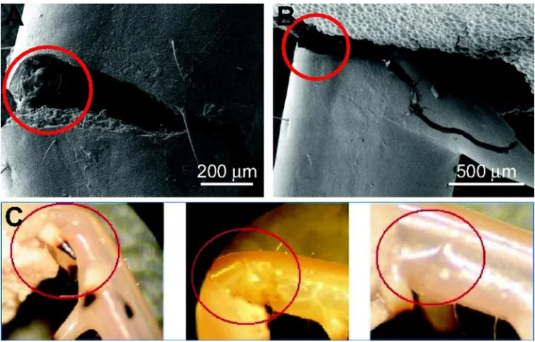
The present author and colleagues have investigated the tubes which form the legs of insects, crabs and humans (9-11). This work included the first ever fatigue tests of the materials from which insects and crabs are made: cuticle (11). We showed that fatigue occurs in cuticle samples from both legs and wings, but the fatigue range (i.e. the difference between the static strength and the fatigue limit) is relatively small in legs, probably due to the highly oriented, anisotropic fibrous structure, analogous to the behaviour of uniaxial fibre reinforced polymers. Interestingly, the samples used for fatigue testing these legs in cantilever bending displayed two different failure modes (see figure 5). Some samples failed in a classic fatigue mechanism involving the initiation and propagation of cracks starting in the region of highest tensile stress. However other samples failed by buckling on the compressive side of the tube. When samples were loaded monotically, failure almost always occurred by buckling. It was postulated
For Peer Review
that fatigue can lead to buckling-type failures as a result of viscoelasticity and creep in this material. During repeated cycling, the effective elastic modulus reduces over time to the point where either local buckling or ovalisation buckling becomes possible. It is not possible to distinguish between these two modes because they occur at almost the same applied stress in a circular tube.
It was found that these two different mechanisms of fatigue failure – tensile cracking and compressive buckling – occurred in approximately equal numbers in the test specimens. This suggests that the tube is in an optimal condition, being equally resistant to both types of failure. A tube of the same weight with a lower r/t ratio would tend to fail preferentially by cracking, whilst a tube of higher r/t would tend to fail by buckling. This suggests that evolution has succeeded in creating the optimal design for this particular tube. No other fatigue data exist for arthropod cuticle, though there are some static test results for the legs of crabs (12) which could be analysed using Wegst and Ashby’s approach (8). Considering the critical loading events in each case (jumping for the insect leg; walking under water for the crab leg) it was possible to show that the r/t ratios of these limbs represented the best possible compromise in relation to all possible failure modes (see figure 6). A different conclusion arises,
however, when considering the bones of humans and other vertebrates. These have r/t ratios which are much less than the optimal values, effectively reducing the fatigue and static strengths by about a factor of 2. This is because vertebrates have an internal skeleton - a so-called endoskeleton – which limits the maximum diameter of the bone and so prevents the use of thin-walled tubes as are found in those animals having exoskeletons.
The main lesson to be learned from Nature here is that, whilst tubular structures can be very
advantageous, their design is complex because of the various different failure mechanisms which arise, both in cyclic and monotonic loading. Nature is able to circumvent this problem by the trial-and-error
For Peer Review
method of evolution. Engineering designers need more precise methods of analysis, validated by extensive experimental testing, which can be incorporated into computer simulations. One of the current projects in the author’s research group is the development of test equipment able to apply pure bending to thin-walled tubes: such equipment is not readily available. Commercial finite element software does now allow predictions of buckling, though the analysis methods used need improvement and validation. From this experience it can be predicted that strength improvements of at least a factor of two are achievable as a result of better understanding of the fatigue behaviour of thin-walled hollow structures.
MONITORING AND REPAIR OF MICRODAMAGE
Fatigue involves the initiation and propagation of damage in the form of cracks. For high-cycle fatigue in particular there is great opportunity for extending the life of components by detecting cracks when they are still relatively small. Once detected these cracks may be repaired, or the cracked components may be replaced; in either case the advantage is that one can operate at stresses well above the endurance limit of the material. The aircraft industry has adopted this strategy, which is feasible in aircraft frames because the critical cracks are relatively long and so can be reliably detected during planned inspections. Other industries have been unable or unwilling to use this approach, with the result that most
components in vehicles are designed to be stressed below their endurance limits. The resulting conservatism gives rise to components which are much heavier than they would need to be if fatigue cracks could be repaired.
The ideal situation – the dream of materials engineers – would be a material which continuously monitors itself, and is able to detect and repair fatigue cracks when they are still microscopic in length. This dream is a reality for many natural materials. Bone is one such material; the cyclic stresses on our
For Peer Review
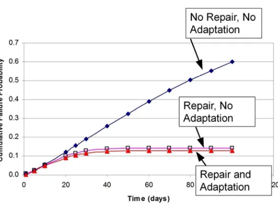
bones as a result of normal, daily activities are so high that fatigue failures would invariably occur within less than one year were it not for the continuous repair of microcracks. In recent years there has been extensive research into this phenomenon, driven by the needs of the medical profession to better understand diseases such as osteoporosis and to prevent sports injuries such as stress fractures (see for example (13) for a review on this subject). Bone is a quasibrittle material, comparable to engineering materials such as concrete and fibre composites. Fatigue failure involves the initiation of large numbers of microcracks, typically 100µm long. Most of these cracks become arrested at microstructural barriers (14): by the time fatigue failure occurs only 10-20% of these cracks will have overcome the first barrier, which is the osteon boundary (equivalent to the grain boundary in metals). A continuous repair system operates, involving the coordinated actions of different types of living cells, some of which remove regions of damaged bone by dissolving it in a powerful acid, whilst other cells create new bone to fill in the gap. It can be shown that these repair activities are not random, but rather are targeted towards areas where cracks exist, and tend to repair longer cracks preferentially (13). The author and colleagues have developed methods for predicting fatigue failure in bone including the effect of repair: figure 7 is an example illustrating the powerful effect of continuous repair (15). As yet it is not completely understood how cracks are detected, though it appears to be the responsibility of cells known as osteocytes, which live inside the bone material and are connected to each other in a continuous
network. A number of theories exist concerning how cracks might affect or disrupt this network (13; 16; 17).
Another very useful attribute of living organisms is pain. If a fatigue crack grows to a length of a few millimetres, threatening to cause a complete fracture of the bone, then this will be sensed by nerves inside the bone, giving rise to a pain signal. Doctors describe this as a “stress fracture”. The pain acts as a strong stimulus to cease using the limb, preventing further applications of force until the crack has been
For Peer Review
repaired. Maintenance engineers will greatly appreciate the potential advantages of a system which operates continuously, rather than periodically, and which has a much higher resolution than currently available in non-destructive inspection equipment. In a previous analysis (18) it was estimated that the advantages of this detection and repair system for bone amount to an effective increase in strength by a factor of 3.5, i.e. bone can be used at an operating stress which is 3.5 times higher than would be possible if it were a dead material, being used under normal engineering conditions.
Much work is being done at present in the development of intelligent materials capable of self-healing and condition monitoring, though to date the applications of such systems are limited by cost and the relatively small number of materials available. By contrast, the resolution of non-destructive crack-inspection equipment has hardly changed over the last few decades, being effectively limited to a few millimetres. This may be less to do with the technology involved and more about its practical application
in situ under challenging operating conditions.
A final word might be said about another important difference between engineering components and those in the natural world: Nature can accept high failure probabilities. For example, the probability of bone fractures among primates in the wild is 1-3% per bone per lifetime (19). Many of these fractures will lead to the death of the animal concerned, but this is acceptable because evolution works towards the survival of the species, not of the individual. Such high failure rates would be quite unacceptable in critical vehicle components, where reliabilities of one in a million are typically required. There is much scope in engineering design for a more careful consideration of failure probability. In most components the greatest uncertainties come from two factors: poor knowledge about operating stresses and the occurrence of manufacturing defects. Better information about these factors (even without any
For Peer Review
improvements in material quality) would allow designers to predict failure probabilities more accurately and thus avoid unnecessary conservatism in the design of failure-critical parts.
CONCLUSIONS
1. Taking inspiration from the branch joints of trees, stress concentration features such as corners with Kt factors of 2 or less can be virtually eliminated by the use of a variable-radius approach, greatly
increasing fatigue resistance.
2. Nature’s structural materials are fibre composites. Great potential exists for the improvement of components made from engineering fibre composites, with respect to features such as anisotropy, fibre insertions at joints and functional grading.
3. Nature uses additive manufacturing to create structures using a “bottom-up” approach from nano to macro scales. Future developments in additive manufacturing will allow engineers to make more sophisticated materials with hierarchical structures resistant to fatigue cracking, and components in which material structure and properties vary continuously, avoiding interfaces and joints.
4. Tubes are very common in Nature and in transport applications. Evolution has allowed Nature to develop tubes of optimal dimensions to resist competing fatigue failure modes such as tensile cracking and compressive buckling. Better understanding of these modes and their interactions will allow future engineering components to be made with considerable weight savings.
5. Nature’s materials are controlled and monitored by living cells, enabling continuous inspection and repair of microscopic damage. Future developments in self-healing materials and embedded sensors may allow engineers to approach this ideal in future components and structures for transport engineering.
For Peer Review
ACKNOWLEDGEMENTS
I’d like to acknowledge all the researchers from my group, past and present, who contributed to the work described above: their names are listed in the papers cited here. Funding from Science Foundation Ireland (grant number 08-RFP-ENM991) and the Irish Research Council is gratefully acknowledged.
FIGURE CAPTIONS
Figure 1: Fatigue failures can occur in trees: photo (a) shows a failure which has initiated at a branch junction and propagated downwards into the main trunk: note the darker area on the fracture surface indicating fatigue crack growth. However failures do not always occur at branch junctions, as shown in photo (b): here a tree trunk which broke during a storm has failed at a point remote from any branches. Failure modes typical of fibre composite materials can be seen: fibre pull-out in tension and buckling in compression.
Figure 2: A longitudinal section cut through a tree at a trunk/branch junction (photo reproduced
courtesy of Dr.Ulrich Muller, Linz, Austria). A circle has been drawn near the upper curve at the junction to illustrate that the curve does not have a constant radius.
Figure 3: An example of Mattheck’s method for reducing stress concentration (1). Here a feature with an initial Kt factor of 1.75 has been redesigned, making very slight changes to the local curvature. The Kt
factor has been reduced to 1.15 as a result.
Figure 4: Fatigue test data showing the improvement obtained by using a variable-radius curve at a 90o corner in a steel specimen loaded in cantilever bending (3). The constant-radius and variable radius specimens are shown: these were loaded in cantilever bending, clamping them on the right hand side and applying an upwards force to the left hand end.
For Peer Review
Figure 5: Examples of fatigue failures in insect legs subjected to cantilever bending (11). The two photos on the top line show crack initiation and propagation in the region of highest tensile stress. The three photos on the bottom line show buckling failures occurring on the compressive side.
Figure 6: An example of the prediction of failure modes and strengths for anisotropic tubes, applied in this case to the leg of a crab (for more details see (10)). The upper graph follows the method described by Wegst and Ashby (8) in which the normalised bending moment at failure is plotted for two different failure modes (fracture and buckling): the optimum r/t value occurs at the point where the two
prediction lines cross. The lower graph represents the same approach applied to axial compressive loading. Two different values arise for the optimum r/t, represented by the two vertical lines. The crab’s leg, which is loaded by approximately equal amounts of bending and compression, has an r/t value lying between these two predictions, indicating the best compromise solution.
Figure 7: Predictions of bone fatigue failure (15). The scenario being modelled is a person undertaking a period of strenuous exercise, e.g. someone joining the army or beginning a period of athletic training. The cumulative probability of a stress fracture occurring is plotted against time. Repair of microdamage by bone cells has a very strong effect in reducing the incidence of fractures. Adaptation (whereby bones alter their geometry in response to stress) has a small effect here, though it would have a larger effect in the long term.
References
1. Mattheck, C., Design in Nature: Learning from Trees, Springer, Berlin, 1998. 2. Peterson, R. E., Stress concentration factors, Wiley 1973.
3. Taylor, D., Kelly, A., Toso, M., and Susmel, L., "The variable-radius notch: Two new methods for reducing stress concentration," Engineering Failure Analysis, Vol. 18, No. 3, 2011, pp. 1009-1017.
For Peer Review
4. Reilly, D. T. and Burstein, A. H., "The elastic and ultimate properties of compact bone tissue,"
Journal of Biomechanics, Vol. 8, 1975, pp. 393-405.
5. Muller, U., Gindl, W., and Jeronimidis, G., "Biomechanics of a branch-stem junction in softwood,"
Trees, 2006, pp. 643-648.
6. Nalla, R. K., Kruzic, J. J., Kinney, J. H., and Ritchie, R. O., "Effect of aging on the toughness of human cortical bone: Evaluation by R-curves," Bone, Vol. 35, No. 6, 2004, pp. 1240-1246. 7. Brazier, L. G., Proceedings of the Royal Society of London, Vol. 116, 1927, pp. 104.
8. Wegst, U. G. K. and Ashby, M. F., "The structural efficiency of orthotropic stalks, stems and tubes," Journal of Materials Science, Vol. 42, 2007, pp. 9005-9014.
9. Dirks, J. H. and Taylor, D., "Fracture toughness of locust cuticle," Journal of Experimental Biology, Vol. 215, No. 9, 2012, pp. 1502-1508.
10. Taylor, D. and Dirks, J. H., "Shape optimization in exoskeletons and endoskeletons: A
biomechanics analysis," Journal of the Royal Society Interface, Vol. 9, No. 77, 2012, pp. 3480-3489. 11. Dirks, J. H., Parle, E., and Taylor, D., "Fatigue of insect cuticle," Journal of Experimental Biology,
Vol. 216, No. 10, 2013, pp. 1924-1927.
12. Hahn, K. and LaBarbera, M., "Failure of limb segments in the blue crab callinectes sapidus (crustacea: malacostraca)," Comp.Biochem.Physiol., Vol. 105A, 1993, pp. 735-739.
13. Taylor, D., Hazenberg, J. G., and Lee, T. C., "Living with Cracks: Damage and Repair in Human Bone," Nature Materials, Vol. 2, 2007, pp. 263-268.
14. O'Brien, F. J., Taylor, D., and Lee, T. C., "The effect of bone microstructure on the initiation and growth of microcracks," Journal of Orthopaedic Research, Vol. 23, No. 2, 2005, pp. 475-480. 15. Taylor, D., Casolari, E., and Bignardi, C., "Predicting stress fractures using a probabilistic model of
damage, repair and adaptation," Journal of Orthopaedic Research, Vol. 22, 2004, pp. 487-494. 16. Taylor, D., Hazenberg, J. G., and Lee, T. C., "The cellular transducer in bone: what is it?,"
Technology and Health Care, Vol. 14, 2006, pp. 367-377.
17. Dooley, C., Tisbo, P., Lee, T. C., and Taylor, D., "Rupture of osteocyte processes across microcracks: The effect of crack length and stress," Biomechanics and Modeling in Mechanobiology, Vol. 11, No. 6, 2012, pp. 759-766.
18. Taylor, D., "What we can't learn from nature," Materials Science and Engineering C, Vol. 31, No. 6, 2011, pp. 1160-1163.
19. Currey, J., Bones: Structure and Mechanics, Princeton University Press, USA 2002.
For Peer Review
[image:18.612.118.495.111.362.2]Figure 1: Fatigue failures can occur in trees: photo (a) shows a failure which has initiated at a branch junction and propagated downwards into the main trunk: note the darker area on the fracture surface indicating fatigue crack growth. However failures do not always occur at branch junctions, as shown in photo
(b): here a tree trunk which broke during a storm has failed at a point remote from any branches. Failure modes typical of fibre composite materials can be seen: fibre pull-out in tension and buckling in
compression. 88x58mm (300 x 300 DPI)
For Peer Review
A longitudinal section cut through a tree at a trunk/branch junction (photo reproduced courtesy of Dr.Ulrich Muller, Linz, Austria). A circle has been drawn near the upper curve at the junction to illustrate that the
curve does not have a constant radius. 98x152mm (300 x 300 DPI)
For Peer Review
An example of Mattheck’s method for reducing stress concentration (1). Here a feature with an initial Kt factor of 1.75 has been redesigned, making very slight changes to the local curvature. The Kt factor has
been reduced to 1.15 as a result. 107x49mm (300 x 300 DPI)
For Peer Review
Figure 4: Fatigue test data showing the improvement obtained by using a variable-radius curve at a 90o corner in a steel specimen loaded in cantilever bending (3). The constant-radius and variable radius specimens are shown: these were loaded in cantilever bending, clamping them on the right hand side and
applying an upwards force to the left hand end. 103x62mm (300 x 300 DPI)
For Peer Review
[image:22.612.118.494.111.352.2]Figure 5: Examples of fatigue failures in insect legs subjected to cantilever bending. The two photos on the top line show crack initiation and propagation in the region of highest tensile stress. The three photos on the
bottom line show buckling failures occurring on the compressive side 91x57mm (300 x 300 DPI)
For Peer Review
Figure 6: An example of the prediction of failure modes and strengths for anisotropic tubes, applied in this case to the leg of a crab (for more details see (10)). The upper graph follows the method described by Wegst and Ashby (8) in which the normalised bending moment at failure is plotted for two different failure
modes (fracture and buckling): the optimum r/t value occurs at the point where the two prediction lines cross. The lower graph represents the same approach applied to axial compressive loading. Two different values arise for the optimum r/t, represented by the two vertical lines. The crab’s leg, which is loaded by
approximately equal amounts of bending and compression, has an r/t value lying between these two predictions, indicating the best compromise solution.
228x369mm (300 x 300 DPI)
For Peer Review
Figure 7: Predictions of bone fatigue failure (15). The scenario being modelled is a person undertaking a period of strenuous exercise, e.g. someone joining the army or beginning a period of athletic training. The cumulative probability of a stress fracture occurring is plotted against time. Repair of microdamage by bone
cells has a very strong effect in reducing the incidence of fractures. Adaptation (whereby bones alter their geometry in response to stress) has a small effect here, though it would have a larger effect in the long
term.
79x44mm (300 x 300 DPI)