A Comparative Study of the Performance of
Seven-and 63-Chip Optical Code-Division Multiple-Access
Encoders and Decoders Based on Superstructured
Fiber Bragg Gratings
Peh Chiong Teh, Member, OSA, Periklis Petropoulos, Member, OSA, Morten Ibsen, Member, OSA, and
David J. Richardson
Abstract—We report a range of elementary optical coding and decoding experiments employing superstructured fiber Bragg grating (SSFBG) components. First, we perform a com-parative study of the relative merits of bipolar and unipolar coding : decoding schemes and show that the SSFBG approach allows high-quality unipolar and bipolar coding. A performance close to that theoretically predicted for seven-chip, 160-Gchip/s -sequence codes is obtained. Second, we report the fabrication and performance of 63-chip, 160-Gchip/s, bipolar Gold sequence grating pairs. These codes are at least eight times longer than those generated by any other scheme based on fiber grating technology so far reported. Last, we describe a range of transmission system experiments for both the seven- and 63-bit bipolar grating pairs. Error-free performance is obtained over transmission distances of 25 km of standard fiber. In addition, we have demonstrated error-free performance under multiuser operation (two simulta-neous users). Our results highlight the precision and flexibility of our particular grating writing process and show that SSFBG technology represents a promising technology not just for optical code division multiple access (OCDMA) but also for an extended range of other pulse-shaping optical processing applications.
Index Terms—All-optical process, code division multiple access (CDMA), communication systems, fiber Bragg gratings (FBGs), multiple-access communications, optical networks, optical signal processing.
I. INTRODUCTION
T
HE EXPLOSIVE growth of the Internet over recent years has placed increasing demands on both the capacity and the functionality of optical transmission systems and networks. Most work to date has focused on the use of wave-length division multiplexing (WDM), optical time-division multiplexing (OTDM), or a hybrid approach to achieve the ter-abit-per-second aggregate channel capacity required. Now that terabit-per-second systems have been demonstrated in the labo-ratory, interest is beginning to grow in investigating alternative multiplexing schemes such as optical code division multiple access (OCDMA) that can further enhance the functionality of optical networks [1]–[14]. CDMA is a spread-spectrum technique that permits a large number of separate users to share the same extended transmission bandwidth but to beManuscript received August 21, 2000; revised April 19, 2001.
The authors are with the Optoelectronics Research Centre, Southampton Uni-versity, Southampton SO17 1BJ, U.K. (e-mail: [email protected]).
[image:1.612.318.539.223.394.2]Publisher Item Identifier S 0733-8724(01)07759-3.
Fig. 1. Outline of the physical approach of pulse encoding and decoding using superstructured fiber Bragg gratings (SSFBGs).
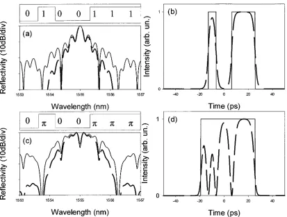
Fig. 2. Schematic examples of temporal codes (upper traces) and corresponding refractive index modulation profiles along the SSFBG structures (lower traces). (a) A unipolar code (M7U-1). (b) A bipolar code (M7B-1). (c) The matched filter to M7U-1 (M7U-1 ). For the cases described in our experiments, the period of the refractive index modulation was
1 = 520 nm and the chip length L = 0:66 mm.
[image:1.612.323.532.433.679.2]Fig. 3. (a) Calculated reflectivity spectrum (solid line) and spectral response to 2.5-ps soliton pulses (dashed line) for the unipolar grating M7U-1. (b) Calculated impulse response (solid line) and temporal response to 2.5-ps soliton pulses (dashed lines) for the grating M7U-1. (c) Calculated reflectivity spectrum (solid line) and spectral response to 2.5-ps soliton pulses (dashed line) for the bipolar grating M7B-1. (d) Calculated impulse reponse (solid line) and temporal response to 2.5-ps soliton pulses (dashed lines) for the grating M7B-1.
individually addressable through the allocation of specific address codes [15]. The encoding can be performed either in the time domain [direct-sequence (DS-CDMA)] or frequency domain [frequency-hopping (FH-CDMA)]. In DS-CDMA, each data bit to be transmitted is defined by a code composed of a sequence of pulses. The individual pulses comprising the coded bit are commonly referred to as chips. The coded bits are then broadcast onto the network but are only received by users with a receiver designed to unambiguously recognize data bits of the given specific address code. Address-code recognition is ordinarily achieved by simple matched filtering within the receiver. By contrast, in FH-CDMA, the carrier frequency of the chips (or bits) is changed according to a well-defined code sequence that can once again be suitably identified by an appropriate receiver. The technique has been applied with great success to the field of mobile communications but has only recently generated significant interest in the optical domain. The particular attractions of OCDMA include the capacity for higher connectivity, more flexible bandwidth usage, higher granularity and scalability within optical networks, improved crosstalk performance, asynchronous access, and potential for improved system security.
OCDMA technology is still at a relatively immature stage of development. A key issue relates to how to reliably generate and recognize appropriate code sequences. (The issue of what con-stitutes an appropriate code sequence is described within a later
section of this paper.) To date, the most common approach is to use arrays of discrete optical waveguide-based delay lines to temporally, or sometimes spectrally, manipulate the individual data bits in order to perform the coding and decoding process. In the earliest implementations, the delay lines used were simple optical fibers of different lengths appropriately coupled together using fiber couplers [1], [2]. However this approach is not a practical solution due to its limited scalability and the difficulty in obtaining and maintaining adequate accuracy on the length of the individual delay lines. More recently, planar lightwave circuits (PLCs) have been used to overcome the limiting prac-tical issues discussed above by monolithically integrating the re-quired tunable taps, phase-shifters, and combiners onto a single substrate [3]. Another PLC technology, the arrayed waveguide grating (AWG), has also been investigated for OCDMA applica-tions [4]. While this is indeed a more practical approach, PLCs are difficult and expensive to fabricate and are therefore a far from ideal technical solution. However, it should be appreciated that this technology is still very attractive despite these draw-backs since it allows for tunable encoders and decoders.
short pulse. A spatial amplitude–phase mask can then be used to perform the necessary filtering functions and to reshape the pulse [5]–[7]. However, the approach is again of somewhat lim-ited practical value due not least to lack of compactness, spec-tral/temporal resolution, and cost.
[image:3.612.324.533.70.385.2]More recently, single-beam encoding and decoding schemes based on fiber Bragg grating (FBG) technology have been pro-posed and demonstrated. The most straightforward approach is to use an array of FBGs written or spliced in a sequence along a single fiber line [8], [9]. The spatial position of the gratings and their associated reflection profiles can then be used to encode both temporal and spectral information onto an incident data pulse. For example, a form of fast frequency-hop OCDMA has recently been demonstrated in which the central wavelength of sequential gratings in an encoder–decoder grating array is varied so as to define individual chips within the code [8]. This particular example exploits the wavelength selectivity of the individual gratings and the positioning of the gratings within the array in only a relatively coarse way, i.e., in terms of a time-of-flight delay. However, grating technology has progressed to the point that the optical phase of light reflected from individual gratings can also be exploited, allowing the use of optical phase as a coding parameter (note that this is already possible using PLC technology [3]). Use of phase coding is significant since it is well known that bipolar codes exhibit far better cross-correlation/crosstalk characteristics than amplitude only unipolar codes. This key aspect of phase encoding allows lower interchannel interference, and thus more simultaneous users for a given code length (and associated optical bandwidth) than unipolar coding. This ultimately permits a higher overall system spectral efficiency relative to unipolar coding, which is known to give relatively poor performance in this regard relative to conventional WDM and WDM/TDM [10]. It is also worth noting that the use of two-dimensional (2-D) matrix coding schemes, where more than one parameter is coded (e.g., both phase and amplitude), can also be used to improve code discrimination and to provide still further benefits in terms of multiuser operation and increased spectral efficiency [10]–[12]. However, a detailed discussion of 2-D coding is beyond the scope of this paper. The use of bipolar codes with FBG technology was first demonstrated using a segmented FBG array that comprised uniform period gratings with an accurately controlled phase (path length) between individual gratings [13]. The phase mask used to imprint the grating into the fiber defined the precision of the grating structure in this experiment, which places significant practical limits on the length and accuracy with which such an array could be written, as well as the flexibility in writing gratings with different codes. We previously proposed and demonstrated the use of super-structured fiber Bragg gratings (SSFBGs) to provide an alterna-tive approach to the discrete FBG array based pulse encoders and decoders discussed above [14] (see Fig. 1 for a picture outlining the physical approach). Over the past few years, we have developed a continuous grating writing technique at the University of Southampton that allows the possibility of essen-tially continuous amplitude and phase control along an indi-vidual grating structure [16]. This particular technique is attrac-tive in that it is far more flexible from a fabrication perspecattrac-tive
Fig. 4. Calculated traces of the decoded signals for 2.5-ps soliton input pulses for the grating combinations: (a) M7U-1 : M7U-1 and (b) M7B-1 : M7B-1 .
than other techniques so far demonstrated and therefore allows for a far broader range of codes and potential coding schemes. Most significantly, it is also not bounded by the current reso-lution limits and device lengths imposed by phase mask tech-nology and offers great potential for the production of low-cost devices. However, to date, there have been few experiments to assess the true potential, performance limits, and scalability of the SSFBG approach within OCDMA applications.
In this paper, we report on the results of upgrading the su-perstructure approach to encompass bipolar as well as unipolar coding, higher data rates (10 Gb/s), shorter chip lengths (6.4 ps), and far longer code sequences (63 b) than previously demon-strated. This paper is organized as follows. In Section II, we outline the theoretical background and present simulations of the encoding and decoding schemes demonstrated in the later sections of this paper. In Section III, we describe our experi-mental setup and describe also the gratings fabricated for use within our experiments. In Section IV, we present the results of our various optical code generation and recognition experiments and show results from preliminary transmission experiments. In Section V, we draw conclusions regarding this specific work and discuss further extensions and applications of this powerful new technology to optical network applications.
II. THEORETICALBACKGROUND
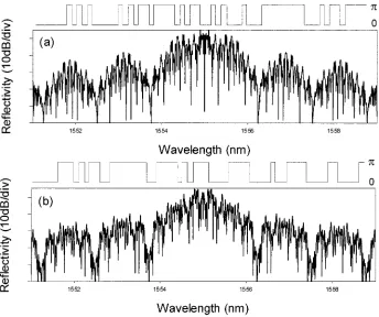
ampli-Fig. 5. Superstructure profiles (upper traces) and corresponding calculated reflectivity spectra (lower traces) for (a) G63B-1 and (b) G63B-2.
tude and pitch, onto which an additional, slowly varying refrac-tive index modulation profile has been imposed along its length. In the weak SSFBG grating limit, i.e., where the grating strength is such that light penetrates the full grating length and the indi-vidual elements of the grating contribute more or less equally to the reflected response, the wavevector response can be shown to be given simply by the Fourier transform of the spatial superstructure refractive index modulation profile used to write the grating [17], for example
(1)
The uniform rapid refractive index modulation simply defines the central frequency/wavelength of the grating’s reflection band. Similarly, the impulse response of a fiber grating is given by the inverse Fourier transform of its frequency response
(2)
From the above equations and the fact that the wavevector is proportional to the optical frequency , it is clear that the im-pulse response of a weak grating has a temporal profile given by the complex form of the refractive index superstructure modu-lation profile of the grating. For example, in the instance that the grating superstructure is simply amplitude modulated, i.e., the grating phase is uniform (we refer to such gratings as unipolar coded herein), the impulse response follows precisely the am-plitude modulation profile used to write the grating [14]. (The scaling factor is used to convert from the spatial to
temporal domain, where is the refractive index and is the speed of light.)
When a short but finite bandwidth pulse (i.e., not an impulse pulse) is reflected from an SSFBG, it is transformed into a pulse with a temporal shape given by the convolution between the input pulse and the impulse response of the grating, i.e.,
(3)
the process is described in the frequency domain by the product of the Fourier transform of the incident signal with the frequency response of the grating
(4)
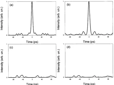
[image:4.612.124.468.71.359.2]Fig. 6. Calculated traces of the signals after the code : decode process for 2.5-ps soliton input pulses for the grating combinations: (a) G63B-1 : G63B-1 , (b) G63B-2 : G63B-2 , (c) G63B-2 : G63B-1 , and (d) G63B-1 : G63B-2 .
Fig. 7. Experimental setup (EDFA: erbium-doped fiber amplifier; LCFBG: linearly chirped fiber Bragg grating).
In Fig. 3(a) and (b), we plot the theoretical impulse response and optical power reflectivity spectrum of the unipolar grating (M7U-1) shown in Fig. 2(a) and the resulting reflected optical power spectrum and temporal response after excitation with 2.5-ps soliton pulses (dashed lines). We present the corre-sponding plots for the bipolar grating shown in Fig. 2(b) in Fig. 3(c) and (d). The relations between the superstructure refractive index modulation profiles and the gratings’ temporal
response are clear for both grating modulation formats. The reduced temporal feature resolution, and additional code-se-quence amplitude profiling, due to the use of finite bandwidth optical pulses to excite the gratings are also apparent within Fig. 3.
TABLE I
DIFFERENTTYPES OFSSFBGs USED IN THEEXPERIMENTS
and associated impulse response . In the frequency domain, the overall response of the system is given by
(5)
from which it is clear that if we use impulse response
excita-tion of the encoder grating and set ,
then is the autocorrelation function of the superstructure profile used to write the encoder grating with the impulse re-sponse of the decoder grating, . Physically, this requirement dictates that the superstructure function of the de-coder grating is the spatially reversed form used to write the encoder grating [see Fig. 2(a) and (c)]. Our principle of pattern recognition is thus nothing more than simple matched filtering. Note that if is different from , then the resultant waveform represents the cross-correlation function of the two different grating superstructure profiles (codes). Note also that
has a total temporal length of two times the code length. To achieve good high-contrast code recognition, one needs to restrict the use of codes within the system to those that have both distinct autocorrelation features with a single dominant, well-defined autocorrelation peak and low peak-level mutual cross-correlation functions. This requirement also exists within radio-based direct-sequence CDMA, and the chip patterns used are usually the well-known -sequences, or are based on com-binations of -sequences such as Gold codes, Kassami codes, or Walsh–Hadamard codes, which are known to have such prop-erties [18], [19]. Such codes are also applicable to OCDMA. The quality of the code recognition and the number of “orthogonal” codes supported by a given code length is a strong function of the code length and degree of polarity (i.e., the number of pos-sible coding levels) of the implementation. Both of these prop-erties improve significantly with the use of longer codes and increasing degrees of polarity.
[image:6.612.327.528.276.582.2]To explicitly illustrate these features, we plot in Fig. 4(a) and (b) the response of the decode gratings to the pulse patterns generated from the relevant encoder grating after they have themselves been excited with 2.5-ps pulses [see Fig. 3(b) and (d), respectively]. In both instances, a well-defined pulse-form is obtained with a single distinct autocorrelation feature.
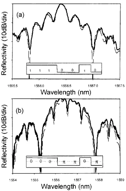
Fig. 8. Reflectivity spectra for (a) the M7U-1 and (b) the M7B-1 grating (solid lines: experimental measurements; dashed lines: theoretical plots).
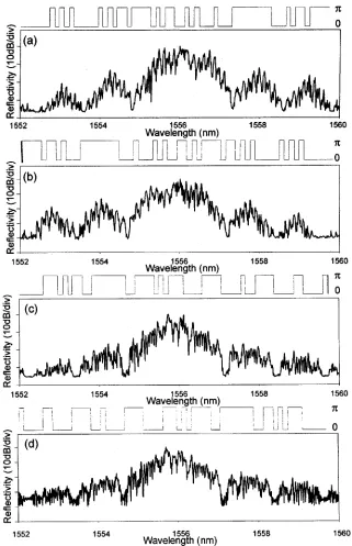
Fig. 9. Superstructure profiles (upper traces) and the corresponding measured reflectivity spectra (lower traces) for (a) G63B-1, (b) G63B-1 , (c) G63B-2, and (d) G63B-2 .
For an -chip Gold sequence, there are 2 such “or-thogonal” codes [18]. In Fig. 6, we plot the theoretically predicted responses resulting from the code : decode process for 2.5-ps input pulses for the following combinations of coding and decoding gratings: G63B-1 : G63B-1 [Fig. 6(a)] and G63B-2 : G63B-1 [Fig. 6(c)], while G63B-2 : G63B-2 [Fig. 6(b)] and G63B-1 : G63B-2 [Fig. 6(d)]. The form of labeling indicates grating for the encoder and the conjugate grating of grating as the decoder. This labeling convention will be used throughout the remainder of this paper. Comparing Figs. 4 and 6, it is immediately appreciated that the use of the longer code sequence provides
much better autocorrelation contrast than is achievable with a seven-bit code. Moreover, the absence of any significant peak on the cross-correlation profile also shows that much higher pulse-code discrimination can be achieved.
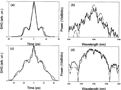
Fig. 10. (a) Intensity SHG autocorrelation traces of the encoded waveforms for the M7U-1 grating, for 2.5-ps soliton input pulses. (b) Spectral response of the encoded waveforms for the M7U-1 grating. (c) Intensity SHG authocorrelation traces of the encoded waveforms for the M7B-1 grating, for 2.5-ps soliton input pulses. (d) Spectral response of the encoded waveforms for the M7B-1 grating. Solid lines represent experimental measurements, whereas dashed lines represent theoretical plots. The 10-GHz periodic structure on the spectral envelope of the experimental measurements results from the 10-Gb/s modulation of the signal.
III. EXPERIMENTALSETUP
Our basic experimental setup is shown in Fig. 7 and com-prises:
1) an externally modulated, mode-locked soliton fiber laser; 2) means for coupling light onto and off of one or more
coding gratings;
3) means to couple the individual codes together into a single fiber;
4) a transmission line with associated dispersion compensa-tion;
5) a decoder grating to perform the code recognition.
Amplifiers were incorporated within the system at appropriate positions to compensate for the various sources of loss such as the transmission line, optical circulator insertion loss, and cou-pler splitting ratios. The transmitter (soliton laser external modulator) could be used to generate continuous pulse trains of 2.0–2.5ps, transform limited soliton pulses at predetermined fre-quencies in the range 0.5–10 GHz, or pseudorandom data at pre-determined data rates in the range 1–10 Gb/s. This data stream was then coded using an SSFBG and either decoded immedi-ately using a matched grating or transmitted over some distance, and then decoded. The pulse-shaping properties (temporal and spectral), and bit error rate (BER) performance at various points throughout the system were characterized using:
1) a fast pin-diode and sampling scope of 20 GHz com-bined bandwidth;
2) a second harmonic generation (SHG) autocorrelator ( 100 fs resolution);
3) an optical spectrum analyzer;
4) where appropriate, a 10-Gb/s receiver and BER test set (BERT).
Fig. 11. Traces of the encoded waveforms for (a) the G63B-1 and (b) the G63B-1 grating, for 2.5-ps soliton input pulses. Solid lines represent experimental measurements, whereas dashed lines represent theoretical plots. The detection bandwidth of the experimental measurement (20 GHz) was not taken into account for the theoretical calculation.
grating fabrication techniques, where the induced refractive index pattern is written into the phase mask itself and simply imprinted into the fiber. The conventional approach limits both the quality and the length of the gratings that can be written to those that can be achieved for current phase-mask production itself, which is considerably inferior to what can be achieved using our FBG writing technique. The practical benefits of our approach regarding flexibility, manufacturability, and grating quality should be self-evident.
SSFBGs are obtained by modulating the slowly varying am-plitude–phase envelope (on the rapidly varying) refractive index profile of an otherwise uniform grating. As discussed previ-ously, the impulse response of a weakly reflecting SSFBG (re-flectivity typically 20%) is given directly by the superstructure modulation profile used to write the grating. The unipolar grat-ings (M7U-1, M7U-1 ) were similar in design to those used in the earlier experiments [14], only physically shorter in length. The total grating length in each instance was 4.63 mm (corre-sponding to a temporal code duration of 44.8 ps) and the in-dividual chip width was 0.66 mm (corresponding to a temporal chip length of 6.4 ps versus 200 ps in our earlier experiments). The amplitude-modulated superstructure profiles used to write the unipolar code gratings (M7U-1, M7U-1 ) are shown in the inset with the corresponding theoretical and experimental power reflectivity profiles in Fig. 8(a). The bipolar grating (M7B-1, M7B-1 ) designs are shown in Fig. 8(b). They are pure phase-encoded structures with discrete phase shifts at the (nonre-turn-to-zero) chip transition boundaries. The experimental and theoretical plots are shown in Fig. 8(a) and (b). The agreement between the theoretical and experimental spectral responses of both sets of seven-bit SSFBG types is seen to be excellent, high-lighting the precision of our grating writing process. Note that the absolute reflectivity of the M7B gratings is 50% (due to
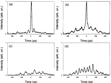
[image:9.612.324.533.374.681.2]Fig. 13. Traces of the signals after the code : decode process for 2.5-ps soliton input pulses, for the grating combinations: (a) G63B-1 : G63B-1 , (b) G63B-2 : G63B-2 , (c) G63B-2 : G63B-1 , and (d) G63B-1 : G63B-2 . The detection bandwidth was20 GHz.
the use of a higher photosensitivity fiber), which is significantly higher than the quoted upper limit generally considered for the weak-grating Fourier design approach to be reliable. However, even at this higher level of reflectivity, the gratings are still found to perform well.
The second sets of encoding : decoding gratings to be pro-duced were nominally identical to the seven-bit bipolar encoded gratings of Fig. 8 in terms of chip length ( mm ps) and wavelength, only much longer both in terms of number of chips (63) and correspondingly physical length ( 42 mm), and were made to the theoretical designs shown in Fig. 5. Four specific gratings were made: G63B-1, G63B-1 , G63B-2, and G63B-2 , as shown in Fig. 9. The purpose of producing these gratings was to determine whether coherency of the grating process could be maintained over increased grating length, to make a more sensible assessment of the achievable minimum levels of code cross-correlation, and to allow a preliminary assessment of the system penalties associated with multiuser operation.
IV. EXPERIMENTALRESULTS
A. Optical Code Generation
To assess the quality of the individual gratings, we first per-formed a series of code-generation experiments and examined both the temporal and spectral characteristics of pulse forms generated on reflection from the individual code gratings. In Fig. 10, we plot the temporal response of gratings M7U-1 and M7B-1 as measured using the SHG autocorrelator along with the corresponding optical spectra. The measured
autocorrela-tions and spectral forms are found to be in excellent agreement with the theoretical predictions within the resolution limits of the respective measurements, confirming the formation of the correct code patterns and the desired chip duration of 6.4 ps.
The equivalent temporal domain measurements for the longer gratings G63B-1 and G63B-1 are shown plotted in Fig. 11. In this instance, due to the use of longer code sequences, direct electronic measurements are of value since despite the 20-GHz bandwidth limitation, one can still discern features on the wave-form associated with the chip structure of the individual codes. Good qualitative agreement between experiment and theory are evident. From the plots, it can readily be resolved that the im-pulse response of G63B-1 is close to the time reversed response of G63B-1 as required for good matched filter operation. Impor-tantly, these experiments confirm that we are able to maintain good coherence within our gratings along lengths in excess of 40 mm.
B. Code Recognition
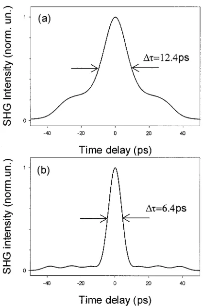
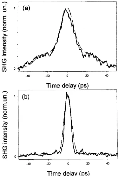
Fig. 14. Intensity SHG autocorrelation traces of the signals after code : decode process for 2.5-ps soliton input pulses for the 63-bit grating combinations: (a) G63B-1 : G63B-1 and (b) G63B-2 : G63B-2 . Solid lines represent experimental measurements, whereas dashed lines represent theoretical plots.
The results of the equivalent temporal measurements made with the electronic detection system for the 63-bit code grating pairs G63B-1, G63 B-1 and G63B-2, G63B-2 are summarized in Fig. 13(a) and (b), where the clarity of the autocorrelation is as expected, and even more distinct due to the larger number of chips within the code. The height of the autocorrelation spike is predicted to increase as , where is the code length. In Fig. 13(c), we plot the result of the coding : decoding process for two different Gold codes, i.e., G63B-1 : G63B-2 . As can be seen, no distinct correlation spike is observed, as expected for the case of two Gold codes. Similar results were obtained for the G63B-2 : G63B-1 case, as shown in Fig. 13(d). Fig. 14(a) and (b) shows the SHG autocorrelations of code recognition for G63B-1 : G63B-1 and G63B-2 : G63B-2 against theoret-ical calculations. Again, close to theorettheoret-ical performance can be seen with a peak pulse width of 6.4 ps for both cases.
C. System Characterization
[image:11.612.301.554.73.262.2]To quantify the quality of our results from a system perspec-tive, we performed a number of encoding : decoding and trans-mission BER experiments. The transtrans-mission line used within these experiments was composed of 25 km of standard SMF-28 grade fiber, with 0.2 dB/km loss. The high dispersion of this fiber ( 20 ps/nm/km) was compensated for using a chirped fiber grating of opposite and nominally equal dispersion at the system operating wavelength of 1557.5 nm with a full band-width of 5 nm. A plot of the dispersion-compensating grating
Fig. 15. Reflectivity spectrum of the dispersion-compensating grating. The time delay diagram is shown in the inset.
Fig. 16. BER curves for the M7B-1 : M7B-1 combination (open circles: laser back-to-back; closed circles: decoded signal without transmission; triangles: decoded signal after transmission). Inset shows eye diagrams of the decoded signals without (upper trace) and with transmission (lower trace). The data rate was 10 Gb/s.
response is shown in Fig. 15. Note that previous work has in-dicated that dispersion-slope correction can in certain instances also be an issue for such broadband spread-spectrum transmis-sion schemes since it can serve to skew the chip alignment in the decoded signal [21]. No such effects were apparent in our cur-rent experiments; however, it should be appreciated that third-order dispersion compensation can also be incorporated into the design of dispersion compensating Bragg gratings if required [22], [23]. As mentioned previously, the dispersion compen-sating grating used in our experiments was also fabricated using the same technique and with the same phase mask used to fab-ricate the coding/decoding SSFBGs.
[image:11.612.312.545.311.486.2]Fig. 17. BER curves for the G63B-1 : G63B-1 combinations (closed circles: laser back-to-back; closed squares: no transmission; open squares: after transmission; closed triangles: with second channel present and no transmission; open triangles: with second channel present and transmission). The data rate was 1.25 Gb/s.
is observed relative to the back-to-back transmitter measure-ments, nor is the appearance of any temporal features away from the chip-length-long correlation peak. Note that the width of the pattern-recognition trace is two times the total code length, i.e., 89.6 ps, just less than the bit period of 100 ps.
In Fig. 17, we plot BER curves for the G63B-1 : G63B-1 grating pair encode : decode process along with results for the associated 25-km transmission. These measurements were made at a bit rate of 1.25 Gb/s to ensure no temporal overlap of adjacent decoded correlation pulses. Error-free performance can be obtained for the code : :decode process both with and without transmission and with minimal power penalty between both cases. However, there is a power penalty of 1.5 dB between the laser back-to-back measurement with the code : decode process. Also included in Fig. 17 is a curve showing the results of experiments in which we simultaneously generated code sequences using gratings G63B-1 and G63B-2 and combined them together before decoding the combined channels with G63B-1 . The power in each individual channel at the receiver was identical. This measurement is also per-formed with the 25-km transmission inserted between encoding and decoding. We could thus investigate the impact of inter-channel crosstalk. We obtained error-free performance with minimal power penalty with and without transmission. The apparent noise penalty of 3 dB observed when comparing the G63B-1 : G63B-1 case (with and without transmission) with the two-channel case (G63B-1 and G63B-2:G63B-1 both with and without transmission) results primarily from the increased average power due to the addition of the second interference channel, although a contribution also arises due to coherent interference noise between the individual code sequences. Nevertheless, we could still obtain the excellent code discrimination using these gratings.
From a systems perspective, it is clearly essential that multi-channel interference noise is minimized to as great an extent as is possible. The obvious routes to doing this are as follows.
1) Making the best possible choice of “orthogonal” codes. Using longer code sequences can help in this regard, as can increasing the coding complexity, e.g., the use of higher levels of phase encoding, or the use of 2-D ma-trix codes.
2) Implementing some form of nonlinear optical thresh-olding at the receiver to eliminate the low-level cross-cor-relation signals generated by “decoding” the unmatched codes. For example, using a nonlinear loop mirror, we were recently able to largely eliminate both inter-channel and intrainter-channel interference noise effects in a two-channel OCDMA system [24]. We are still in the process of establishing precisely how many simultaneous users our 63-chip bipolar grating approach can reliably accommodate. However, from our very latest experi-ments [24], and on the basis of earlier theoretical works [5], our current best estimate is that it should be possible to get good system operation with 10–20 simultaneous users, each operating at a data rate of 1.25 Gb/s.
V. CONCLUSION
than previously demonstrated, and have obtained good agree-ment with theoretical expectations. Finally, we have performed a number of elementary system measurements of the code se-quences, both back to back and over a 25-km transmission line. The experiments show there to be little, if any, power penalty as-sociated with the coding : decoding and transmission processes for individual codes. Moreover, we have demonstrated error-free performance under multiuser operation (two simultaneous users). Our results highlight the precision and flexibility of our par-ticular grating writing process and show that SSFBG technology represents a promising technology both for OCDMA and for an extended range of other pulse-shaping optical processing appli-cations [25], [26]. However, it should be appreciated that the OCDMA experiments reported herein are still relatively ele-mentary and that considerable further work is required to es-tablish the commercial viability/practicality of the approach. For example, key issues that need further investigation include determining the true extent that significant simultaneous mul-tiuser capability can be supported and the reproducibility of the SSFBG coder/decoder grating fabrication process.
ACKNOWLEDGMENT
The authors wish to acknowledge useful past input from A. Fu, H. Geiger, M. N. Zervas, and R. I. Laming.
REFERENCES
[1] P. R. Prucnal, M. A. Santoro, and T. R. Fan, “Spread spectrum fiber-optic local area network using optical processing,” J. Lightwave Technol., vol. LT-4, pp. 547–554, 1986.
[2] M. E. Marhic, “Coherent optical CDMA networks,” J. Lightwave
Technol., vol. 11, pp. 854–863, June 1993.
[3] N. Wada and K. Kitayama, “A 10Gb/s optical code division multiplexing using 8-chip optical bipolar code and coherent detection,” J. Lightwave
Technol., vol. 17, pp. 1758–1765, Oct. 1999.
[4] H. Tsuda, H. Takenouchi, T. Ishii, K. Okamoto, T. Goh, K. Sato, A. Hi-rano, T. Kurokawa, and C. Amano, “Spectral encoding and decoding of 10 Gbit/s femtosecond pulses using high resolution arrayed-waveguide grating,” Electron. Lett., vol. 35, pp. 1186–1187, July 8, 1999. [5] J. A. Salehi, A. M. Weiner, and J. P. Heritage, “Coherent ultrashort light
pulse CDMA communication systems,” J. Lightwave Technol., vol. 8, pp. 478–491, Apr. 1990.
[6] H. P. Sardesai, C. C. Chang, and A. M. Weiner, “A femtosecond code division multiple-access communication system test bed,” J. Lightwave
Technol., vol. 16, pp. 1953–1964, Nov. 1998.
[7] T. Dennis and J. F. Young, “Optical implementation of bipolar codes,”
IEEE J. Quantum Electron., vol. 35, pp. 287–291, Mar. 1999.
[8] H. Fathallah, L. A. Rusch, and S. LaRochelle, “Passive optical fast fre-quency-hop CDMA communications system,” J. Lightwave Technol., vol. 17, pp. 397–405, Mar. 1999.
[9] N. Wada, H. Sotobayashi, and K. Kitayama, “2.5Gbit/s time-spread/wavelength-hop optical code division multiplexing using fiber Bragg grating with supercontinuum light source,” Electron. Lett., vol. 36, pp. 815–817, Apr. 27, 2000.
[10] A. J. Mendez, R. M. Gagliardi, H. X. C. Feng, J. P. Heritage, and J. M. Morookian, “Strategies for realising optical CDMA for dense, high speed, long span, optical network applications,” J. Lightwave Technol., vol. 18, pp. 1685–1696, Dec. 2000.
[11] E. Park, A. J. Mendez, and E. Gamire, “Temporal/spatial optical CDMA networks—Design, demonstration, and comparison with temporal net-works,” IEEE Photon. Technol. Lett., vol. 4, pp. 1160–1162, Oct. 1992. [12] A. J. Mendez, J. L. Lambert, J.-M. Morookian, and R. M. Gagliardi, “Synthesis and demonstration of high speed, bandwidth efficient optical code division multiple access (CDMA) tested at 1 Gb/s throughput,”
IEEE Photon. Technol. Lett., vol. 6, pp. 1146–1149, Sept. 1994.
[13] A. Grunnet-Jepsen, A. E. Johnson, E. S. Maniloff, T. W. Mossberg, M. J. Munroe, and J. N. Sweetser, “Demonstration of all-fiber sparse lightwave CDMA based on temporal phase encoding,” IEEE Photon.
Technol. Lett., vol. 11, pp. 1283–1285, Oct. 1999.
[14] H. Geiger, A. Fu, P. Petropoulos, M. Ibsen, D. J. Richardson, and R. I. Laming, “Demonstration of a simple CDMA transmitter and receiver using sampled fiber gratings,” in Tech. Proc. ECOC’98, vol. 1, 1998, pp. 337–338.
[15] A. J. Viterbi, CDMA Principles of Spread Spectrum
Communica-tion. Reading, MA: Addison-Wesley, 1995.
[16] M. Ibsen, M. K. Durkin, M. J. Cole, M. N. Zervas, and R. I. Laming,
Recent Advances in Long Dispersion Compensating Fiber Bragg Grat-ings. London, U.K: IEE, 1999.
[17] B. J. Eggleton, P. A. Krug, L. Poladian, and F. Ouellette, “Long periodic superstructure Bragg gratings in optical fibers,” Electron. Lett., vol. 30, pp. 1620–1622, Sept. 15, 1994.
[18] R. Gold, “Optical binary sequences for spread spectrum multiplexing,”
IEEE Trans. Inform. Theory, vol. IT-B, pp. 619–621, 1967.
[19] E. H. Dinan and B. Jabbari, “Spreading codes for direct sequence CDMA and wideband CDMA cellular networks,” IEEE Commun. Mag., vol. 36, pp. 48–54, Sept. 1998.
[20] M. Ibsen, M. K. Durkin, M. J. Cole, and R. I. Laming, “Sinc-sampled fiber Bragg gratings for identical multiple wavelength operation,” IEEE
Photon. Technol. Lett., vol. 10, pp. 842–844, June 1998.
[21] H. X. C. Feng, A. J. Mendez, J. P. Heritage, and W. J. Lennon, “Effects of optical layer impairments on 2.5 Gbit/s optical CDMA transmission,”
Opt. Express, vol. 7, pp. 2–9, 2000.
[22] M. Durkin, M. Ibsen, M. J. Cole, and R. I. Laming, “1m long continu-ously written fiber Bragg gratings for combined second and third order dispersion compensation,” Electron. Lett., vol. 33, pp. 1891–1893, Oct. 23, 1997.
[23] M. Ibsen, M. K. Durkin, M. N. Zervas, A. B. Grudinin, and R. I. Laming, “Custom design of long chirped Bragg gratings: Application to gain-flat-tening filter with incorporated dispersion compensation,” IEEE Photon.
Technol. Lett., vol. 12, pp. 498–500, May 2000.
[24] J. H. Lee, P. C. Teh, P. Petropoulos, M. Ibsen, and D. J. Richardson, “Re-duction of interchannel interference noise in a two-channel grating based OCDMA system using a nonlinear optical loop mirror,” IEEE Photon.
Technol. Lett., vol. 13, pp. 529–531, May 2001.
[25] P. Petropoulos, M. Ibsen, D. J. Richardson, and M. N. Zervas, “Genera-tion of a 40 GHz pulse stream by pulse multiplica“Genera-tion using a sampled fiber Bragg grating,” Opt. Lett., vol. 25, pp. 521–523, 2000.
[26] P. Petropoulos, M. Ibsen, A. D. Ellis, and D. J. Richardson, “Rectangular pulse generation based on pulse reshaping using a superstructured fiber Bragg grating,” J. Lightwave Technol., vol. 19, pp. 746–752, May 2001.
Peh Chiong Teh was born in Perak, Malaysia. He
received the B.Eng. (Hons.) degree from the Depart-ment of Electrical Engineering and Electronics at University of Manchester Institute of Science and Technology (UMIST), Manchester, U.K. in 1999. He is currently pursuing the Ph.D. degree at the Optoelectronics Research Centre (ORC), University of Southampton, Southampton, U.K.
His research interests include the application of su-perstructure fiber Bragg gratings for OCDMA sys-tems, nonlinear optical switching, pulse shaping, and all-optical processing techniques using fiber gratings an optical communica-tions.
ment of Electrical Engineering and Information Technology, University of Patras, Patras, Greece, in 1995. He received the M.Sc. degree in com-munications engineering from the University of Manchester Institute of Science and Technology (UMIST), Manchester, U.K., in 1995 and the Ph.D. degree in optical telecommunications from the Optoelectronics Research Centre (ORC), University of Southampton, Southampton, U.K., in 2000.
He is currently a Research Fellow with the ORC. His research interests include pulse-shaping applications using superstructured fiber Bragg gratings, optical correlation systems, nonlinear switching, nonlin-earities in fibers, and short-pulse fiber lasers.
Dr. Petropoulous is a member of the Optical Society of America (OSA).
Morten Ibsen was born in Copenhagen, Denmark.
He was educated in the areas of physics, mathe-matics, and optical communications at the Institute of Physics and Astronomy, University of Aarhus, Aarhus, Denmark; the Optical Fibre Technology Centre, University of Sydney, Sydney, Australia; and the Optoelectronic Research Centre (ORC), University of Southampton, Southampton, U.K.
His research interests include specialized Bragg grating formation, nonlinear effects in Bragg grat-ings, devices using Bragg gratgrat-ings, and application of these in telecommunications systems together with techniques for dispersion compensation in optical fibers. In these areas, he has received 12 patents and published more than 100 journal and conference papers. Currently, he leads a group for Bragg gratings research within the ORC.
Mr. Ibsen is a member of the Optical Society of America (OSA) and the In-stitute of Electrical Engineering (IEE), U.K.
U.K., in 1964. He received the B.Sc. and Ph.D. degrees from University of Sussex, Brighton, U.K., in 1985 and 1989, respectively.