Abstract—Monitoring machinery with an eye or sound is a
thing of the past, with the emergency of Next Generation Manufacturing Systems (NGMS) like fuzzy logic is making life easier in automation. By the second if a fault occurs on machinery it can be noticed there and there and rectified. In this case the rotation of machinery in vibrations was explained and done using fuzzy logic.
Index Terms—Fuzzy logic, vibration, condition monitoring, machinery
I.INTRODUCTION
Machine condition monitoring is fast becoming recognized as the most efficient strategy for carrying out maintenance in a number of different industries. Initially according to the scholar (Randall, 2011) operators would wait for the machines to fail then carry out repairs which ensured maximum operating time between shutdowns, but the breakdowns were occasionally catastrophic, with serious implications on safety, production and also repair costs were high. Then maintenance was carried out at intervals and there was a minimal likelihood of failure between repairs, call the preventive maintenance by Randall (2011). Even so there is great use spare parts, as well as elevated maintenance work than necessary. Developing an intelligent system is a good way to overcome the problems of maintenance management. In fact, several methods of fault diagnostics have been developed and applied effectively to identify the machine faults at an early stage as asserted by the scholars (Samhouri M, 2009), developments such as improving efficiency and reducing energy losses and costs. Vibration is according to the researcher (Ian, 2009) is the measure of the oscillatory motion of objects relative to its reference frame. There are vibrations everywhere, which on average affect most of the many engineering designs and the performance of engineering devices. In some cases vibration can be harmful and should be avoided, in other cases it can be the crucial element in the success of a particular engineering process example being the monitoring or studying of the behavioural responses of a machine in operation. Knowledge about is of great importance In Mechanical Engineering, the measurement, analysis, modelling and prediction of vibration provides engineers with important tools with which to understand the
Manuscript received March 4, 2016; revised July 23, 2016 This work was supported by the University of Johannesburg.
Tawanda Mushiri is a lecturer at the University of Zimbabwe from March 2013 to date teaching Engineering dynamics and design and is also a PhD student at the University of Johannesburg in the field of fuzzy logic systems and maintenance. Contacted at [email protected] /
Charles Mbohwa is currently a Full Professor of Sustainability Engineering and Engineering Management at the University of Johannesburg, South Africa. Contacted at [email protected].
engineering designs. The parameters mentioned above can be vitally used to trace the performance and monitor the condition of rotating machines e.g. turbines, generators, motors, flywheels and fans. Vibration based analysis using measured vibrations from machinery has been used for a long time and advanced technologies have been applied to it over twenty years ago as stated by (Ian, 2009) in his article. There are many misconceptions about fuzzy logic. To begin with, fuzzy logic is not fuzzy (Zadeh, Is there a need for fuzzy logic?, 2008). In large measure, fuzzy logic is precise (Mathworks, 1994). Another source of confusion is the duality of meaning of fuzzy logic. In a narrow sense, fuzzy logic is a logical system. But in much broader sense which is in dominant use today, fuzzy logic, or FL for short, is much more than a logical system (Zadeh, Fuzzy logic, 2012).It is one of components that make up an AI. The other ones are; expert systems, neural networks and genetic algorithm. Maintenance is fuzzy in nature in the sense that a failure can occur or not or vice versa.
A. WHY FUZZY LOGIC?
We definitely need fuzzy logic in CBM because of its nature from the beginning. One can set up a fuzzy system for the same purpose he/she set up any other computing system—to map inputs to outputs. Basically, it consists of three stages: fuzzification, rule evaluation, and defuzzification. Fuzzification is a process that combines actual values (e.g., barometric pressure) with stored membership-function data to produce fuzzy input values. Rule evaluation, or fuzzy inferencing, is a way of producing numeric responses from linguistic rules based on system input values. In the last stage—defuzzification—a fuzzy system combines all its outputs and obtains a representative number. To see if this number solves the original problem and gives one an accurate answer in all cases, Fred Watkins, president of HyperLogic, a firm that produces fuzzy-logic development tools, says it‟s necessary to come up with a performance measure (theoretically, an ideal correct response). One can then run the engine in a variety of contexts. If the number doesn‟t turn out to be a good solution, one can tune the system parameters until he/she reach a satisfactory conclusion. Even as the rules of a fuzzy engine become more complex, says Watkins, the general concepts remain the same.
B. PROBLEM STATEMENT
Failure of rotating machines is elevated and gravely dangerous when not closely monitored and properly analysed in an effort to at least ascertain the time of failure or avert the failure as evidenced by reported deaths some on a large scale take the Titanic which sank and killed thousands because of poor selection of propeller material.
Vibration Based Condition Monitoring of
Rotating Machinery using Fuzzy Logic
C. AIM OF THE PAPER
The aim of the project is to design an intelligent system which monitors the condition of the rotating machinery basing its responses on the vibration behaviour of the various components of the rotating machinery.
D. OBJECTIVES
To produce a system that can carry out failure prediction of rotating machinery.
And give a precise measure of the time and cycles of use to failure.
E. JUSTIFICATION
There is shortened time of fault finding and it is also easy and safe to operate.
There is also cost reduction on maintenance and replacement of failed parts of rotating machinery.
It is achievable and can be easily implemented since all machinery have vibrations especially rotating machinery whose operation consists of useful vibrations thus so any anomalous pattern in the way the vibrations are oriented would mean malfunction be it minor of the size to cause concern.
The system will ensure that we can carry out a failure prediction and even develop models for machinery to be used in the future of our operations which may help the operator decide on the sizing before purchases are made. Worker / operator safety costs and insurance
are ascertained.
II. LITERATURESURVEY
A. METHODS OF MONITORING
There two main types of condition monitoring as according to the scholar Randall (2011), the lubrication oil based monitoring and the vibration based condition monitoring. The easiest and most commonly used condition monitoring system of the two is the vibration-based condition monitoring (Arunava Kabiraj Thakur, 2013, pp. 51-61). This monitoring technique is based on the principle that all systems produce vibration when actively in operation. During normal operation conditions the range of the vibration is minimal however, when a fault develops the dynamic processes in the machine will change thus so the vibration pattern also changes (Shahsiah, 2009). This method of condition monitoring is the most reliable when assessing the overall health of a rotating motor drive system compared to the lubrication oil based monitoring. It requires storing of a large volumes of data. It has multiple sensors applied for often measuring of the vibration on different parts of the machinery under surveillance. As discussed above during anomalous functioning of the machine the vibration levels will be elevated. In his research (Arunava Kabiraj Thakur, 2013) cited the scholars Cesar da Costa, Mauro Hugo Mathias, Pedro Ramos & Pedro Silva Girão (2011) to have used MATLAB/Simulink to model for the implementation of vibration measurement and analysis instruments in real time based on circuit design and to have proven that vibration analysis is an efficient and convenient tool for diagnosing different types of mechanical and electromagnetic problems in induction motors.
III. METHODOLOGY A. DATA ANALYSIS
All the companies visited and researched on will be modelled to proper ways of maintenance to avoid machinery failure. Machinery with highest number of failures will be looked at and an optional solution is advised.
B. FUZZY INFERENCE SYSTEM Steps in fuzzy inference system: 1: STEP 1: FUZZIFICATION
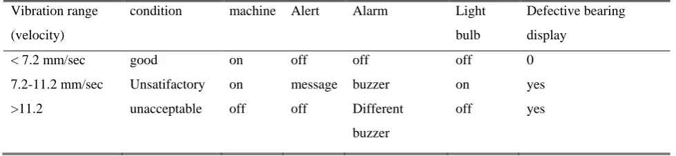
[image:2.595.317.531.277.476.2]The first step in a fuzzy inference system is the fuzzification of crisp inputs. It transforms the exact logic problem into a fuzzy logic problem. Unlike crisp logic, fuzzy logic deals with linguistic variables instead of numerical variables. The process of converting numerical variables of the problem into grades of membership for linguistic terms of fuzzy sets is called fuzzification. Thus it is a mapping from a certain input space to fuzzy sets in certain input universes of discourse.
Fig. 1: Operation of fuzzy systems
2: STEP 2: RULE EVALUATION
The next step in the fuzzy inference system is to apply the fuzzified inputs to the antecedents of the fuzzy rules. In case a given fuzzy rule has more than one antecedent, we make use of the fuzzy operator AND or OR in order to obtain a single truth value that would represents the result of the antecedent evaluation.
To evaluate the conjunction (intersection) & disjunction (union) of the rule antecedents, the fuzzy operators AND & OR are used respectively.
AND: μA∩B(x) = min [μA(x), μB(x)] OR: μA∪B(x) = max [μA(x),μB(x)]
Then the result of the evaluation would be applied to the consequent membership function. There are two main methods of doing so:
1. Clipping:
This involves cutting (alpha-cut) the consequent membership function at the level of result of the antecedent evaluation. As the top of the membership function is sliced, some information loss is inevitable in case of clipping. Still it is often preferred as it doesn„t involve too complex mathematics.
2. Scaling:
degrees by the truth value of the rule antecedent. There is not much loss of information.
3: STEP 3: AGGREGATION OF THE RULE OUTPUT This is the process of uniting the outputs of all rules that are invoked for a particular set of inputs into a single fuzzy set. The clipped or scaled consequent membership functions serve as the input to the aggregation process and the output of the process is one fuzzy set for each output variable. 4: STEP 4: DEFUZZIFICATION
It is the final step in the fuzzy inference process. It is the reverse process of Fuzzification. The Fuzzy Logic Controller (FLC) produces required output in a fuzzy set; however the final output has to be a crisp value. Defuzzification involves taking the aggregate output fuzzy set and producing a single crisp value corresponding to each of the output variables. Of various defuzzification methods, the centroid defuzzification method is most commonly used. Centroid defuzzification method involves finding a point that would represent the Centre of gravity of the aggregate fuzzy set. Mathematically this point can be expressed as:
5: IMPORTING AND EXPORTING FROM THE GUI TOOLS
When you save a fuzzy system to a file, you are saving an ASCII text FIS file representation of that system with the file suffix .fis. This text file can be edited and modified and is simple to understand. When you save your fuzzy system to the MATLAB workspace, you are creating a variable (whose name you choose) that acts as a MATLAB structure for the FIS system. FIS files and FIS structures represent the same system.
C: ANALYSIS OF FUZZY LOGIC TECHNIQUE
Fuzzy logic is a machine intelligent technique which can possibly be implemented in optimizing the CBM process. FL offers several unique features that make it a particularly good choice for many control problems including among other features the following:
1) It is inherently robust since it does not require precise, noise-free inputs and can be programmed to fail safely if a feedback sensor quits or is destroyed. The output control is a smooth control function despite a wide range of input variations.
2) Since the FL controller processes user-defined rules governing the target control system, it can be modified and tweaked easily to improve or drastically alter system performance. New sensors can easily be incorporated into the system simply by generating appropriate governing rules.
3) FL is not limited to a few feedback inputs and one or two control outputs, nor is it necessary to measure or compute rate-of-change parameters in order for it to be implemented. Any sensor data that provides some indication of a system's actions and reactions is sufficient. This allows the sensorsto be inexpensive and imprecise thus keeping the overall system cost and complexity low.
4) Because of the rule-based operation, any reasonable number of inputs can be processed (1-8 or more) and numerous outputs (1-4 or more) generated, although defining the rule base quicklybecomes complex if too many inputs and outputs are chosen for a single implementation
since rules defining their interrelations must also be defined. It would be better to break the control system into smaller chunks and use several smaller FL controllers distributed on the system, each with more limited responsibilities.
5) FL can control nonlinear systems that would be difficult or impossible to model mathematically. This opens doors for control systems that would normally be deemed unfeasible for automation.
Vibration analysis in rotating machinery is composed of the following parameters of concern velocity, displacement, acceleration, frequency and phase. Displacement, velocity & acceleration show level of oscillation present in the machine, the units are micron, mm/sec & mm/sec2 resp. Frequency computationally determined, signifies the causes of vibration / oscillation. Phase is useful in identifying the source of the vibration. The researchers used velocity as input parameter in this paper. Say something happens to the bearing then problem occurs in any of the bearings then the vibration of entire system increases and the magnitude of vibration is prominent in the problematic position of bearing.
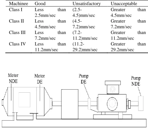
If the velocity range is „unacceptable‟ range then it automatically stops the system by tripping the relay creating a buzzer sound and it also gives an alert message with a different buzzer sound when magnitude of velocity is in „unsatisfactory‟ range. It is applicable in online condition monitoring system. In „unacceptable‟ and „unsatisfactory‟ condition it displays serial no. of defective bearing. Raw vibration data is necessary from a faulty machine to verify this model. The data is collected from a motor and a centrifugal pump using vibration meter for the analysis as shown in table 1 and Fig 2.
TABLE I: VIBRATION RANGES OF MACHINERY
Machinee Good Unsatisfactory Unacceptable Class I Less than
2.5mm/sec
(2.5-4.5)mm/sec
Greater than 4.5mm/sec Class II Less than
4.5mm/sec
(4.5-7.2)mm/sec
Greater than 7.2mm/sec Class III Less than
7.2mm/sec
(7.2-11.2)mm/sec
Greater than 11.2mm/sec Class IV Less than
11.2mm/sec
(11.2-29.2)mm/sec
[image:3.595.308.552.470.684.2]Greater than 29.2mm/sec
Fig. 2. Rotating system (Drawn by Auto CAD)
IV. MONITORINGSYSTEMSMODEL
GENERATION
problem is occurred in any position then the vibration of entire system increases. The magnitude of vibration is maximum in that bearing position where the problem is occurred. If the vibration is in „unacceptable‟ range (> 11.2 mm/sec) which is denoted by binary 1 below.
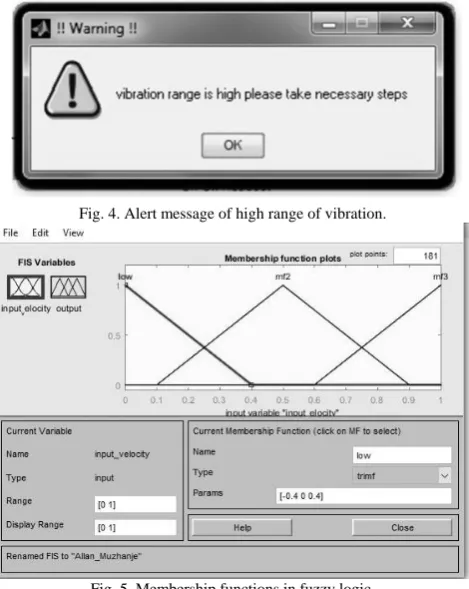
It stops the system by tripping the relay creating different buzzer sound and zero value is displayed in the display box. If the value is less than 11.2 then the data goes to second block for condition checking. If vibration is in „unsatisfactory‟ range then a message is displayed in the computer screen with a computerised buzzer sound to alert everybody otherwise the system is on. The alert message is shown in Fig-8. In „unsatisfactory‟ and „unacceptable‟ condition it displays the serial no. of defective bearing to find out the problematic source. A „Sound Generator‟ is used to create the sound. A „light bulb‟ is used to indicate that the vibration range is high.
If max (velocity) lies between 0 to 1.0mm/sec or 11.2mm/sec
alarm: ON : bulb ON alert :message
else alarm: Off : bulb Off alert : no message end
Source coding data:
// we tracked with a key called “source”, // if the target value comes with one
// u1, u2, u3 and u4 are four velocity ranges. source = max([u1, u2, u3, u4]);
if u1<7.2 && u2<7.2 && u3<7.2 && u4<7.2 source = 0;
// when velocity ranges from all machines will less than 7.2
else if u1>u2 && u1>u3 && u1>u4 source = 1;
// when velocity range of u1 is greater than all rest else if u2>u1 && u2>u3 && u2>u4
source = 2;
// when velocity range of u2 is greater than all rest else if u3>u1 && u3>u2 && u3>u4
source = 3;
// when velocity range of u3 is greater than all rest else source = 4 ;
// when velocity range of u4 is greater than all rest end( 4 times)
V.CONCLUSION
The model is useful for all classes of machines in online condition monitoring system. The vibration data used above was approximate of a class three machine. It predicts problems and protects machine from permanent breakdown. It also identifies and displays the problematic location in the machine without any human intervention. Excessive vibration can damage the machine components therefore this system will increase the machine lifetime.
ACKNOWLEDGMENT
I would like to thank my supervisor Professor Mbohwa for support and supervision. University of Johannesburg paid
[image:4.595.310.543.78.251.2]me all my trip and accommodation expenses and also registration.
Fig. 3. Matlab representation of unwanted range of speed.
[image:4.595.310.545.275.570.2]Fig. 4. Alert message of high range of vibration.
[image:4.595.308.547.533.755.2]Fig. 5. Membership functions in fuzzy logic.
REFERENCES
[1] Arunava Kabiraj Thakur, J. T. P. K. D., 2013. Modelling a condition monitoring based control using Matlab / Simulink for rotating electrical machines. International Journal of Recent advances in Mechanical Engineering (IJMECH), February.Vol.2(1).
[2] Ian, H., 2009. VIBRATION SIGNAL PROCESSING USING MATLAB. Acoustics Australia, 23(1), pp. 9-13.
[3] Rainer, K., 2014. Introduction to Gas Turbines and Applications. [Online] Available at: www.solarturbines.com [Accessed 02 November 2015].
[4] Randall, R. B., 2011. Vibration-Based Condition Monitoring. 1st ed. South Wales, Australia: John Wiley and Sons. [5] Richard, J., 1985. Wheeled Excavator Having a Dozer Blade
and a Boom-mounted Stabilizer wheel.. United States of America, Patent No. 4,501,334.
[6] Samhouri M, A.-G. A. A. A. S. H. I. M. W., 2009. An Intelligent Machine Condition Monitoring System Using. Jordan Journal of Mechanical Engineering, 3(4), pp. 294-305.
[7] Science, A. S. f., 2013. Principles of Halcyonics Active Vibration Isolation Technology, New York: Allyn and Sons. Shahsiah, A., 2009. Condition Monitoring of Power Transformers using Dissolved Gas Analysis, Detroit: Eponent Failure Analysis Associates.
[8] Zadeh. (2008, February 8). Is there a need for fuzzy logic? (Elsevier, Ed.) Information Sciences, 178, 2751-2779. [9] Zadeh. (2012, February 1). Fuzzy logic. Retrieved February
4, 2015, from Fuzzy logic:
http://www.scholarpedia.org/article/Fuzzy_logic
[10] Zahra. (2014, February 6). Electronics & Control Projects. Retrieved March 10, 2015, from Fuzzy Logic Control Tutorial:
https://sites.google.com/site/controlandelectronics/fuzzy-logic-control-tutorial
[image:5.595.75.565.505.618.2][11] Zhao Z and Chen C. (2001). Concrete bridge deterioration diagnosis using fuzzy inference system. Advances in Engineering Software , 317-325.
TABLE II: RESULTS DEDUCED AFTER MATLAB ANALYSIS
Vibration range
(velocity)
condition machine Alert Alarm Light
bulb
Defective bearing
display
< 7.2 mm/sec good on off off off 0
7.2-11.2 mm/sec Unsatifactory on message buzzer on yes
>11.2 unacceptable off off Different
buzzer