ISSN: 2231-5381
http://www.ijettjournal.org
Page 186
PLC and Fuzzy Logic Control of a Variable
Frequency Drive
Rinchen Geongmit DorjeeSenior Lecturer, Advanced Technical Training Centre, Bardang, Singtam, Sikkim, India
Abstract—This work deals with the control of a VFD which acts
as an intermediary between a three-phase induction motor and the PLC. The induction motor drives a conveyor belt which has three proximity sensor inputs. The first sensor gives the signal for motor to move in the forward direction, the second sensor halts the conveyor for a pre-defined period of time and the third sensor gives the signal for motor to move in the reverse direction. The PLC takes these inputs from the sensors and takes an appropriate action based on the logic developed for the motor control. Finally, the PLC output then becomes the VFD input, which after being reprocessed within the drive brings about the necessary control of the motor with respect to speed and position. In addition, Fuzzy Logic has also been applied to the system so that it can be trained to predict a reasonable output for even those inputs which were not foreseen by the network, therefore making the system flexible and easy to predict the result for various operating conditions.
Keywords—VFD, PLC, RS-Logix, Ladder Logic Programming, Fuzzy Logic Controller.
I. INTRODUCTION
A. Variable Frequency Drive
A VFD is a device used in a drive system consisting of three main sub systems: induction motor, main drive controller assembly and drive operator interface. They are used for applications which are run at different speeds due to surrounding circumstances. The revolutions per minute (rpm) of the driven shaft need to be increased or decreased depending on load changes, application requirements or other circumstances.
B. Programmable Logic Controller (PLC)
With the advent of technology and availability of motion control of electric drives, the application of Programmable Logic Controllers with power electronics in electrical machines has been introduced in the manufacturing automation systems. The use of PLC in automation processes increases reliability and flexibility and also reduces production costs. To obtain accurate industrial electric drive systems, it is necessary to use PLC interfaced with power converters, personal computers and other electric equipment. A PLC based control system was set up comprising of an Allen-Bradley PLC, an Allen-Bradley PowerFlex 4M Variable Frequency Drive, a three-phase induction motor and workstation ) has been delivered, configured and integrated
together for the monitoring and control of a motor driving a conveyor load.
Various control schemes have been used to operate the induction motor in speed and position control modes of operation using PLC programming developed on the workstation.
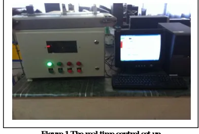
Figure 1 shows the real time control set up which was configured and tested for the experiment.
Figure 1 The real time control set up
II. LITERATURE REVIEW
Maria G. Ioannides et al. [1] described a PLC based monitoring and control scheme for a three-phase induction motor. A control program was developed, in accordance of which PLC continuously monitored the inputs and activated the outputs accordingly. A speed sensor was employed for speed feedback, a current sensor for load current feedback and an additional current sensor was attached to stator circuits. This paper suggested that PLC can be used in automation industries involving control of induction motor. The speed control of motor achieved through PLC gave the system high accuracy in speed regulation at constant speed-variable load operation. The efficiency of the induction motor system fed by an inverter was increased appreciably by using PLC. At high speeds and loads, the efficiency of PLC-controlled system is increased up to 10– 12%.
ISSN: 2231-5381
http://www.ijettjournal.org
Page 187
of voltages, currents, temperatures and speed were achievedand transferred to the computer for final protection design.
M Zajmovic et al. [7] presented a paper on the management of induction motors using PLC. The PLC, on the basis of the programmed logic sends control signals to the Variable Speed Drive (VSD), from which it receives feedback information on the state of the VSD and motor speed, so that the VSD can control the electrical motor with appropriate modulation of voltage and frequency. A Zelio PLC was used with the help of a frequency transformer which controlled a 5.5 kW asynchronous induction motor at a speed of 1500 rpm. A windows XP operating system with SCADA software from DAQFactory was used for interfacing to the induction motor through an Ethernet connection.
Y Birbir et al. [4] presented a paper on the design and implementation of a monitoring and control system for a three-phase induction motor based on Programmable Logic Controller technology. The PLC correlated the operational parameters to the speed requested by the user and monitored the system during normal and trip conditions. Tests of the induction motor system driven by the inverter and controlled by PLC provided higher accuracy in speed regulation as compared to a conventional V/f control system. The efficiency of PLC control is increased at high speeds up to 95% of the synchronous speed. This PLC proved to be a versatile and effective tool in industrial control of electric drives.
S. Da'na [6] discussed the design and implementation of a platform to remotely monitor and control PLC-based processes over TCP/IP or by using the GSM network. The platform is built using industry-standard off-the-shelf PLCs. Integrated with each PLC are communication processors that can be used for connectivity to the network and to a GSM modem.
P Sun et al. [8] presented the variable frequency principle and constant pressure principle on a water control system using PLC. By implementing variable frequency control to adjust the speed of the AC motor, not only its speed can be varied continuously but also the relationship between voltage and frequency is adjusted based on various load characteristics so that the motor is always running efficiently.
B Shuman [10] presented a paper on building a reliable Variable Frequency Drive system which regulates the speed of a three-phase electric AC motor by controlling the frequency and voltage of the power it delivers to the motor. VFD applications range from motion control applications to ventilation systems, from wastewater processing facilities to machining areas in various industries. Among many benefits, VFD offers the ability to save a substantial amount of energy during motor operation, they can maintain torque at levels to match the needs of the load, improve process control, reduce mechanical stress on three-phase induction motors by providing a “soft start,” and improve an electrical system’s power factor.
J Rasanen et al. [15] presented a paper on energy efficient solutions using Variable Frequency Drives to save energy and reduce emissions in new-builds and existing ships. Energy efficiency plays an important role in CO2 emission reductions which account up to 53% of total CO2 emission reductions. Using VFD in pump and fan applications onboard vessels, energy consumption can be reduced by as much as 60%
M. A. Badran et al [16] wrote a paper regarding fuzzy logic based speed control of a three phase induction motor in which conventional methods, while showing good results yet requires fine tuning to obtain optimum results. They have therefore used recent methods such as fuzzy logic controller to improve the performance of induction motor drives for monitoring operating conditions such as disturbance in load and changes in reference speed.
M. A. Mannan et al [17] presented a paper on fuzzy logic based speed control of induction motor which took into consideration core loss into account in which tthe flux and torque decoupling strategy was decoupled with respect to magnetizing current to reduce the effect of core loss. With the help of computer simulation, the entire performance of the system has been verified.
III.EXPERIMENTS CONDUCTED
A) Experimental Setup
1. The Allen-Bradley PowerFlex 4M AC drive is the smallest and most cost effective drive which provides powerful motor speed control in a compact, space saving design. It provides the application versatility to meet the demands such as space savings, application flexibility, feed-through wiring and ease-of-programming.
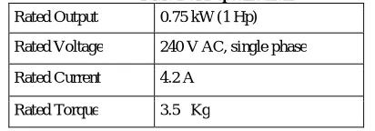
Table 1 shows the VFD specifications used in the experiment. Table 1 VFD specifications
Rated Output 0.75 kW (1 Hp)
Rated Voltage 240 V AC, single phase
Rated Current 4.2 A
Rated Torque 3.5 Kg
2. The PLC used in this project was Allen Bradley MicroLogix 1400 series. The basic parts of a 1400 series PLC are Power Supply, CPU, Discrete Input Module and Discrete Output Module.
Table 2 shows the PLC specifications used in the experiment.
Table 2 PLC specifications Sl Description Details
1 Dimensions HxWxD
ISSN: 2231-5381
http://www.ijettjournal.org
Page 188
2 Weight 0.9 kg3 Number of I/O 24 inputs (20 digital 4 analog) and 14 outputs (12 digital 2 analog)
4 Power supply voltage
24V DC
5 Power supply inrush Current
24V DC:
15 A for 20 ms 6 Power consumption 50W
3. Input Variables taken:
Three proximity sensors on conveyor belt
Frequency input of VFD to control output speed 4. Output response – speed and position of three-phase
induction motor driving a conveyor belt load.
B) Experimental Setup
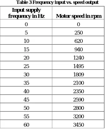
For the present work a real time control set up comprising of Allen-Bradley PLC, an Allen-Bradley PowerFlex 4M Variable Frequency Drive, a three-phase induction motor driving a conveyor belt load controlled by ladder logic software installed in a personal computer. For various values of input supply frequencies, the corresponding values of motor speed in rpm were obtained as shown in Table 3.
Table 3 Frequency input vs. speed output
Input supply
frequency in Hz Motor speed in rpm
0 0
5 250
10 620
15 940
20 1240
25 1495
30 1809
35 2100
40 2350
45 2590
50 2800
55 3200
60 3450
IV.OBJECTIVES AND OVERVIEW OF THE PROPOSED MECHANISM
A) Objectives
Induction Machines, the most widely used motor in industry, have been traditionally used in open-loop control applications, for reasons of cost, size, reliability, ruggedness, simplicity, efficiency, less maintenance, ease of manufacture and its ability to operate in dirty or explosive conditions. With developments in Micro-processors/DSPs, power electronics
and control theory, the induction machine can now be used in high performance variable-speed applications.
Synchronous speed or rather, motor speed can be controlled by varying supply frequency. Voltage induced in stator is directly proportional to product of supply frequency and air-gap flux. If stator drop is neglected, terminal voltage can be considered proportional to product of frequency and flux. V1α
f.Φ
B) Overview of the proposed mechanism
When a certain application does not require a constant speed at all times, VFD provides a flexible approach as compared to traditional methods of speed control. For instance, a pump delivering fluid supply for cooling purpose may require peak load operation only for a short period of application. For the remaining hours of operation, fluid supply requirement may require only a fraction of the peak load supply therefore, enabling the pump to run at lower speed than usually will create energy saving benefits.
The hardware system comprises of a PLC which has been connected to control and monitor a VFD which acts like an intermediary between the three-phase induction motor and the PLC. The induction motor drives a conveyor belt which has three proximity sensor inputs. . The first sensor gives the signal for motor to move in the forward direction, the second sensor halts the conveyor for a pre-defined period of time and the third sensor gives the signal for motor to move in the reverse direction.
The PLC takes these inputs from the sensors and takes an appropriate action based on the logic developed for the motor control. Finally, the PLC output then becomes the VFD input, which after being reprocessed within the drive brings about the necessary control of the motor with respect to speed and position.
The programming of the PLC was done in RS-Logix which is a ladder logic type of programming with which the instructions to the VFD and induction motor are processed and vice versa.
C) Fuzzy Logic Controller
Fuzzy logic basically trains the system on a series of “If-Then” rules in which for a various possible combination of inputs, there is a predicted output such that at the end, even for an unknown input, the fuzzy logic controller can predict a certain output. The “It-Then” rules tag each input variable into Membership Functions in such a way that every membership function is not a crisp set but overlap each other. There are three main parts of the fuzzy inference system as shown in Figure 2
ISSN: 2231-5381
http://www.ijettjournal.org
Page 189
i) FuzzificationFuzzification is the process of converting crisp sets into overlapping Membership Functions which are also known as fuzzy sets
ii) Fuzzy Inference System
Here, the input fuzzy sets are correlated to output fuzzy sets with the help of “If-Then” rules so as to achieve appropriate outputs. This is called is known fuzzy inference system. The Mamdani fuzzy inference system is the most common method which has the advantage of intuition, acceptance and suitability to human input. The Mamdani fuzzy inference system is shown in Figure 3
Figure 3 Typical rules of fuzzy logic
iii) Defuzzification
The final step in the process is defuzzification in which a crisp output is derived from a fuzzy set through fuzzy inference with the help of mthods such as centroid, average of maxima, midpoint of maxima, median, area, height, etc. The most commonly used method out of all these is the centroid defuzzification.
V. RESULTSANDDISCUSSION
A. Ladder Logic Programming
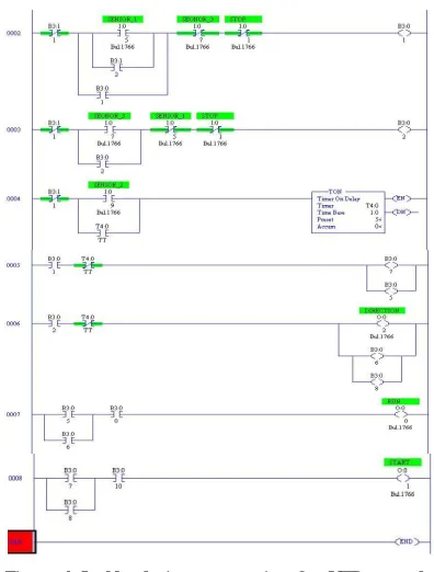
The experiments were conducted based on ladder logic programming which is a software installed on a personal computer according to which the PLC takes the sensor inputs, processes them according to the program and gives the output to the VFD which again processes this input within the drive and finally controls the speed and position of the motor. The ladder logic programming is shown in Figure 4.
Figure 4 Ladder logic programming for VFD control of induction motor
B. Fuzzy Logic Toolbox design
The first step in this method was to create a Fuzzy Logic Toolbox design using the specified values of inputs and outputs. This toolbox design is shown in Figure 5
Figure 5 Fuzzy Logic Toolbox design.
C. Fuzzy Logic Membership Function
The design of a Fuzzy Logic Controller is made in such a way that the Membership Functions should overlap each other in order to sustain a fuzzy set of rules as shown in Figure 6
ISSN: 2231-5381
http://www.ijettjournal.org
Page 190
D. Fuzzy Logic Rules
With the reference to the experimental data collected from the laboratory, fuzzy logic ”If-Then” rules have to be established for each reading so that the system is trained to predict a reasonable output for even unknown input variables. The fuzzy logic rule editor has been shown in Figure 7
Figure 7 Fuzzy Logic Rules
E. Fuzzy Logic Rule Viewer
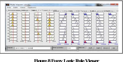
With the reference to the experimental data collected from the laboratory, the fuzzy logic rule viewer gives a comprehensive sighting between various input and output variables. By changing any one input, the prediction of the values for the rest of the outputs is changed accordingly. The rule viewer is shown in Figure 8
Figure 8 Fuzzy Logic Rule Viewer
VI.CONCLUSION
The present work was motivated to develop a scheme to monitor and control a Variable Frequency Drive using PLC. A thorough study of all the hardware components was done including their specifications, functioning and overall performance. Software platform namely AllenBradley ladder logic programming RS Linx was comprehended, analysed and implemented.
A 0.75 KW three-phase induction motor was fully automated using a Variable Frequency Drive and PLC. The drive used in this set-up offered various control modes of motor operation. The configuration and settings to run the motor in two control modes viz., speed and position were done systematically A ladder logic program was developed and verified in RS Linx software which enabled the motor to obtain two different positions in succession with a specified time interval between
the positions. A complete study and practical hands on the PLC and the drive operation have imparted a fairly good idea about the industrial automation systems.
REFERENCES
[1] Marwan A. Badran, Mostafa A. Hamood, Waleed F Faris, Fuzzy Logic Based Speed Control System for Three-Phase Induction Motor. “Eftimie Murgu” Resita, Anul XX, NR, 1,2013, ISSN 1453-7397
[2] Mendel J.M., “ F u z z y L o g i c S y s t e m s f o r E n g i n e e r i n g : A t u t o r i a l , ” Proceedings of the IEEE, Vol. 83, pp. 345-377, 1995. [3] Javadi S., “ I n d u c t i o n M o t o r D r i v e U s i n g F u z z y L o g i c ”
International Conference on Systems Theory and Scientific Computation, Athens, Greece, 24-26, 2007
[4] Emad Abdelkarim, Mahrous Ahmed, Mohamed Orabi, Peter Mutschler, “Fuzzy Logic Speed Controller of a 3-Phase Induction Motor for Efficiency Improvement” JPE 12-2-9, http://dx.doi.org/10.6113 /JPE.2012.12.2.305
[5] A. M. Eltamaly, A. I. Alolah, and B. M. Badr, “Fuzzy controller for three phases induction motor drives,” IEEE Autonomous and Intelligent Systems (AIS) 2010, Vol. 1, pp. 1-6, Aug. 2010.
[6] K. R. Kumar, D. Sakthibala, and S. Palaniswami, “Efficiency optimization of induction motor drive using soft computing techniques,” International Journal of Computer Application, Vol. 3, No. 1, Jun. 2010. [7] C. Thanga Raj, “Energy Efficient Control of Three-Phase Induction Motor – A Review”, International Journal of Computer and Electrical Engineering, Vol 1, No 1, April 2009, 1793-8198
[8] B. K.Bose, Modern Power Electronics And Ac Drives, Printed Hall PTR 2002.
[9] P Tripura, Y Srinivasa Kishore Babu, “Fuzzy Logic Speed Control of Three Phase Induction Drive”, World Academy of Science, Engineering and Technology, Vol 5, 2011-12-20
[10] Ravi Maloth, “Speed Control of Induction Motor Using Fuzzy Logic Controller”, National Conference on Electrical Sciences -2012 (NCES-12) ISBN: 978-93-81583-72-2
[11] Bao-Gang Hu, George K. I. Mann, “A systematic study of fuzzy Pid controllers- Function based evaluation approach”.IEEE Transactions on Fuzzy Systems, vol.9, no. 5, October 2001.
[12] Kamini Devi, Shailendra Gautam, Deepak Nagaria, “Speed control of a 3-phase induction motor using self-tuning fuzzy PID controller and conventional PID controller”, International Journal of Information & Computation Technology, ISSN 0974-2239 Volume 4, Number 12 (2014), pp. 1185-1193
[13] Mohd Shahrieel Mohd Aras, Eric Chee Sai Hoo, Mohd Hendra bin Hairi, Syed Najib Bin Syed Salim, Intan Azmira binti Wan Abd Razak, “Comparison of Fuzzy Control Rules using MATLAB Toolbox and Simulink for DC Induction Motor-Speed Control”, 2009 International Conference of Soft Computing and Pattern Recognition.
[14] S. Rajasekaran, G.A. Vijaylakshmi Pai”Neural Networks, fuzzy logic, and genetic algorithms synthesis and applications”, Prentice Hall India, Eastern Economy Edition,(2005)
[15] Mohammad Abdul Mannan, Asif Islam, Mohammad Nasir Uddin, Mohammad Kamrul Hassan, Toshiaki Murata, Junji Tamura, “Fuzzy logic based Speed Control of Induction Motor considering core loss into account”, Intelligent Control and Automation, 2012, 3, 229-235, http://dx.doi.org/10.4236/ica.2012.33026
[16] Marwan A. Badran, Mostafa A. Hamood, Waleed F Faris, Fuzzy Logic Based Speed Control System for Three-Phase Induction Motor. “Eftimie Murgu” Resita, Anul XX, NR, 1,2013, ISSN 1453-7397
[17] Mohammad Abdul Mannan, Asif Islam, Mohammad Nasir Uddin, Mohammad Kamrul Hassan, Toshiaki Murata, Junji Tamura, “Fuzzy logic based Speed Control of Induction Motor considering core loss into account”, Intelligent Control and Automation, 2012, 3, 229-235, http://dx.doi.org/10.4236/ica.2012.33026