DESINGING OF ANN BASED SPEED
CONTROLLER
FOR PHASE CONTROLLED DC
MOTOR
MR. M.V.SUDARSAN
Vignan’s LARA Institute of Technology and Sciences, Department of EEE Vadlamudi, Guntur district, Andhra Pradesh, India
DR. G.R.K. MURTHY
Prof. School of Electrical Engineering, Vignan University Vadlamudi, Guntur district, Andhra Pradesh, India
MR. G.R.S. NAGA KUMAR
Vignan’s LARA Institute of Technology and Sciences, Department of EEE Vadlamudi, Guntur district, Andhra Pradesh, India
Abstract:
For electrical drives good dynamic performance is mandatory so as to respond to the changes in command speed and torques, so various speed control techniques are being used for real time applications. The speed of a dc motor can be controlled using various controllers like PI- Controller, Artificial Neural Network (ANN) controller. ANN theory is recently getting increasing emphasis in process control applications. The paper describes application of ANN in a speed control system that uses a phase-controlled bridge converter and a separately excited DC machine. The ANN controller for current and speed loops are implemented in MATLAB/SIMULINK, replacing the conventional Proportional-Integral (PI) control method. The simulation study indicates the superiority of artificial neural network control over the conventional control methods. This control seems to have a lot of promise in the applications of power electronics.
Keywords: D.C. motor, PI - Controller, Artificial Neural Network (ANN) - Controller.
I.INTRODUCTION
Speed control is required in large number of industrial and domestic applications like transportation systems, rolling mills, paper mills, textile mills, machine tools, fans, pumps, robots, washing machines etc. Systems employed for motion control are called drives and Drives employing electric motors are known as electrical drives. Induction and synchronous motors were mainly used in fixed speed applications. Variable speed applications were dominated by dc motors. Because of their simplicity, ease of application, reliability and favourable cost have long been a backbone of industrial applications. The speed can be controlled by varying the applied voltage to the armature or by varying the field current. The speed control below the base speed is achieved by variation of the applied voltage where as the variation of field current (field weakening) provides speed control above the base speed [1].
proportional derivation integral (PID), adaptive, Fuzzy logic controller (FLCs), and Artificial neural network (ANN) have been developed for speed control of dc motors.
Major problems in applying a conventional control algorithm in a speed controller are the effects of non-linearity in a DC motor. The non-linear characteristics of a DC motor such as saturation and friction could degrade the performance of conventional controllers. Many advance model-based control methods such as variable-structure control and model reference adoptive control have been developed to reduce these effects. However, the performance of these methods depends on the accuracy of system models and parameters. Generally, an accurate non-linear model of an actual DC motor is difficult to find, and parameter values obtained from system identification may be only approximate values.
Emerging intelligent techniques have been developed and extensively used to improve or to replace conventional control technique because these techniques do not require a precise model. One of intelligent technique, artificial neural network is used to replace conventional controller. These can accommodate many inputs in parallel and encode the information in a distributed fashion and can improve the performance of a D.C. Motor [3] [4] [5].
This present work is to “Analyse the performance of speed control of DC motor using PI and ANN controllers”. The emphasis has been given on two quadrant operation. With the help of transfer function models, analysis of the performance of the dc motor drives for different cases has been done. Broadly, two control strategies with ANN are proposed for separately excited D.C. motor, current control and speed control strategy.
2.THREEPHASECONVERTERCONTROLLEDDCMOTORDRIVES
Direct current machines have been in service for more than a century. Their fortune has changed a great deal since the introduction of the induction motor. DC motors have staged a comeback with the advent of silicon-controlled rectifier used for power conversion facilitating a wide range speed control of these motors
The control schematic of a fully controlled bride converter fed separately excited dc motor is shown in the fig.1.The thyristor bridge converter gets its ac supply through a three phase transformer and fast acting ac contactors. The DC motor has a tacho-generator whose output is utilized for closing the speed loops. The motor is driving a load considered to be frictional for this treatment. The speed command and ωr*is compared to the
speed signal to produced a speed error signal. This signal is processed through a proportional plus integrator (PI) controlled to determine the torque command. The torque command is limited, to keep it within the safe current limits. The armature current command ia* is compared to the actual armature current ia to have a zero current
error. In case, there is an error, a PI current controller processes it to alter the control signal Vc. The control
signal accordingly modifies the triggering angle α to be sent to the converter for implementation [2].
Fig.1 Schematic Diagram for Speed control of converter fed DC motor.
A Dynamic model of the machine subjected to control must be known in order to understand and design controllers for the drives. Due to the fact that every good control has to face any possible changes of the plant, it could be said that the dynamic model of the machine could be just a good approximation of the real plant. Nevertheless, the model should incorporate all the important dynamic effects occurring during both steady state and transient operations.
3.MATHEMATICALMODELIINGOFCONVERTERFEDDCMOTOR.
The load is assumed to be proportional to speed and is given as: Tl = Bl ωm. To decouple the inner current loop
from machine inherent emf loop, it is necessary to split the transfer function between speed and voltage into two cascade transfer functions, first between speed and armature current and then between armature current and input voltage. Therefore the transfer function model of DC machine, the transfer function model of 3-phase fully controlled bridge converter is required and has been reported in literature [7].
A SIMULINK model has been developed to test the performance of the ANN controller approach and conventional PI controller mode on DC motor drive. The specifications of the DC motor drive to be controlled and converter are given in Appendix I. The maximum current permitted in the motor is 20 A. Transfer functions of all subsystems of given plant model are taken as per [6].
Transfer function of motor is given in equation 1.
1 s0.1077
1 s0.0208
s0.7 1 30 2 sT 1 1 sT 1 m sT 1 1 K s a V s a I (1)
Transfer function of load is given in equation 2.
0.7s 1 14.5 0.7s 1 0.0869 1.26 m sT 1 t B b K s a I s m W (2)Here Tm=JBtand Bt=B1+BL
Transfer function of the three phase fully controlled bridge converter is given in equation 3.
( ) ( )
( ) 1+0.00138s
05 . 31 = sT + 1 K = s V s V = s G r r c a
r (3)
Where K1, Kr, are the gain of motor and converter. Tm and Tr are the time constant for motor, and converter.
4.CLOSEDLOOPSPEEDCONTROLOFADCMOTOR
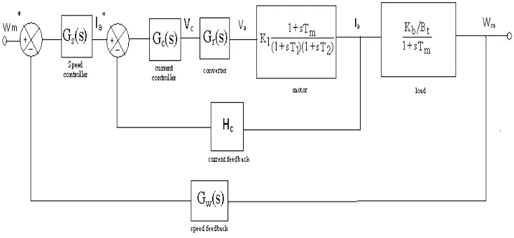
Fig.2 shows the block diagram representation of the closed loop operation of DC motor.
It employs an inner current control loop within an outer speed-loop. Inner current control loop is provided to limit the converter and motor current or motor torque below a safe limit. Inner current loop is also beneficial in reducing the effect on drive performance of any non-linearity present in converter-motor system.
4.1 PI CONTROL METHOD
For controlling the speed of DC motor, PI control strategy is applied with current controller and speed
controller. The transfer functions for PI current controller and PI speed controller are obtained from the Ziegler – Nicholas method [8], and are given in equations 4 and 5.
( )
(
)
(
)
s 0208 . 0 s 0208 . 0 + 1 33 . 2 = sT sT + 1 K = s G c c c c (4)( )
(
)
(
)
s 0188 . 0 s 0188 . 0 + 1 73 . 28 = sT sT + 1 K = s G s s s s (5)Where Kc and Ks are the proportional gain constants of current and speed controllers. Tc and Ts are the integral
time constants of current and speed controllers respectively.
4.2ARTIFICIALNEURALNETWOK(ANN)CONTROLLER
An ANN controller is a sophisticated intelligent controller. The designing of ANN controller requires four steps.
1. Obtaining the inputs and target samples from the reference plant. (Here the reference plant is considered as an PI controlled DC motor)
2.Extracting the network architecture consisting of a minimum of any hidden layer. 3.Training the network with the samples generated.
4.Simulating the network and obtaining the controller.
The architecture of the proposed neural network is a two layer feed forward neural network, consisting of a single hidden layer and an output layer. The hidden layer consists of ten neuron cells with tan sigmoid activation function and is shown in fig.3. The outer layer consists of one neuron cell with linear activation function [9].
iz {1 ,1 } 1 dotprod9 w p z dotprod8 w p z dotprod7 w p z dotprod6 w p z dotprod5 w p z dotprod4 w p z dotprod3 w p z dotprod2 w p z dotprod10 w p z dotprod1 w p z Mux Mux
IW {1 ,1 }(9 ,:)' weights IW {1 ,1 }(8 ,:)'
weights IW {1 ,1 }(7 ,:)'
weights IW {1 ,1 }(6 ,:)'
weights IW {1 ,1 }(5 ,:)'
weights IW {1 ,1 }(4 ,:)'
weights IW {1 ,1 }(3 ,:)'
weights IW {1 ,1 }(2 ,:)'
weights
IW {1 ,1 }(10 ,:)' weights IW {1 ,1 }(1 ,:)'
weights
pd {1 ,1 } 1
Table. 1 shows the network parameters of the proposed neural network controller.
The designing of any neural network involves the following six primary steps. 1.Create the network.
2.Configure the network.
3.Initialize the weights and biases. 4.Train the network.
5.Validate the network. 6.Use the network.
The training input samples and target outputs were generated from the PI controlled DC Motor. The least mean square error technique is used to update the weight vector [10].
5. RESULTS AND CONCLUSION
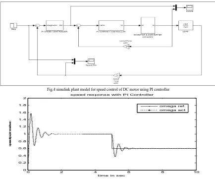
Simulink model for speed control of DC motor with PI controller is shown in fig.4
Fig.4 simulink plant model for speed control of DC motor using PI controller
0 2 4 6 8 10
0 0.2 0.4 0.6 0.8 1 1.2 1.4 1.6 1.8 2
time in sec
sp
e
e
d
(p
u
) i
n
ra
d
/s
e
c
speed response with PI Controller
omega ref. omega act
Fig .5 Speed response of PI controlled DC motor
S.No Description Required values
1 No: of hidden layers 01
2 No: of hidden neurons 10
3 Hidden neuron activation
function TANSIG
4 Output neuron activation
function PURELIN
Fig.5 shows the speed response of DC motor with the proposed speed and current controllers for a reference step speed from 1.0 pu to 0.6 pu. The settling time of the response is 1.8 sec, peak overshoot is 58% and zero steady state error.
Simulink model for speed control of DC motor with ANN controller is shown in fig.6
Fig.6 simulink plant model for speed control of DC motor using ANN controller.
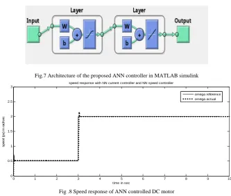
The architecture of the proposed ANN controller in MATLAB simulink is shown in fig.7
Fig.7 Architecture of the proposed ANN controller in MATLAB simulink
0 1 2 3 4 5 6 7 8 9 10
0 0.5 1 1.5 2 2.5 3
time in sec
s
peed
(
pu)
i
n
rad/
s
ec
speed response with NN current controller and NN speed controller
omega reference omega actual
Fig .8 Speed response of ANN controlled DC motor
0 1 2 3 4 5 6 7 8 9 10 0
0.5 1 1.5 2 2.5 3
tim e in s ec onds
s
pee
d(
pu
) i
n
r
ad
/s
ec
s peed res pons e of a DC m otor with nueral s peed and c urrent c ontroller
om ega referenc e om ega ac tual
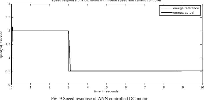
Fig .9 Speed response of ANN controlled DC motor
Fig.9 shows the speed response of DC motor with the proposed ANN speed and ANN current controllers for a reference step speed from 2.0 pu to 0.5 pu. The settling time of the response is 0.1 sec, peak overshoot is 5% and zero steady state error.
5.1COMPARISIONOFPIANDARTIFICIALNEURALNETWORK(ANN)CONTROLLERS
Table.2 comparison of PI and ANN controller.
6. CONCLUSION
By using ANN mode controller for the separately excited DC motor speed control, the following advantages have been realized.
The speed response for constant load torque shows the ability of the drive to instantaneously reject the perturbation. The design of controller is highly simplified by using a cascade structure for independent control of flux and torque. Excellent results added to the simplicity of the drive system, makes the ANN based control strategy suitable for a vast number of industrial, paper mills etc. The sharpness of the speed output with minimum overshoot defines the precision of the proposed drive. Settling time has been reduced to a label of 0.1 sec. Hence the simulation study indicates the superiority of artificial neural network control over the conventional control methods. This control seems to have a lot of promise in the applications of power electronics.
7. REFERENCES
[1] Ion Boldea, S.A. Nasar, Electric Drives, Taylor & Francis, CRC Press, 2006.
[2] B.K. Bose, “Expert system, fuzzy logic, and Neural Networks applications in Power Electronics and motion control,” Proc. of the IEEE, vol.82 pp.1303- 1323, Aug. 1994.
[3] K.S. Narendra and K. Parthasarathy, “ Identification and control of dynamical system using neural networks,” IEEE Trans., Neural Network, vol. 1. pp. 4-27, Mar. 1990.
[4] Phan Quoc Dzung and Le Minh Phuong, “ ANN- Control system dc motor,” IEEE Trans., Neural Network, 1998.
[5] S. weerasoory and M.A. AI-Sharkawi, “identification and control of d.c. motor using back propagation neural networks” IEEE transactions on energy conversion, vol. 6, No. 4 pp 669, Dec. 1991.
[6] J.Santana, J.L.. Naredo, F. Sandoval, I. Grout, and O.J. Argueta, “Simulation and construction of a speed control for a DC series motor,” mechatronics, vol. 12, issues 9-10, Nov.-Dec.2002,pp. 1145-1156
[7] P.C. Sen, Principle of Electric Machines and Power Electronics, John Wiley and Sons, !989. [8] Ajit K.Mandal, Introduction to control engineering,New age international publishers,pp.317 – 388. [9] S. Hykin, Neural Networks, Macmillan, NY, 1994.
[10] J.H. Mines, MATLAB Supplement to Fuzzy and Neural Approaches in engineering, John Wiley, NY, 1997. [11] S.G. German-Gankin-The computing modeling for power electronics system in MATLAB, 2001.
APPENDIX -I
The specifications of the DC motor and three phase fully controlled bridge rectifier are as follows
DC Motor specifications:
Power rating = 5HP,
D.C. motor input voltage = 220V, Armature current rating = 8.3A,
Rated speed = 1470 rpm,
Armature resistance Ra = 4 Ω,
Moment of inertia J = 0.0607kg-m2, Armature Inductance La = 0.072 H,
Friction coefficient Bt = 0.0869 N – m/rad/ sec,
Torque constant Kb = 1.26 V/rad/sec.
Converter specifications:
Supplied voltage = 230 V, 3 – Phase, A.C. Frequency = 50 Hz, Maximum control input voltage is ± 10 V. SPEED RESPONSE
Strategy of Control
Peak Overshoot in per unit
Settling Time in Sec.
Steady State Error in per
unit
PI Control
Method 0.58 1.8 ZERO
ANN Control