123
Cluster Head Zone Based LEACH Protocol For
Wireless Sensor Networks
Monika, Damanpreet SinghAbstract: Wireless Sensor Network (WSN) consists of immense number of sensor nodes are deployed in a specific region for intelligently monitoring of the hazardous environment where continuous human intervention is defenseless and infeasible. Sensor nodes are minor in size with limited processing capacity, storage, communication ability and battery life. Considering limited battery life, energy consumption of sensor nodes must be reduced to enlarge lifetime and performance of WSN by employing energy efficient routing protocol in WSN. In recent times numerous routing mechanisms have been proposed but LEACH still attracts the most consideration in research area as its architecture provides balanced energy consumption among nodes. But due to long distance communication, LEACH consumes more energy for data transmission and results in early death of WSN. In this paper, to augment the performance of LEACH protocol a new protocol namely Cluster Head Zone based LEACH (CHZ-LEACH), is proposed by redefining cluster head election method based on remaining energy, average energy and a region defined for cluster heads named as cluster head zone. CHZ-LEACH has been subjected to exhaustive simulation with NS-2 and the analyzation of results predicts the supremacy of CHZ-LEACH over LEACH.
Keywords: Cluster-based routing protocols, Cluster Head Zone, LEACH protocol, NS2, WSN.
————————————————————
1
I
NTRODUCTION With the advancements in the areas of wireless communication, mobile internet and embedded computing it is feasible to develop tiny and low-cost sensors which are responsible for sensing, gathering and processing the data. When immense numbers of sensor nodes are deployed in a specific area for achieving a common goal, the network called Wireless Sensor Network (WSN). Sensor nodes, with limited sensing, computing and wirelessly communicating capabilities, can connect with each other as well as with the base station using wireless radio [1]. WSN has vast applications in today’s world, such as military and environmental applications, helps to evade catastrophic infrastructure failure, sustain natural resources, checking water level and air pollution of an industry, monitoring widespread fire, increase productivity, upgrade security and many more [2]. WSN design is influenced by many parameters, such as energy consumption, deployment of nodes, scalability, fault tolerance, network lifetime, power consumption, etc. [3]. But Energy Efficiency and longer lifetime of network are the most vital constraints of designing a WSN. To minimize energy utilization and prolonging lifetime of network, various routing mechanisms have been proposed and classified based on network structure and protocol operation [4]. Depending upon network structure, routing schemes can be further grouped into Flat network routing, Hierarchical network routing and Location based routing [5]. In flat routing protocol, all sensor nodes typically play identical roles and functionalities. Scalability is the main issue with the flat network routing protocols as they are only feasible with small area networks. Hierarchical routing protocol, whole network is divided into clusters in which few nodes become cluster head (CH), these cluster head nodes process and send the data to base station (BS), rest of nodes collect data from environment and send it to cluster head nodes. In Location based protocols, the information of location coordinates of each senor node is captured with the support of Global Positioning System (GPS) and this position information is shared with the neighboring nodes for communication. Heinzelman et al. [6] proposed an energy efficient protocol named as Low Energy Adaptive Clustering Hierarchy (LEACH). In LEACH, nodes are organized into clusters124 communication capability and storing capacity, so methods of
improvement of energy efficiency of nodes and extending network lifetime is the motivation of current researches. There are various problems in existing variants of LEACH such as additional overhead of communication, problem of variability of cluster head, control message overhead and scalability problem and moreover LEACH is not appropriate for large network area. This study proposes improvement over LEACH protocol called Cluster Head Zone based LEACH (CHZ-LEACH), based on residual energy, average energy of the sensor nodes and cluster head zone. A circular area around base station is defined and named as Cluster head zone (CHZ-LEACH). If a node comes under cluster head zone and its residual energy is more than average energy, then node is eligible turn out as cluster head. Cluster formation depends on the minimum path distance from node to cluster heads. This consideration helps nodes to survive for long as it extends First Node Dies (FND), Half Node Dies (HND) and Last Node Dies (LND) [14]. The rest part of the paper is structured in the following manner: Section 2discusses the energy model, design, formulation and procedural components and explains the algorithms of the CHZ-LEACH. In section 3, environment and metrics of NS-2 simulation of CHZ-LEACH are defined and comparison with the LEACH protocol is presented. Finally, conclusion of this work is discussed in section 4.
2
C
LUSTERH
EADZ
ONE BASEDLEACH
P
ROTOCOL(CHZ-LEACH)
2.1 Radio Energy Dissipation model
Routing protocols of wireless sensor network have different simulation environment and energy models where every energy model has some pros and cons. In CHZ-LEACH, Dissipation model of radio energy [15] as shown in fig. (1) is considered. In this energy model, energy is consumed in running electronic circuitry and power amplification.
Fig. 1 Dissipation model of Radio energy
To transmit a message signal of bit b over a distance d, energy consumption is represented in (1).
𝐸 (𝑏, 𝑑) = 𝐸 (𝑏) + 𝐸 (𝑏, 𝑑) = 𝑏𝐸 + 𝑏𝜀 𝑑 (1)
Here, 𝐸 is energy consumed in running electronic circuitry
and β is constant depends on distance d. In (2), if d is less than threshold distance dt then free space channel model Ɛfsis used;
otherwise multipath fading channel model Ɛmf is used. = {𝑏 ∗ 𝐸 + 𝑏 ∗ 𝜀 𝑑 , 𝑑 < 𝑑
𝑏 ∗ 𝐸 + 𝑏 ∗ 𝜀 𝑑 , 𝑑 ≥ 𝑑} (2)
To receive this signal energy consumption will be as shown in (3).
𝐸 (𝑏) = 𝐸 (𝑏) = 𝑏𝐸 (3)
2.2 Proposed CHZ-LEACH
CHZ-LEACH protocol enhances the performance of LEACH protocol by distributing energy load among nodes uniformly. CHZ-LEACH operation is split into two phases: Setup phase in which formation of cluster takes place followed by steady phase where data transmission takes place. In CHZ-LEACH, three factors are used in process of cluster head selection; average energy, residual energy and distance from BS. A circular area is defined around base station in the network called cluster head zone so that distance of transmission should remain minimum between CH and BS. If a node comes under cluster head zone and its residual energy is more than average energy, then that node is eligible to be elected as cluster head. Cluster formation is depending upon the minimum path distance from node to cluster heads.
2.2.1 Network Assumption
In fig. (2), network of 100×100 m2 is shown in which 100 nodes
are deployed randomly. A circular region is defined inside the network and named as cluster head zone where boundaries of this zone are defined by distance from base station. Inner boundary 𝑑 and outer boundary 𝑑 of cluster head zone
are calculated based on the (4) and (5) respectively. A node can only participate in process of cluster head selection if it belongs to cluster head zone. In given fig. (2), nodes are represented with plus shape, the nodes which does not belong to cluster head zone are colored as red color and play the part of non-cluster head nodes for lifetime of the network. Similarly, nodes which belong to cluster head zone are of blue color and can act as cluster head as well as non-cluster head and black color is assigned for the representation of base station.
𝑑 = 𝑀 ∗ √2 6⁄ (4)
𝑑 = 𝑀 ∗ √2 3⁄ (5)
Fig. 2 100 randomly deployed nodes in network
125 2.2.2 Setup phase
Setup phase for first round is different from the rest of the rounds as in the first-round, there is no consumption of energy therefore, remaining energy is equal to its initial energy, so in first round cluster election is based on threshold and distance of node from base station only, there is no consideration of energy for the first-round. For the rest of the rounds, cluster head election process is based on all three factors; average energy, residual energy, and distance of node from base station belongs to cluster head zone (CHZ). Algorithm (1) defines the setup phase for all rounds, for first round Dist_thresh_0() is defined in algorithm (2), similarly for the rest of rounds Dist_thresh_all() is defined in algorithm (3).
Algorithm 1: Setup_phase()
for round = 0 to TR
if round == 0 call Dist_thresh_0(); end if
Else
call Dist_thresh_all(); end for
Algorithm (2) defines the setup phase for the initial first round, a node belongs to cluster head zone and random number generated is less than threshold [6] defined in (6). Algorithm (3) Dist_thresh_all() define the setup phase for the rest of the rounds. It differs from the algorithm (2) Dist_thresh_0() in cluster head selection process, where cluster head is elected if it belongs to CHZ, residual energy, threshold 𝑡ℎ𝑟𝑒𝑠ℎ.
𝑡ℎ𝑟𝑒𝑠ℎ(𝑖) = { ∗( ) 𝑖𝑓 𝑖 ∈ 𝑆
0 𝑜𝑡ℎ𝑒𝑟𝑤𝑖𝑠𝑒
} (6)
N and i are number of nodes and current node respectively, k are optimal clusters for current round r and S is set of nodes which are not cluster head in (r mod N/k) rounds.
Algorithm (3) Dist_thresh_all() define the setup phase for the rest of the rounds. It differs from the algorithm (2) Dist_thresh_0() in just cluster head selection process, where cluster head is elected based on residual energy, threshold and existence in cluster head zone.
Algorithm 3: Dist_thresh_all()
for node i = 1 to N
if (node i was cluster head in previous rounds) then thresh(i) = 0
end if Else
thresh(i) = (𝑘/(𝑁 − 𝑘 ∗ (𝑟 𝑚𝑜𝑑 𝑁/𝑘) ) )
End else
if ((Rn(0,1) <thresh(i)) && (din < di to BS < dout) && (Eresidual < Eavg)) Set node i as CH(i)
Broadcast_CHM(i)
Wait_joinreq(t)
TDMA_send(i)
end if else
Set node i as Non_CH(i)
Wait(ti) for CH advertisement
Send_joinreq after receiving notice of advertisement end for
2.2.3 Steady Phase
Steady phase of CHZ-LEACH is broken into frames, during allocated transmission slot sensor members send their data to the CH once per frame. To receive all the data of the CH must be awake. After receiving all data, CH performs aggregation of data and forward it to the BS.
3
P
ERFORMANCEA
NALYSIS3.1 Simulation environment
In order to analyze the performance of CHZ-LEACH, simulation is performed using NS-2.34 simulator [16] and 32bit Ubuntu 10.04 and original code of LEACH protocol MIT_uAMPS_ns.tar [17] is assumed for running simulation. A set of N nodes are randomly generated in 100×100 m2 network
region and each node is assigned with 5J as initial energy. BS is placed in the middle of network region i.e. (50,50). Other parameters of simulation are given in Table (1). For achieving 95% confidence interval, simulations have been carried out 10 number of times.
Table 1 Simulation Parameters
Parameter Value
M*M 100×100 m2
N 100
𝐸 5 J
𝐸 50 nJ/bit
𝜀 10 pJ/bit/m2
𝜀 0.0013 pJ/bit/m4
𝐸 5 nJ/bit/
Size of Control Packet 25 bytes
Size of Data Packet 500 bytes
Round Time 50 seconds
Simulation Time 1800 seconds
3.2 Result and Analysis
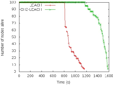
3.2.1 Network Lifetime
Lifetime of network depends on the survival time of node. When first node dies, performance of network starts declining
Algorithm 2: Dist_thresh_0()
for node i = 1 to N
if (node i was cluster head in previous rounds) then thresh(i) = 0
end if Else
thresh(i)= (𝑘/(𝑁 − 𝑘 ∗ (𝑟 𝑚𝑜𝑑 𝑁/𝑘) ) )
End else
if ((Rn(0,1) < thresh(i)) && (din < di to BS < dout)) Set node i as CH(i)
Broadcast_CHM(i)
Wait_joinreq(t)
TDMA_send(i)
end if Else
Set node i as Non_CH(i)
Wait(ti) for CH advertisement
126 but as sensor nodes are adjacent to each other and they
monitor the identical region of the network therefore by the death of a few nodes network is not fully out of service. So, network lifetime is defined by the time up to which the last node survives. Three metrics being used in this paper, FND, HNA and LND measures the lifetime period of system. Fig. (
3) shows the total nodes that stay alive over the network simulation time.
Fig. 3 Total number of nodes alive over simulation time
Fig. ( 4) shows total nodes survive per amount of data received at BS. In CHZ-LEACH, nodes survive for longer time than LEACH, since only those nodes are selected As CH which belongs to cluster head zone and have enough energy, hence send large amount of data to the BS.
Fig. 4 Total number of nodes alive per amount of data signals
received by BS
From Table 2, it is observed that FND of CHZ-LEACH is enhanced up to 370s, HNA is enhanced by 630s and LND is improved by 422s over LEACH protocol. In other words, this simulation predicts that the enhancement in FND, HNA and LND is 46%, 72% and 37% respectively over LEACH.
Table-2 Lifetime comparison (seconds)
Protocol FND HNA LND
LEACH 810 870 1156
CHZ-LEACH 1180 1500 1578
3.2.2 Data Signals received at the Base Station
For more precise environment sight, data collected at the base station should be as high as possible. Fig. ( 5) shows total amount of data received at the base station over time and better results of CHZ-LEACH than LEACH protocol, as all nodes of LEACH protocol dies after 1180s therefore, no data transmission takes place after 1180s.
Fig. 5 Total number of data signals received at the BS over simulation time
Similarly, Fig. ( 6) shows the total data signals received at the BS per unit energy, the curve of LEACH protocol after consuming 330J energy suddenly starts going down hence CHZ-LEACH deliver more data signals to the BS per unit energy in comparison of LEACH protocol, results in more latency and energy efficiency.
Fig. 6 Total number of data signals received at the BS per given amount of energy
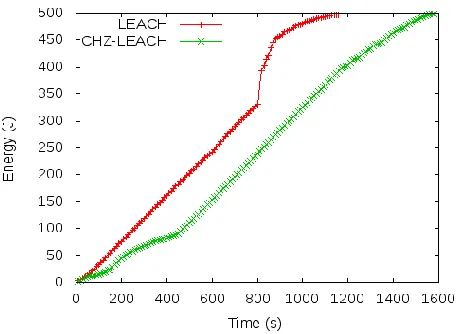
3.2.1 Energy Consumption
127 energy consumption is less and uniform in CHZ-LEACH, it is
concluded that energy load is uniformly distributed in CHZ-LEACH in comparison to CHZ-LEACH protocol.
Fig. 7 Amount of energy consumed over time
4
C
ONCLUSIONIn this paper, a new version of clustering hierarchy LEACH protocol namely CHZ-LEACH is proposed to improve process of cluster head selection considering average energy, residual energy and cluster head zone. A circular region named as cluster head zone is defined inside the network which helps in forming energy efficient clusters as distance of communication minimizes if node exist inside cluster head zone. Lifetime of the network increases as only those nodes play the role of cluster head which have enough energy to survive for that round. Simulation is carried out using NS-2.34 simulator and simulation results proves better performance, increased data delivery and uniform energy consumption in whole cycle of network achieved by CHZ-LEACH.
R
EFERENCES[1] D. Baghyalakshmi, J. Ebenezer, and S. a V Satyamurty, “Low latency and energy efficient routing protocols for wireless sensor networks,” Wirel. Commun. Sens. Comput. 2010 ICWCSC 2010 Int. Conf., pp. 1–6, 2010. [2] W. Dargie and C. Poellabauer, Fundamentals of wireless
sensor networks, vol. 54, no. 2. 2010.
[3] A. Chandrakasan et al., “Design considerations for distributed microsensor systems,” Proc. IEEE 1999 Cust. Integr. Circuits Conf. (Cat. No.99CH36327), pp. 279–286. [4] J. N. Al-Karaki and a. E. Kamal, “Routing Techniques in
Wireless Sensor Networks: A Survey,” IEEE Wirel. Commun., vol. 11, no. 6, pp. 6–28, 2004.
[5] H. Singh and D. Singh, “Taxonomy of Routing Protocols in Wireless Sensor Networks : A Survey,” pp. 822–830, 2016.
[6] W. R. Heinzelman, A. Chandrakasan, and H. Balakrishnan, “Energy-efficient communication protocol for wireless microsensor networks,” Proc. 33rd Annu. Hawaii Int. Conf. Syst. Sci., vol. vol.1, no. c, p. 10, 2000. [7] W. B. Heinzelman, A. P. Chandrakasan, S. Member, and
H. Balakrishnan, “An Application-Specific Protocol Architecture for Wireless Microsensor Networks,” vol. 1, no. 4, pp. 660–670, 2002.
[8] M. S. Ali, T. Dey, and R. Biswas, “ALEACH: Advanced LEACH routing protocol for wireless microsensor networks,” Proc. ICECE 2008 - 5th Int. Conf. Electr. Comput. Eng., vol. 0, no. December 2008, pp. 909–914, 2008.
[9] A. Wang, D. Yang, and D. Sun, “A clustering algorithm based on energy information and cluster heads expectation for wireless sensor networks,” Comput. Electr. Eng., vol. 38, no. 3, pp. 662–671, 2012.
[10] M. Tripathi, R. B. Battula, M. S. Gaur, and V. Laxmi, “Energy Efficient Clustered Routing for Wireless Sensor Network,” 2013 IEEE 9th Int. Conf. Mob. Ad-hoc Sens. Networks, pp. 330–335, 2013.
[11] S. Kumar, “DE-LEACH : Distance and Energy Aware LEACH,” vol. 88, no. 9, pp. 36–42, 2014.
[12] J. Hong, J. Kook, S. Lee, D. Kwon, and S. Yi, “T-LEACH: The method of threshold-based cluster head replacement for wireless sensor networks,” Inf. Syst. Front., vol. 11, no. 5, pp. 513–521, 2009.
[13] A. Salim, W. Osamy, and A. M. Khedr, “IBLEACH: Intra-balanced LEACH protocol for wireless sensor networks,” Wirel. Networks, vol. 20, no. 6, pp. 1515–1525, 2014. [14] M. J. Handy, M. Hasse, and D. Timmermann, “Low
Energy Adaptive Clustering Hierarchy with Deterministic Cluster Head selection,” Proceeding IEEE 4th Int. Work. Mob. Wirel. Commun. Netw., no. September, pp. 368–372, 2002.
[15] W. B. Heinzelman, “Application-Specific Protocol Architectures for Wireless Networks,” Citeseer Citeseer, no. 1995, 2000.
[16] “The Network Simulator - NS-2.34.” [Online]. Available: https://sourceforge.net/projects/nsnam/files/allinone/ ns-allinone-2.34/. [Accessed: 09-Feb-2018].