© 2017 IJSRST | Volume 3 | Issue 8 | Print ISSN: 2395-6011 | Online ISSN: 2395-602X Themed Section: Science and Technology
Design of Residential Building of G+9 Floors In Response Spectrum
Method Using ETABS 2013 Software
B. Vanitha
1, D. Mohammed Rafi
2*1M.Tech Student, Department of Civil Engineering, St.Mark Educational Institutions Society Group of Institutions, Anantapur, Andhra Pradesh, India
2Assistant Professor, Department of Civil Engineering, St.Mark Educational Institutions Society Group of Institutions, Anantapur, AndhraPradesh, India
ABSTRACT
One of the major problems that the country facing is the rapidly growing population, which necessities more facilities in the restricted availability of land. This can be solved to a certain extent with the construction of multistorey building, which can serve many people in available limited area. Hence it is the necessary requirement of multistorey building with all facilities. Hence an attempt is made in the project by DESIGN OF RESIDENTIAL BUILDING OF G+9 FLOORS IN RESPONSE SPECTRUM METHOD USING ETABS 2013 SOFTWARE. Earthquake Engineering was developed a lot from the early days and seismically analysing the structures requires specialized explicit finite element analysis software, which divides the element into very small slices and models the actual physics. The seismic analysis of the proposed building was done in the software ETABS 2013, which is one of the most Advanced software in the structural design field. The loads applied on the structure was based on IS:875(part I)-1987[dead load],IS:875(part II)-1987[live load], IS:875(part III)-1987[wind load], IS:1893-2000 [Earthquake load]. Scale factor is calculated from the design base shear (Vb) to the base shear calculated using fundamental time period (Ta).Once the analysis was completed all the structural components were designed according to Indian standard code IS:456-2000. Footing, columns, beams, slab, staircase and shear wall were designed. Ductile detailing of the structural elements was done as per code IS: 13920-1993.
Keywords: Ductility, ETABS, FEM, Seismic Analysis etc.
I.
INTRODUCTION
Civil engineering is the oldest engineering among all the engineering branches. For the past two decades information technology has bought revolutionary changes in engineering, civil engineering in not exceptional. Many softwares which are useful for civil engineering were developed such as Autocad, Staad, Etabs, SAP200, Midas, Teckla Structures etc. For analysis design, planning and detailing of the structures. In the contemporary engineering field it is necessary to have strong fundamental knowledge regarding the subject and relative software’s for economical and safe design of engineering structures. Therefore, in the present study a G+9 Residential Reinforced Cement Concrete (RCC) structure have been analysed, designed for earthquake loads using software’s ETABS 2013, AUTOCAD. Loads coming on to the structure were considered from IS 875:1987 and IS 1893-2002(I) and
the structure was designed in accordance with IS 456: 2000.
The objectives of the present study include:
1. Finalized plan and elevation of the structure
2. Analysis and design of structural elements using software’s: ETABS 2013
3. Detailing of structural elements using AutoCAD. 4. Study on earthquake response of structure.
Our project involves analysis and design of multistorey [G + 9] using a very popular designing software ETABS. We have chosen ETABS because of its following advantages:
intuitive and powerful graphical interface coupled with unmatched modelling, analytical, and design procedures, all integrated using common database. Although quick and easy for simple structures, ETABS can also handle the largest and most complex building models, including a wide range of nonlinear behaviours, making it the tool of choice for structural engineers in the building industry.
MODELING FEATURES:
The ETABS building is idealized as an assemblage of area, line and point objects. Those objects are used to represent wall, floor, column, beam, brace and link / spring physical members. The basic frame geometry is defined with reference to a simple three-dimensional grid system. With relatively simple modelling techniques, very complex framing situations may be considered. The building may be unsymmetrical and non-regulator in plan, Torsional behaviour of the floors and understory compatibility of the floors are accurately reflected in the results. The solution enforces complete three-dimensional displacement compatibility, making it possible to capture tubular effects associated with the behaviour of tall structures having relatively closely spaced columns. Semi-rigid floor diaphragms may be modelled to capture the effects of in plane floor deformations. Floor objective may span between adjacent levels to create sloped floors (ramps), which can be useful for modelling parking garage structures.
ANALYSIS FEATURES:
Static analysis for user specified vertical and lateral floor on story loads are possible. If floor elements with plate bending capability are modelled, vertical uniform loads on the floor are transferred to the beams and columns through bending of the floor elements. The program can automatically generate lateral wind and seismic load patterns to meet the requirements of various building codes. Three dimensional mode shapes and frequencies, model participation factors, direction factors and participating mass percentage are evaluated using Eigen vector or Ritz-vector analysis-Delta analysis effects may be included with static or dynamic analysis. Response spectrum analysis, linear time history analysis, nonlinear analysis and static nonlinear analysis are possible. The static nonlinear capabilities also allow you to perform incremental construction analysis, so that
forces that arise as a result of construction sequence are included. Results from the various static load cases may be combined with each other or with the results from the dynamic response dynamic response spectrum or time history method. Output may be viewed graphically, displayed in tabular output, the types of output include reactions, member forces, mode shapes, participation factors, static and dynamic story displacements and story shears inter story drifts and joint displacements, time history traces and more. Structural analysis comprises the set of physical laws and mathematics required to study and predicts the behaviour of structures. Structural analysis can be viewed more abstractly as a method to drive the engineering design process or prove the soundness of a design without a dependence on directly testing it. Structural design analysis to perform an accurate analysis a structural engineer must determine such information as structural loads, geometry, support conditions, and materials properties. The results of such an analysis typically include support reactions, stresses and displacements. This information is then compared to criteria that indicate the conditions of failure. Advanced structural analysis may examine dynamic response, stability and non-linear behaviour.
The design of the building is dependent upon the minimum requirements as prescribed in the Indian Standard Codes. The minimum requirements pertaining to the structural safety of buildings are being covered by way of laying down minimum design loads which have to be assumed for dead loads, imposed loads, and other external loads, the structure would be required to bear. Strict conformity to loading standards recommended in this code, it is hoped, will not only ensure the structural safety of the buildings which are being designed.
II.
LITERATURE REVIEW
Elements of Structural Design
concrete is strengthened(i.e. reinforced) by steel and the resultant composite mass is known as Reinforced Cement Concrete (R.C.C.) It is this combination which allows almost unlimited use of reinforced concrete in construction of buildings, bridges, tanks, dams etc., with the result that almost every civil engineer is intimately concerned with reinforced concrete (R.C.) structures. It is therefore, necessary that every civil engineer knows the basic principles involved in design of R.C. structures. So, it will be approximate to begin by reviewing the basic principles of structural design in general and then its application to reinforced concrete structures.
Engineering Structure and Structural Design
An engineering structure is an assembly of members or elements transferring load (or resisting the external actions) and providing a form, space, an enclose and/or cover to serve the desired function. Structural design is a science and art of designing, with economy and elegance, a durable structure which can safely carry the design forces and can serve the desired function satisfactorily in working environment during its intended service life span.
Objectives and Basic Requirements of Structural Design:
The objective of the structural design is to plan a structure which meets the basic requirements of structural science and those of the client or the user. The basic requirements of the structural design are as follows:
Safety: It has been the prime requirement of structural design right from the history of civilization and construction that a structure shall be so designed that it will not collapse in any way during its expected life span. Safety of structure is achieved by adequate.
Strength and stability. Besides strength, ductility of structure is also nowadays considered to be an additional desired quality from a view point that if at all failure occurs, it should not be sudden but should give prior warning of its probable occurrence so as to enable one to minimize the consequences of collapse and avoid loss of human life. Ductility is thus obtained by providing steel of such quality that it would yield prior to crushing of concrete.
Serviceability: The structure shall efficiently serve the intended function and also shall give a satisfactory performance throughout the life span. The performance is rated buy the fitness of the structure to maintain deflections, deformations, cracking and vibration effects within acceptable limits. It is achieved by providing adequate stiffness and cracking resistance.
Durability: The structure shall resist effectively environmental action during its anticipated exposure conditions, such as rain, alternate wetting and drying or freezing, climatic variations in temperature and humidity, chemical actions of salt, abrasion action etc.
Economy: The economy shall be of material by optimum utilization of its strength or it may be the economy of cost which includes cost of construction as well as cost of maintenance and repairs.
Aesthetics: The structure should be so designed that it should not only be safe, serviceable and durable but should also give a pleasing appearance without affecting the economy to a great extent.
Feasibility, Practicability and Acceptability: The structure has to be so designed that the proposed solution is feasible, practicable an acceptable.
The Design Process:
The entire process of design requires conceptual thinking, sound knowledge of engineering, relevant design codes and byelaws, backed up by experience, imagination and judgment. The codes of practice are compendia of good practice drawn by experienced and competent engineers. They are intended to guide the engineers and should not be allowed to replace their conscience and competence.
The design process commences with the planning of the structure primarily to meet its functional requirement and then designed for safety and serviceability. Thus, the design of any structure is categorized into the following two types:
user efficiently. This includes proper arrangement of rooms, halls, good ventilation, and acoustics, unobstructed view in cinema theatre / community halls, proper water supply and drainage arrangements etc.
2) Structural Design: As mentioned earlier Structural design is a science and art of designing, with economy and elegance, a durable structure which can safely carry the design forces and can serve the desired function satisfactorily in working environment during its intended service life span.
It consists of the following steps:
a) Structural Planning b) Determination of Loads c) Analysis
d) Member Design
e) Drawing, Detailing and Preparation of Schedule.
Elements of a R.C. Building Frame
The principle elements of a R.C. building frame are slab, beam, column and footing.
a) Slab: It is two-dimensional or a planar member supporting a transverse load and providing a working floor or a covering shelter. The loads are transferred to supporting beams or walls in one or both directions. b)Beam: A Beam is a one-dimensional (normally horizontal) flexural member which provides support to the slab and the vertical walls.
c) Column: It is one dimensional vertical member providing a support to beam. Load is transferred primarily by axial compression accompanied by bending and shear.
d) Footing: A footing can be considered as a horizontal two way cantilever slab providing a wide base to a column for distributing concentrated column load over a large area of supporting soil. Load transfer is affected partly by bending and partly by bearing.
Design Philosophies
Since the inception of the concept of reinforced concrete in the last twenties of the nineteenth century, the
following design philosophies have been evolved for design of R.C. structures:
a) Working Stress Method (WSM) b) Ultimate Load Method (ULM) c) Limit State Method (LSM)
Limit State Method (LSM)
The limit state method ensures the safety at ultimate load and serviceability at working load rendering the structure fit for its intended use. Thus, it considers the fitness of the structure to perform its function satisfactorily during its life span.
The salient features and the merits of the method are briefly given below:
1) It considers the actual behaviour of the structure during the entire loading history up to collapse.
2) It adopts the concept of fitness of structure to serve the desired function during the service life span and defines the limiting state of fitness as the „limit state‟. 3) It attempts to define quantitatively the margins of safety or fitness on some scientific mathematical foundations rather than on adhoc basis of experience and judgment. The mathematical basis is derived from classical reliability theory and statistical probability (e.g. the reliability of the fitness of the structure and the probability of attainment of a critical limit state).
4) The method, adopts the idea of probability of the structure becoming unfit, and attempts to achieve the minimum acceptable probability of failure.
5) The method is based on statistical probabilistic principles.
Limit State of Collapse (Ultimate Limit State)
It is the limit state on attainment of which the structure is likely to collapse. It relates to stability and ultimate strength of the structure. Design to this limit state ensures safety of structure from collapse.
The structure failure can be any of the following types:
Displacement of the structure bodily due to lack of equilibrium between the external forces and the resisting reactions (Types (c), (d), (e) given below).
The various conditions leading to structural failure are as follows:
a) Failure, breakage and hence division into segments of one or more members of the structure either due to material failure or on account of formation of mechanism by development of plastic hinges at one or more critical sections.
b) Buckling; c) Sliding; d) Overturning; e) Sinking.
This limit state is attended to by providing resistance greater than the force coming on it and keeping a margin of safety through safety factors. I.S. Code prescribes different safety factors for overturning and sliding without giving any special status to sinking or buckling.
III.
LOADS AND LOAD COMBINATIONS
Design loads for the residential building:
Loads are a primary consideration in any building design because they define the nature and magnitude of hazards are external forces that a building must resist to provide a reasonable performance(i.e., safety and serviceability) throughout the structure’s useful life. The anticipated loads are influenced by a building’s intended use (occupancy and function); configuration (size and shape) and location (climate and site conditions).Ultimately, the type and magnitude of design loads affect critical decisions such as material collection, construction details and architectural configuration. Since building codes tend to vary in their treatment of design loads the designer should, as a matter of due diligence, identify variances from both local accepted practice and the applicable code relative to design loads as presented in this guide, even though the variances may be considered technically sound.
Earthquake Loads:
Earthquake or seismic load on a building depends upon its geographical location, lateral stiffness and mass, and is reversible. Its effect should be considered along both axes of a building taken one at a time. A force is defined as the product of mass and acceleration. During an earthquake, the mass is imparted by the building whereas the acceleration is imparted by ground disturbances. In order to have a minimum force, the mass of the building should be as low as possible. There can be no control on the ground acceleration as it is an act of God! The point of application of this internal force is the center of gravity of the mass on each floor of the building. Once there is a force, there has to be an equal and opposite reaction to balance the force. The inertial force is resisted by the building and the resisting force acts at the center of rigidity at each floor of the building or shear center of the building at each storey.
There are two methods to determine the earthquake force in a building: - a) Seismic coefficient method or static method.
b) Response spectrum method or modal analysis method or spectral acceleration method or dynamic method.
Response Spectra: The representation of the maximum response of idealized single degree of freedom system having certain period of vibration and damping during a given earthquake is referred to as a response spectrum.
Load combinations:
Load combinations as per IS 875 Part 5 are taken into consideration. A judicious combination of the loads (specified in IS 875 Parts 1 to 4 of this standard and earthquake), keeping in view the probability of: a) Their acting together, and
b) Their disposition in relation to other loads and severity of stresses or
c) Deformations caused by combinations of the various loads are necessary to ensure the required safety and economy in the design of a structure.
stipulations in the relevant design codes. In the absence of such recommendations, the following loading combinations, whichever combination produces the most unfavourable effect in the building, foundation or structural member concerned may be adopted (as a general guidance ).
It should also be recognized in load combinations that the simultaneous occurrence of maximum values of wind, earthquake, imposed and snow loads is not likely:
1) DL + LL 2) DL + LL +SLX 3) DL + LL + SLY 4) DL + LL –SLX 5) DL + LL –SLY 6) 1.5 (DL + LL) 7) 1.5 (DL + SLX) 8) 1.5 (DL - SLX) 9) 1.5 (DL + SLY) 10) 1.5 (DL -SLY) 11) 0.9DL +1.5SLX 12) 0.9DL -1.5SLX 13) 0.9DL + 1.5SLY 14) 0.9DL - 1.5SLZ 15) 1.2 (DL +LL +SLX) 16) 1.2(DL +LL -SLX) 17) 1.2(DL+LL+SLY) 18) 1.2(DL + LL - SLY)
IV.
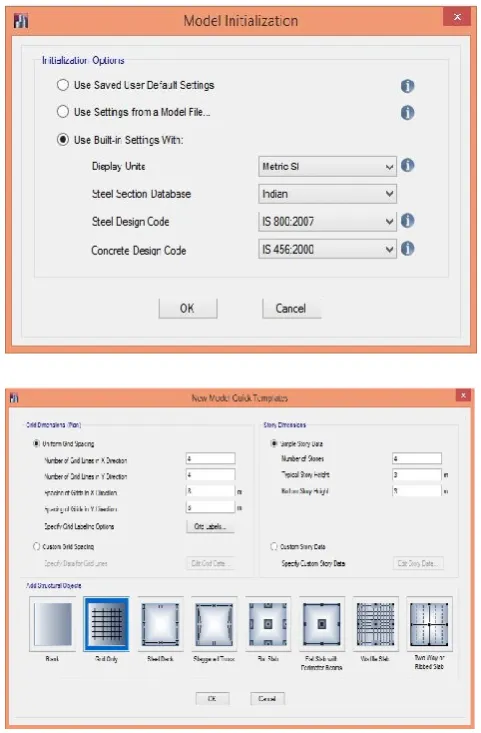
MODELLING AND ANALYSIS DEFINE
GEOMETRY:
The Building Plan Grid System and Storey Data form is used to specify horizontal and vertical grid line spacing, storey data, storey elevation and units. They automatically add the structural objects with appropriate properties to the model.
Figure 1: Building Plan Grid System and Storey Data Definition
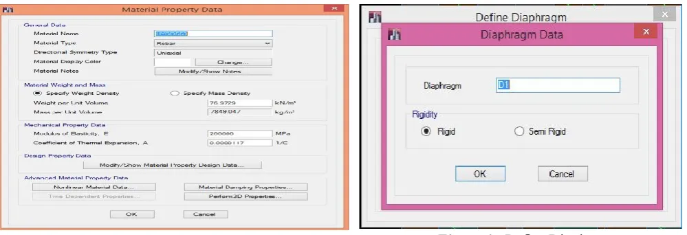
DEFINE MATERIAL PROPERTY:
Figure 2: Material property data form.
DEFINE FRAME SECTION:
Assign the frame section such as Column and Beam. Select the section property as Rectangle and define the depth, width and reinforcement details, cover provisions. Similarly for various sections like circular pipe, steel joist sections also assigned with suitable data.
Figure 3 : Section properties and Reinforcement details.
DEFINE DIAPHRAGM:
The lateral loads can be in the form of wind or seismic loads, the loads are automatically calculated from the dimensions and properties of the structure based on built-in options for a variety of building codes. For Rigid diaphragm systems, the wind loads applied at the geometric centers of each rigid floor diaphragm.
Figure 4 : Define Diaphragms
DEFINE RESPONSE SPECTRUM FUNCTION: Functions are defined to describe how a load varies as a function of period, time or frequency.
Figure 5 : Define response spectrum function.
RESPONSE SPECTRUM FUNCTIONS:
Figure 6 : Response spectrum function graph
V. MODEL OUTPUT:
A)
OUTPUT: 3D-MODEL OF A RC FRAMEFigure 7 : 3D model of RC frame
B) BENDING MOMENT DIAGRAM FROM ANALYSIS
Figure 7: Bending Moment from analysis.
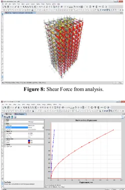
F) SHEAR FORCE FROM ANALYSIS
Figure 8: Shear Force from analysis.
Figure 9 : Story Displacement Curve under Factored Dead Load+ Live Load
V.
CONCLUSION
The Commercial building was designed with the earthquake resistant design consideration. Seismic analysis and design were done by using ETABS software as per IS 1893-2002.The detailing of the structural elements were done as per IS 13920-1993(Ductile detailing for Earthquake resistant structures). To conclude a complete design involving several parameters so as to result the earthquake has been done.
VI.
REFERENCES
[1]. IS: 875 (part I)-1987 - Code for practice for Design loads for Buildings and Structures [Dead load calculation]
[2]. IS: 875 (part 2)-1987 - Code for practice for Design loads for Buildings and Structures [Live load calculation]
[3]. IS: 875 (part 3)-1987 - Code for practice for Design loads for buildings and Structures [Wind load calculation]
[4]. IS: 456-2000 for Plain and Reinforced Concrete code for practice (IV th Revision)
[5]. IS: 1893-2002 - Criteria for Earthquake Resistant Design of structures [Seismic load calculation]
[6]. IS: 13920-1993 - Ductile Detailing of Reinforced Concrete Structures subjected to seismic forces. [7]. SP: 16- Design Aids for Reinforcement concrete
to IS: 456-1978
[8]. ETABS - Integrated Building Design software manual by Computers and Structures Inc. Earthquake Resistant Design of Structures by Mr.Pankaj Aggarwal and Mr. Manish Shirkhande.
[9]. Design of Reinforced Concrete Structures by Mr.Unnikrihna Pillai and Mr. Devadoss Menan. Design of Reinforced Concrete Elements by Mr. Krishna Raju and Mr.R.N.Pranesh.
[10]. Limit state Design of Reinforced Concrete