ANALYSIS OF COMPLEX PLANETARY CHANGE-GEARS THROUGH THE
TORQUE METHOD
Assoc. Prof. Karaivanov D. PhD., Petrova A., Ilchovska S., Konstantinov M.
Department of Applied Mechanics – University of Chemical Technology and Metallurgy, Sofia, Bulgaria [email protected]
Abstract: An alternative method for kinematic and power analysis of compound gear train is presented, which uses the torques and lever analogy of a given gear train. The method combines the accuracy of the Willis analytical method with the clarity of the graphic method of Kutzbach. Unlike these methods, the torque method allows determining not only the gear ratio, but the magnitude and direction of power flows, and hence the determination of efficiency of a given compound planetary gear train. The application of the method is illustrated with example of complex change-gear (gear-box).
Keywords: KINEMATIC ANALYSIS, POWER ANALYSIS, RATIO, EFFICIENCY, PLANETARY GEAR TRAINS, CHANGE-GEARS
1. Introduction
There are various methods for analysis of planetary gear trains (PGT) at all. Two, however, are most commonly used. One is the analytical method of Willis, the other is a graphical method of Kutzbach. Both methods have proved their worth over many years. The method of Willis (1841) [19] is used for almost two centuries and the method of Kutzbach (1927) [12] is there nearly a century.
The main advantage of analytical method is the accuracy. Moreover it is universal. However, it lacks any clarity, the volume of calculations, especially for the complex compound PGTs, is not small, which allows and there is no simple way to check the results, but the most careful repeating of the calculations.
Undoubtedly the main advantage of the graphical method is the clarity. However, it is lost for complex compound planetary gear trains because of the tangle of lines obtained. Frankly in graphical methods we cannot speak for high accuracy.
The importance of accurate analysis of all gear trains is determined by the fact that errors in defining the correct transmit ratio or in the direction of rotation of the output shaft of the train in some cases may be fatal.
The two main methods at use have advantages and disadvantages. This determined the need of proposed another method – torque method – more suitable for the practice that combine their advantages and avoid the disadvantages [1, 3, 4, 5, 6, 7, 8, 9, 10 ]. The following properties are desired:
- accuracy; - simplicity; - maximum clarity; - easy usability (relevance); - easy check of the results;
- generally the opportunity to achieve more goals than with previous methods, namely - not only determining the gear ratio, but the presence or absence of internal division or circulation of power, determining the efficiency and, in particular in gearboxes, determining the load spectrum of the elements of gear train (wheels, shafts, bearings), as a prerequisite for their reliable load capacity calculation;
The aim of this paper is illustrate the advantages of torque method in analysis of complex planetary change-gears (gear-boxes).
2. Essence of the Torque Method
Unlike the methods of Willis and Kutzbach using angular velocity
ω
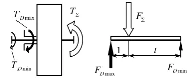
(or rotational speed n) and the peripheral velocities v, at the presented here method the torques T are used. The method is based on the following well-known principles of mechanics, illustrated with the simplest case of elementary (single-carrier) gear train with three external shafts that has a very good lever analogy (Fig. 1):a.) Equilibrium of ideal (with no account of losses) external torques acting on the three shafts
min max 0
i D D
T =T +T +TΣ=
∑
(1) wheremin
D
T
andmax
D
T are the unidirectional external ideal torques (with different sizes), therefore are indicated by single lines on the figure, but with different thickness, according to their size;
TΣ is the largest torque, in absolute value equal to the sum of other
two torques min
D
T and
max
D
T , and therefore is marked with a double line.
b.) Equilibrium of the real (considering the losses) external torques
min max 0
i D D
T′=T′ +T′ +TΣ′=
∑
(2) wheremin
D T′ ,
max
D
T′ and TΣ′ are the same external torques as above, but
real now considering the losses in the gear train.
c) Sum of ideal (not considering the losses) powers
For the simpler case, when the gear train is with one fixed shaft, i.e. working with F = 1 degree of freedom, the condition is
0
i A B A A B B
P=P +P =T ⋅
ω
+T ⋅ω
=∑
(3)where
A P,
A
T and
ω
Aare the input power, torque and angular velocity;B P,
B
T and
ω
B - the output power, torque and angular velocity; The above condition is used to determine the speed ratioA B
B A
T i
T
ω
ω
= = − (4)
d) Sum of real (considering the losses) powers 0
i A B A A B B
P′= ⋅
η
P′+P′= ⋅ ⋅η
T′ω
+T′⋅ω
=∑
(5)where
A P′ ,
A
T′ and
ω
A are the input power, torque and angular velocity;B P′,
B T′ and
B
ω
- the output power, torque and angular velocity; From this follows the formula for the efficiencyB A T
A B k
T T i
i
η
ω ω
′ ′
= − = − (6) min
D F t 1
max
D F
FΣ ТΣ
max
D Т
min
D Т
In this formula T
i means the ratio of the real external torques B T′ and
A
T′ at the input A and output B of gear train, as signified more as dynamic [11], as a power ratio or torque transformation [14, 18]. The other ratio
k
i is the usual speed ratio and unlike the above, if necessary, the index k - from the "kinematic” can be used.
To determine the real external torques i
T′ it is necessary that the directions of relative (rolling) powers
rel i
P are identified in each gear train according to the respective carrier, and each gear train has its own internal efficiency [11, 14, 18].
In most cases the direction of relative (rolling) power Prel in one planetary gear train (from the sun gear 1 to the ring gear 3 and vice versa) can be determined, proceeding from the direction of the torque on the sun gear and its relative angular velocity toward the carrier
1rel 1 H
ω
=ω ω
− , by the following simple criteria: - when the directions of the torque T1 and the relative angularvelocity ω1rel coincide i.e.
1rel T1 0
ω
⋅ > - the relative power is transmitted from the sun gear 1 through the planets 2 to the ring gear 3, or in other words, the sun gear appears to be the driving one in the relative motion;- when
1rel T1 0
ω ⋅ < - the relative power is passed from the ring gear 3 to the sun gear 1;
In relatively rare cases this situation is not that clear. Then it is appropriate for determining the direction of the relative power to use the method of the samples [17].
Along with the foregoing known principles of mechanics, the following two small but very useful innovations are made:
e) For the greatest possible illustration of the method the known symbol of the Wolf [20] (Fig. 2) is used, but modified [1, 3, 4, 5, 6, 7, 8, 9, 10 ]. The each elementary (single-carrier) gear train, which has three external shafts is depicted with a circle, from which the three shafts are coming out, marked differently from the original – i.e. not with numbers, letters or inscriptions, but by the thickness of the lines corresponding to the size of the external torque, as already mentioned above. This little innovation concerning the manner of marking the shafts makes the method very clear and useful.
f) Besides using the modified symbol of Wolf, where appropriate another innovation is made. A new torque ratio is defined – the one of the unidirectional external torques [1, 3, 8]
max
min 1 D D T t
T
= > + (7)
because
max min
D D
T >T (fig. 1).
This innovation is especially important. It is connected to the lever analogy.
g) Ideal external torques are always in a certain ratio, expressed with the torque ratio t
(
)
(
)
min: max: 1: 1: 1 1 1: : 1
D D
T T TΣ=T + ⋅t T − +t T = + − +t t (8)
in which always
min max
D D
T <T <TΣ (9)
however:
- How many degrees of freedom F (F = 1 or F = 2) the gear train is running with;
- Which shaft is fixed at F = 1 degree of freedom;
- What is the direction of power flow, respectively does the gear train works as a reducer or a multiplier at F = 1 degree of freedom, respectively such as a collecting or as a separating gear at F = 2 degrees of freedom, i.e. as a differential;
- Does the gear works as a single or as a component train along with others in a compound planetary gear train.
3. Application of the Torque Method
The application of the torque method is best illustrated in [6, 7]. Main points as determination of relative power direction in component planetary gear trains, circulation or division of power, etc. are presented and explained.
Coefficient of efficiency of the PGTs is in direct proportion of the coefficient of internal losses
ψ
0 and the basic (internal)coefficient of efficiency 0
η
. This is the coefficient of efficiency of the PGT at immovable carrier H (ω
H =0), i.e. gear as normal, nonplanetary. When losses in the meshing prevail, the basic coefficient of efficiency0
η
is calculated starting from the coefficients of overlappingε
α of the two meshings - external andinternal, and the coefficient of friction
µ
z of the meshing [30, 34, 35, 36 and 37]. There is also a simplified formula for determining the basic (internal) coefficient of efficiency [14 and 32]0 0
1 3 2 3
1 1 1 1
1 1 0,15 0, 2
z z z z
η
= −ψ
≈ − + + −
. (10)
For the coefficient of efficiency determination of the PGT according to the torque method the real external torques (considering losses) must be determined, for which you need to know the direction of power transmission with respect to the carrier H, i. e. the relative power Prel. There are two options – it is transmitted from the sun gear 1 through the planets 2 of the ring gear 3 or vice versa. Using basic (internal) coefficient of efficiency
0
η
for these two cases, the following relations are obtained for the real external torques3 0 1
T′= ⋅ ⋅
η
t T′ - when the relative power is transmitted from 1 to 3;3
1 0
T T
t
η
′′= - when the relative power is transmitted from 3 to 1.
The very direction of the relative power rel
P transmission is defined by the following criteria - a match or mismatch of the direction of the torque T1 of the sun gear 1 with the direction of the
relative angular velocity
ω
1rel=
ω ω
1−
H with respect to the carrierH
.
Problems of the power circulation are explained in [2].
4. Analysis of the Four Stage Planetary
Change-Gear Train through the Torque Method
Figure 3 presents a four-carrier planetary change-gear train (kinematic scheme).
Ideal torques, real torques, check their values by formulae (3) and (5), speed and torque ratios and efficiency for all ways of operating are determined (Figs. 4, 5, 6 and 7). The basic efficiency
of all stages are chosen equal each other
0I 0II 0III 0IV 0, 97
η
=η
=η
=η
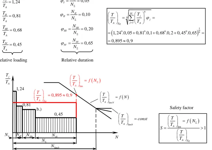
= .Figure 8 shows how to determine the load spectrum of an element of the change-gear while working with different gear-ratio steps (speeds).
ТΣ
min
D
Т
max
D
Т
1 t> +
Fig. 3. A four-carrier planetary change-gear with four gear-ratio steps (speeds)
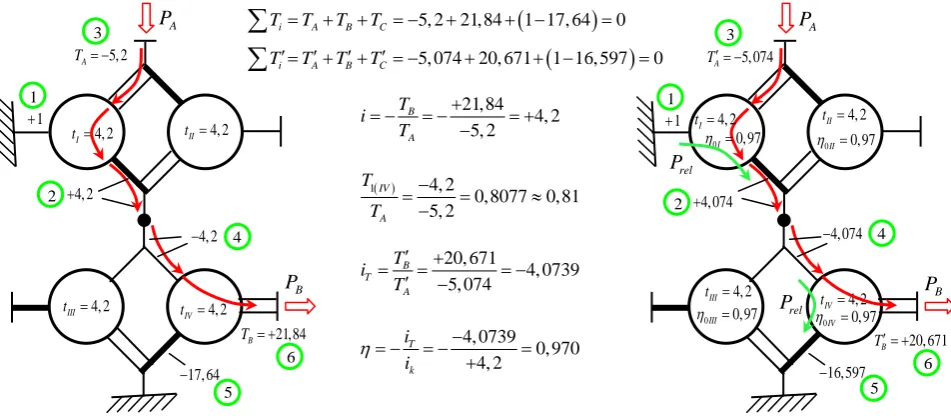
Fig. 4. Ideal and real torques, speed and torque ratios and efficiency of “first speed” of the planetary change-gear from Fig.3
Fig. 5. Ideal and real torques, speed and torque ratios and efficiency of “second speed” of the planetary change-gear from Fig.3
21,84 4, 2 5, 2 B
A T i
T
+
= − = − = +
−
( )
1 4, 2
0,8077 0,81 5, 2
IV A T
T
−
= = ≈
− 4, 2
II
t =
5, 2 A
T = −
4, 2
+
1
+
17, 64
−
1
2 3
4 4, 2
−
5
21,84 B
T = +
4, 2 I
t =
A
P
B
P
4, 2 IV
t =
4, 2 III
t =
6
4, 2 II
t =
5, 074 A
T′ = −
4, 074
+
1
+
16,597
−
1
2 3
4 4, 074
−
5
20, 671 B
T′ = +
A
P
B
P
4, 2 IV
t =
4, 2 III
t =
6 4, 2
I
t =
0I 0,97 η =
rel
P
0II 0,97 η =
0III 0,97
η = η =0IV 0,97
rel
P
20, 671
4, 0739 5, 074
B T
A T i
T
′ +
= = = −
′ −
4, 0739 0, 970 4, 2
T k i i
η= − = −− =
+
(
)
5, 2 21,84 1 17, 64 0
i A B C
T =T +T +T = − + + − =
∑
(
)
5, 074 20, 671 1 16, 597 0
i A B C
T′=T′+T′+T′= − + + − =
∑
27, 044 B
T′ = −
4,33 A
T′ = +
5,33
−
4, 2 I
t =
A
P
1
+
21, 714
+
B
P
4, 2 III
t =
1 2
3
4
6 5,33
+
5 0II 0,97 η =
rel
P
0IV 0,97
η =
rel
P
4, 2 II
t =
4, 2 IV
t =
0I 0,97 η =
0III 0,97 η =
27, 04 B
T = −
4, 2 A
T = +
5, 2
−
4, 2 I
t =
A
P
1
+
21,84
+
B
P
4, 2 IV
t =
4, 2 III
t =
4, 2 II
t =
1 2
3
4
6 5, 2
+
5
27, 04
6, 438 4, 2
B A T i
T
−
= − = − = +
+
27, 044
6, 2457 4, 33
B T
A T i
T
′ −
= = = −
′ +
6, 2457
0, 9701 6, 438
T k i i
η= − = −− =
+
(
)
4, 2 27, 04 1 21,84 0
i A B C
T =T +T +T = − + + =
∑
(
)
4, 33 27, 044 1 21, 714 0
i A B C
T′=T′+T′+T′= − + + =
∑
( )
1 5, 2
1, 238 1, 24 4, 2
IV A T
T
+
= = ≈
+
I II III IV
A
Fig. 6. Ideal and real torques, speed and torque ratios and efficiency of “third speed” of the planetary change-gear from Fig.3
Fig. 7. Ideal and real torques, speed and torque ratios and efficiency of “fourth speed” of the planetary change-gear from Fig.3
Fig. 8. Determination of load spectrum of an element (sun gear of the fourth stage) of four-carrier change-gear while working with different gear-ratio steps (speeds) B
P
AP
relP
relP
2, 796 AT = +
4, 074 + 1 + 1 2 3 4 2, 245 + 5 5, 074 − 1, 245 + 7 2, 245 − 0,551 − 8 9 10 4, 2 II t = 6,319 B
T = −
4, 2 IV t = 6 4, 2 I t = 4, 2 III t =
0III 0,97 η =
rel
P
0IV 0,97
η =
0I 0,97
η = η =II 0,97
5, 074 + 6, 438 2, 323 2, 771 B A T i T − = − = − ≈ + + ( )
1 1, 238
0, 4469 0, 45 2, 77 IV A T T + = = ≈ + 6, 319 2, 260 2, 796 B T A T i T ′ − = = = − ′ + 2, 26 0, 9729 2, 323 T k i i η= − = − − ≈ +
(
)
2, 771 6, 438 0, 533 4, 2 0
i A B C
T =T +T +T = − + − + =
∑
(
)
2, 796 6, 319 0, 551 4, 074 0
i A B C
T′=T′+T′+T′= − + − + =
∑
2, 771 A
T = +
4, 2 + 1 + 5, 2 + 1 2 3 4 2, 238 + 5 5, 2 − 1, 238 + 7 2, 238 − 0,533 − 8 9 10 4, 2 II t = 6, 438 B
T = −
B
P
4, 2 IV t = 4, 2 III t = 6 AP
4, 2 I t = 1,808 AT = +
4, 2 + 1 + 5, 2 + 1 2 3 4 2, 238 + 5 5, 2 − 1, 238 + 7 2, 238 − 0, 430 + 8 9 10 4, 2 II t = 6, 438 B
T = −
4, 2 I t = B
P
4, 2 III t = 6 4, 2 IV t = AP
1,824 AT = +
4, 074 + 1 + 5, 074 + 1 2 3 4 2, 245 + 5 5, 074 − 1, 245 + 7 2, 245 − 0, 421 + 8 9 10 4, 2 II t = 4, 2 I t = B
P
4, 2 III t = 6 AP
0I 0,97
η = η =0II 0,97
0III 0,97
η = tIV=4, 2
0IV 0,97
η = rel
P
relP
relP
6,319 BT′ = − 6, 438 3, 561 1,808 B A T i T − = − = − ≈ + + ( )
1 1, 238
0, 6847 0, 68 1,808 IV A T T + = = ≈ + 6, 319 3, 4644 1,824 B T A T i T ′ − = = = − ′ + 3, 4644 0, 9729 3, 561 T k i i η= − = −− = +
(
)
1,808 6, 438 0, 43 4, 2 0
i A B C
T =T +T +T = − + + =
∑
(
)
1,824 6, 319 0, 421 4, 074 0
i A B C
T′=T′+T′+T′= − + + =
∑
( ) lim 1 A A Eq T f N T S T T Σ = = > Safety factor ( ) lim A N T f N T = ( ) lim A T f N T Σ = lim A b T const T = N limb N NΣ IV N III N II N I N j A T T0,895 0, 9 A Eq T T = ≈ 1, 24 0,81 b.) 0, 45 0, 05 I I N N ϕ Σ = = 0,10 II II N N ϕ Σ = = 0, 20 III III N N ϕ Σ = = 0, 65 IV IV N N ϕ Σ = = 1, 24 I A T T = 0,81 II A T T = 0, 68 III A T T = 0, 45 IV A T T =
(
)
9 9 19 9 9 9 9
1, 24 .0, 05 0,81 .0,1 0, 68 .0, 2 0, 45 .0, 65
0,895 0, 9 IV
j j j I
A Eq A
T T
T = T ϕ
= = = + + + = = ≈
∑
When the change-gear from Fig. 3 works at “first speed” (Fig. 4) power pass through II and IV stage which operated with F = 1 degrees of freedom as in series connected planetary gear train. At “second speed” (Fig. 5) power pass through I and IV stage which operated with F = 1 degrees of freedom as in series connected planetary gear train too. In the other two cases (Figs. 6 and 7) the IV stage works with F = 2 degrees of freedom and power pass through the loop (III and IV stage) with division.
All four simple planetary gear trains operate with movable carrier and their relative powers are less then relevant absolute powers. Because this the efficiency of change-gear
η
is practicallyequal (a little bit bigger) to basic efficiency
η
0 of the connectedsimple planetary gear trains.
5. Conclusion
Unlike the most commonly used methods of Willis and Kutzbach-Smirnov that use the angular and peripheral velocities, at the presented torque method here another parameter of mechanics is used – the torque. This alternative method is characterized with the following:
1. The method is characterized by simplicity, maximum clarity and ease of usability (relevance), combining in itself, accuracy and clarity, existing separately in the Willis and Kutzbach-Smirnov’s methods.
2. The method allows achieving more goals than is possible with the methods of Willis and Kutzbach-Smirnov - determining not only the speed ratio, but also the internal power flows by size and direction, as a prerequisite for the determination of the efficiency. Also the determining of the load spectra of elements of the compound change-gears – gear-wheels, shafts and bearings, while working with different gear-ratio steps (speeds) as a prerequisite for their reliable load capacity calculation.
3. The dependence of the designer on a particular literary source is avoided, so he may act independently.
4. The method allows easy verification of calculations by the conditions of equilibrium of the ideal and real external torques.
5. Because of the clarity and ease applicability, the method is suitable either for industry - for engineers, or for learning process - for students.
Considering all these possibilities and the current acceptance of the torque method in different countries (Giger 2007, Müller 1998, Troha 2011), there is reason to believe that the torque method can successfully compete with those of Willis and Kutzbach-Smirnov, especially in the analysis of complex compound planetary gear trains.
Acknowledgments
The authors would like to express their deepest gratitude to the governing body of University of Chemical Technology and Metallurgy – Sofia for support in the research within the scientific grant 11432/2015 of the Research-Development Sector of UCTM
References
1. ARNAUDOV, K. and D. KARAIVANOV. Engineering
analysis of the coupled two-carrier planetary gearing through the lever analogy. Proceedings of the Int. Conf. on Mechanical Transmissions, Chongqing [China]: China Machine Press, 5 –9 Apr., 2001, p. 44-49.
2. ARNAUDOW, K. and D. KARAIVANOV. Die Blindleistung in Planetengetrieben. Proceedings of the Conference on Research and Development of Machine Elements and Systems IRMES’04. Kragujevac [Serbia & Montenegro], 16-17 Sep., 2004, pp. 587-594.
3. ARNAUDOW, K. and D. KARAIVANOV. r. Systematik,
Eigenschaften und Möglichkeiten von zusammengesetzten Mehrsteg-Planetengetrieben. Antriebstechnik. 2005, Nr. 5, S. 58-65.
4. ARNAUDOV, K. and D. KARAIVANOV. Higher compound planetary gear trains. VDI-Berichte 1904-1, 2005, pp. 327-344. ISSN 0083-5560
5. ARNAUDOV, K. and D. KARAIVANOV. The complex
compound multi-carrier planetary gear trains – a simple study. VDI–Berichte 2108 – 2, 2010, pp. 673-684. ISSN 0083-5560 6. ARNAUDOV, K. and D. KARAIVANOV. Alternative method
for analysis of complex compound planetary gear trains: Essence and possibilities. Mechanisms and Machine Science, 13 (2013), Power Transmissions, Proceedings of the 4th International Conference, Sinaia, Romania, June 20-23, 2012, Editor Georg Dobre, Springer Dordrecht Heidelberg New York London, p. 3-20 (Plenary Paper). ISSN 2211-0984.
7. ARNAUDOV, K. and D. KARAIVANOV. The torque method used for studying coupled two-carrier planetary gear trains. Transactions of FAMENA. 2013, 37 (1), No. 1, pp. 49-61. ISSN 1333-1124.
8. KARAIVANOV, D. Theoretical and experimental studies of the influence of the structure of coupled two-carrier planetary gear trains on its basic parameters. Dissertation. Sofia: Univ. of Chemical Technology and Metallurgy, 2000. (in Bulgarian) 9. KARAIVANOV, D. Structural analysis of the coupled
planetary gears with considering the efficiency of the coupling gears. Proceedings of the 2th Int. Conf. on Manufacturing Engineering (ICMEN), Kallithea of Chalkidiki [Greece], October 5 – 7, 2005, pp. 381-387. ISBN 960-243-615-8.
10.KARAIVANOV, D. Structural Analysis of Compound
Planetary Gear Trains. Balkan Journal of Mechanical Transmissions, 2011, 1 (1), pp. 33-45. ISSN 2069-5497.
11.KUDRYAVTSEV, V. N. and Y. N. KIRDYASHEV. Planetary trains. Handbook. Leningrad: Mashinostroenie, 1977.
12.KUTZBACH, K. Mehrgliedrige Radgetriebe und ihre Gesetze. Maschinenbau. 1927, Nr. 22, S. 1080.
13.LEISTNER, F., G. LÖRSCH and O. WILHELM.
Umlaufrädergetriebe. 3. Auflage. Berlin: VEB Verlag Technik, 1987.
14.LOOMAN, J. Zahnradgetriebe – Grundlagen, Konstruktion, Anwendung in Fahrzeugen. 3. Auflage, Berlin: Springer-Verlag, 1996.
15.MÜLLER, H. W. Epicyclic drive trains. Detroit: Wayne State University Press, 1992.
16.NIEMANN, G. and H. WINTER. Maschinenelemente. Band 2. Zahnradgetriebe – Grundlagen, Stirnradgetriebe. 2. Auflage. Berlin: Springer-Verlag, 1995.
17.SEELIGER, K. Das einfache Planetengetriebe. Antriebstechnik. 1964, S. 216-221.
18.VDI-Richtlinie 2157 Planetengetriebe – Begriffe, Symbole, Berechnungsgrundlagen, Entwurf. 2010
19.WILLIS, R. Principles of Mechanism. London: John W. Parker, 1841.
20.WOLF, A. Die Grundgesetze der Umlaufgetriebe.