DOI 10.1007/s11036-008-0121-x
A Control Theoretic Approach for Throughput
Optimization in IEEE 802.11e EDCA WLANs
Paul Patras·Albert Banchs·Pablo Serrano
Published online: 9 December 2008
© Springer Science + Business Media, LLC 2008
Abstract The MAC layer of the 802.11 standard, based
on the CSMA/CA mechanism, specifies a set of para-meters to control the aggressiveness of stations when trying to access the channel. However, these parame-ters are statically set independently of the conditions of the WLAN (e.g. the number of contending stations), leading to poor performance for most scenarios. To overcome this limitation previous work proposes to adapt the value of one of those parameters, namely the CW, based on an estimation of the conditions of the WLAN. However, these approaches suffer from two major drawbacks: i) they require extending the capabil-ities of standard devices or ii) are based on heuristics. In this paper we propose a control theoretic approach to adapt the CW to the conditions of the WLAN, based on an analytical model of its operation, that is fully compliant with the 802.11e standard. We use a Proportional Integrator controller in order to drive the WLAN to its optimal point of operation and perform a theoretic analysis to determine its configuration. We show by means of an exhaustive performance evalua-tion that our algorithm maximizes the total throughput of the WLAN and substantially outperforms previous standard-compliant proposals.
P. Patras (
B
)IMDEA Networks, Avenida del Mar Mediterráneo, 22, 28918 Leganés, Madrid, Spain
e-mail: [email protected] P. Patras·A. Banchs·P. Serrano Universidad Carlos III de Madrid, Leganés, Madrid, Spain
Keywords wireless LAN·802.11·802.11e·EDCA·
control theory·throughput performance· throughput optimization
1 Introduction
The CSMA/CA mechanism used in IEEE 802.11 WLANs is based upon a set of parameters that con-trols the way stations access the channel. In particular, the Contention Window (CW) parameter controls the probability that a station defers or transmits a frame once the medium has become idle.
The CW configuration used by the 802.11 standard [1] is statically set, independently of the number of con-tending stations. This static configuration leads to poor performance in most scenarios. In particular, when there are many stations in the WLAN it would be desir-able to have larger CWs in order to avoid too frequent collisions, while with few stations smaller CWs would help to reduce the channel idle time. Following this, it has been shown that for given a number of actively contending stations there exists an optimal CW config-uration that maximizes throughput performance [2,3].
Following the above observations, many authors have proposed to dynamically adapt the CW by esti-mating the number of active stations in the WLAN. These works can be classified in two different groups:
2. Centralized approaches [14,15], based on a single node that periodically distributes the set of MAC layer parameters to be used by every station. These approaches are compatible with the 802.11e stan-dard. However, because they are based on heuristic algorithms and lack analytical support, they do not guarantee optimal performance.
In this paper we propose a novel adaptive algorithm to dynamically adjust the CW configuration of 802.11-based Wireless LANs. We share the same goal with previous approaches, i.e., to maximize the overall throughput performance of the wireless network. Com-pared to the existing schemes our proposal benefits from the following key improvements:
– It is fully compatible with the 802.11e standard and does not require any modification to existing hardware, since the dynamic adjustment is based only on observing successfully received frames at the Access Point (AP).
– It is based on a well established scheme from discrete-time control theory, namely the Propor-tional Integrator (PI). We optimally tune the para-meters of the PI controller by conducting a control theoretic analysis of the system.
The rest of the paper is structured as follows. In Section 2 we briefly describe the EDCA mechanism of the IEEE 802.11e standard. In Section 3 we ana-lyze the throughput performance of EDCA and find the collision probability for which this is optimized. In Section 4 we present the proposed algorithm, which aims at driving the system to the optimal collision prob-ability obtained in the previous section by using a PI controller. The parameters of the controller are set fol-lowing a control theoretical analysis of our system. The performance of the proposed scheme is validated by means of simulation experiments in Section5. Finally, Section6concludes the paper.
2 IEEE 802.11e EDCA
This section briefly summarizes the EDCA mechanism. This mechanism has been defined in the 802.11e stan-dard [16] and will be included in the ongoing new revision of the 802.11 standard [17].
EDCA regulates the access to the wireless channel on the basis of the channel access functions (CAFs). A station may run up to 4 CAFs, and each of the frames generated by the station is mapped to one of them. Once a station becomes active, each CAF executes an independent backoff process to transmit its frames.
A station with a new frame to transmit monitors the channel activity. If the medium is idle for a period of time equal to the arbitration interframe space para-meter ( AI F S), the CAF transmits. Otherwise, if the channel is sensed busy (either immediately or during the AI F S period), the CAF continues to monitor the channel until it is measured idle for an AI F S time, and, at this point, the backoff process starts.
Upon starting the backoff process, a random value uniformly distributed in the range(0,CW−1)is cho-sen and the backoff time counter is initialized with this number. The CW value is called the contention window, and depends on the number of failed trans-missions of a frame. At the first transmission attempt,
CW is set equal to the minimum contention window
parameter (CWmin).
As long as the channel is sensed idle, the backoff time counter is decremented once every empty slot time
Te. When a transmission is detected on the channel the
backoff time counter is “frozen”, and reactivated again after the channel is sensed idle for a certain period. This period is equal to AI F S if the transmission is received with a correct FCS, and EI F S−DI F S+AI F S
other-wise, where EI F S (the extended interframe space) and
DI F S (the distributed interframe space) are physical
layer constants.
As soon as the backoff time counter reaches zero, the CAF transmits its frame. A collision occurs when two or more CAFs start transmitting simultaneously. An acknowledgement (Ack) frame is used to notify the transmitting station that the frame has been success-fully received. The Ack is immediately sent upon the reception of the frame, after a period of time equal to the physical layer constant SIFS (the short interframe space).
If the Ack is not received within a time interval given by the Ack_Timeout physical layer constant, the CAF assumes that the frame was not received successfully. The transmission is then rescheduled by reentering the backoff process, which starts at an AI F S time following the timeout expiry. After each unsuccessful transmis-sion, CW is doubled, up to a maximum value given by the CWmaxparameter. If the number of failed attempts
reaches a predetermined retry limit R, the frame is discarded.
to send a new frame a SIFS period after the completion of the previous one. The period of time a CAF is allowed to retain the right to access the channel is limited by the transmission opportunity limit parameter (T X OP_limit).
In the case of a single station running more than one channel access function, if the backoff time counters of two or more CAFs reach zero at the same time, a sched-uler inside the station avoids the internal collision by granting the access to the channel to the highest priority CAF. The other CAFs of the station involved in the internal collision react as if there had been a collision on the channel, doubling their CW and restarting the backoff process.
As it can be seen from the description of EDCA given in this section, the behavior of a CAF depends on a number of parameters, namely CWmin, CWmax, AI F S
and T X OP_limit. These are configurable parameters that can be set to different values for different CAFs. The CAFs are grouped by Access Categories (ACs), all the CAFs of an AC having the same configuration. The Access Point (AP) announces periodically (every 100 ms) the parameters of each AC by means of beacon frames.
In this paper, our goal is to find the EDCA para-meters that maximize the throughput of the WLAN, while fairly sharing the bandwidth among the compet-ing stations. Followcompet-ing this goal, we use the followcompet-ing configuration for the stations:1
– Each station executes a single CAF and transmits one frame upon accessing the channel.
– The AI F S parameter is set to the minimum value (DIFS) for all stations.
– All stations contend with the same CWmin and
CWmaxparameters.
The rest of the paper is devoted to the design of an adaptive algorithm that adjusts the configuration of CWmin and CWmax with the goal of maximizing the
overall WLAN throughput. This algorithm is executed at the AP, which uses beacon frames to announce the computed CWminand CWmaxvalues to the stations.
3 Throughput analysis and optimization
In this section we present a throughput analysis of an EDCA WLAN configured according to the rules given in the previous section. Based on this analysis, we
1The reader is referred to [18] for a detailed justification of these
configuration choices.
find the collision probability of an optimally configured WLAN, which is the basis of the algorithm presented in the following section.
We start by analyzing the case when all stations are saturated2 and consider later the case when some
stations are not saturated. Let us defineτ as the prob-ability that a saturated station transmits at a randomly chosen slot time. This can be computed according to [2] as follows:
τ = 2
1+W+pWim=−01(2p)i (1)
where W=CWmin, m is the maximum backoff stage
(CWmax=2mCWmin) and p is the probability that a
transmission collides. In a WLAN with n stations,
p=1−(1−τ)n−1 (2)
The throughput obtained by a station can be com-puted as follows
r= Psl
PsTs+PcTc+PeTe
(3)
where l is the packet length, Ps, Pc and Pe are the
probabilities of a success, a collision and an empty slot time, respectively, and Ts, Tcand Teare the respective
slot time durations.
The probabilities Ps, Pcand Peare computed as
Ps=nτ(1−τ)n−1 (4)
Pe=(1−τ)n (5)
Pc=1−nτ(1−τ)n−1−(1−τ)n (6)
and the slot time durations Tsand Tcas
Ts=TPLC P+
H
C +
l
C +SI F S+TPLC P
+ Ack
C +DI F S (7)
Tc=TPLC P+
H
C +
l
C +DI F S (8)
where TPLC Pis the PLCP (Physical Layer Convergence
Protocol) preamble and header transmission time, H is the MAC overhead (header and FCS), Ack is the size of the acknowledgement frame and C is the channel bit rate.
2Following [2], by saturation we mean that a station always has a
The above terminates our throughput analysis. We next address, based on this analysis, the issue of opti-mizing the throughput performance of the WLAN. To this aim, we can rearrange Eq.3to obtain
r= l
Ts−Tc+ Pe
Te−Tc
+Tc
Ps
(9)
As l, Ts, and Tcare constants, maximizing the
follow-ing expression will result in the maximization of r,
ˆ
r= Ps
Pe
Te−Tc
+Tc
(10)
Givenτ 1,r can be approximated byˆ
ˆ
r= nτ−n(n−1)τ
2
Te−n
Te−Tc
τ +n(n−1)
2
Te−Tc
τ2 (11)
The optimal value ofτ, τopt, that maximizes r canˆ
then be obtained by
drˆ dτ
τ=τopt
=0 (12)
which neglecting the terms of higher order than 2 yields
aτ2+bτ+c=0 (13)
where
a= −n
2(n−1)
2
Tc−Te
(14)
b = −2n(n−1)Te (15)
c=nTe (16)
Isolatingτoptfrom the above yields
τopt=
2Te
n(Tc−Te)
2
+ 2Te
n(n−1) (Tc−Te)
− 2Te
n(Tc−Te)
(17)
Given TeTc, we finally obtain the following
approximate solution for the optimalτ,
τopt≈
1
n
2Te
Tc
(18)
With the aboveτopt, the corresponding optimal
colli-sion probability is equal to
popt=1−(1−τopt)n−1=1− 1−
1
n
2Te
Tc
n−1
(19)
which can be approximated by
popt≈1−e−
2Te
Tc (20)
This implies that, under optimal operation with satu-rated stations, the collision probability in the WLAN is a constant independent of the number of stations. The key approximation of this paper is to assume that, when some of the stations are saturated and some are not, the optimal collision of the WLAN takes the same constant value.
In the following section we design an adaptive algo-rithm that adjusts the WLAN configuration with the goal of driving the collision probability to the above value. Note that, since this a constant value, our algo-rithm does not need to know the number of stations in the WLAN.
4 Adaptive algorithm
We next present our adaptive algorithm; this algorithm runs at the AP and consists of the following two steps which are executed iteratively:
– During the period between two beacon frames (which lasts 100 ms), the AP measures the collision probability of the WLAN resulting from the cur-rent CW configuration.
– At the end of this period, the AP computes the new CW configuration based on the measured collision probability and distributes it to the stations in a new beacon frame.
Our algorithm uses a PI controller to drive the WLAN to its optimal point of operation. In the follow-ing, we explain how the CW configuration is adjusted using a control signal. We then describe our system from a control theoretical standpoint. Next, we analyze our system by linearizing the behavior of the WLAN. Finally, we use this analysis to adequately configure the parameters of the PI controller.
4.1 CW configuration
Following the previous section, our goal is to adjust the CW parameters of EDCA (CWmin and CWmax) in
Since the default CW values given by the 802.11e standard3 (CWde f ault
min and CW de f ault
max ) are typically too
small, yielding a too aggressive behavior, in order to achieve optimal operation these CW parameters should be increased.
Following the above reasoning, our algorithm in-creases the default CWmin of the standard by some
CWo f f set,
CWmin=CWminde f ault+CWo f f set (21)
while keeping the default value for the maximum back-off stage, i.e.
CWmax=2mCWmin (22)
where m is the maximum backoff stage of the default configuration.
In order to ensure that our algorithm never under-performs the standard default configuration by using overly small CW values, we force that CWo f f set cannot
take negative values, which guarantees that CWminwill
never take smaller values than the standard’s default. In addition, we also force that CWo f f setcannot take values
that yield a CWminlarger than CW de f ault
max . These bounds
provide a safeguard against too large and too small values of CWmin, respectively. In the rest of the paper
we assume that CWo f f set always takes values within
these bounds and do not further consider this effect.
4.2 Control system
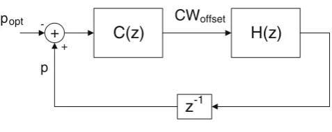
From a control theoretic standpoint, our system can be seen as the composition of the two modules depicted in Fig. 1: the controller C(z), which is the adaptive algorithm that controls the WLAN, and the controlled
system H(z), which is the WLAN itself. In our proposal
we use for the controller module a classical scheme from discrete-time control theory, namely the
Propor-tional Integrator (PI) Controller.
Following the above, our control system consists of the following two modules:
– The controller module located at the AP, that is based on the Proportional Integrator (PI) con-troller. The AP estimates the collision probability and provides it to the controller, which takes as input the difference between the estimated colli-sion probability and its desired value as given by
3Although the 802.11e parameters are configurable, the standard
includes a default setting for these parameters [16].
C(z)
H(z)
z
-1 +
-+
popt
p
CWoffset
Figure 1 Control system
Eq.20. With this input, the controller computes the
CWo f f setvalue.
– The controlled module is the 802.11e EDCA WLAN system. As specified by the standard, the AP distributes the new CW configuration to the sta-tions every 100 ms. This configuration is obtained from the CWo f f set value given by the controller,
following Eqs.21and22.
The estimation of the collision probability over a 100 ms period is performed at the AP as follows. Let S be the number of frames received by the AP during this period with the retry bit unset, and R be the number of frames received with the retry bit set. Then, if we assume that no frames are discarded due to reaching the retry limit, the collision probability p can be com-puted as
p= R
R+S (23)
since the above is precisely the probability that the first transmission attempt of a frame collides.
Note that with the above method, the AP can com-pute the probability p by simply analyzing the header of the frames successfully received, which can be easily done with no modifications to the AP’s hardware and driver.
4.3 Transfer function characterization
In order to analyze our system from a control theoretic standpoint, we need to characterize the Wireless LAN system with a transfer function that takes CWo f f set
as input and gives the collision probability p as out-put. Since the collision probability is measured every 100 ms interval, we can safely assume that the obtained measurement corresponds to stationary conditions and therefore the system does not have any memory. With this assumption,
whereτ is a function of CWo f f setas given by Eq.1,
τ = 2
1+CWminde f ault+CWo f f set 1+pmi=−01(2p)i
(25)
The above equations give a nonlinear relationship between p and CWo f f set. In order to express this
tionship as a transfer function, we linearize this rela-tionship when the system is perturbed around its stable point of operation,4i.e.
CWo f f set=CWo f f set,opt+δCWo f f set (26)
where CWo f f set,opt is the CWo f f setvalue that yields the
optimal collision probability poptcomputed in Eq.20.
With the above, the oscillations of the collision prob-ability around its point of operation poptcan be
approx-imated by
p≈popt+ ∂
p ∂CWo f f setδ
CWo f f set (27)
The above partial derivative can be computed as
∂p
∂CWo f f set =
∂p
∂τ ∂τ ∂CWo f f set
(28)
where
∂p
∂τ ≈n−1 (29)
and
∂τ
∂CWo f f set = −
21+pim=−01(2p)i
1+CWmin
1+pim=−01(2p)i2
(30)
Evaluating the partial derivative at the stable point of operation p=popt, and using the approximation
popt≈(n−1)τopt given by Eq. 19 and the expression
forτoptgiven by Eq.1, yields
∂p
∂CWo f f set ≈ −
poptτopt
1+poptim=−01(2popt)i
2 (31)
4A similar approach was used in [19] to analyze RED from a
control theoretical standpoint.
If we now consider the transfer function that allows us to characterize the perturbations of p around its sta-ble point of operation as a function of the perturbations in CWo f f set,
δP(z)=H(z) δCWo f f set(z) (32)
we obtain from Eqs.27and31the following expression for the transfer function,
H(z)= −poptτopt
1+popt
m−1
i=0
2popt
i
2 (33)
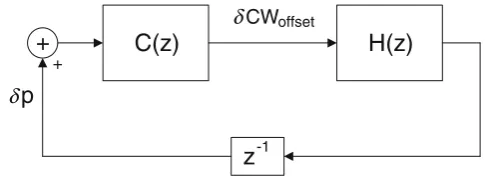
Figure2illustrates the above linearized model when working around its stable operation point:
p=popt+δp
CWo f f set=CWo f f set,opt+δCWo f f set
(34)
Note that, as compared to the model of Fig. 1, in Fig.2only the perturbations around the stable opera-tion point are considered.
4.4 Controller configuration
We next address the issue of configuring the PI controller. The transfer function of the controller is given by
C(z)=Kp+
Ki
z−1 (35)
We observe from the above transfer function that the PI controller depends on the following two parameters to be configured: Kp and Ki. Our goal in the
configu-ration of these parameters is to find the right tradeoff between speed of reaction to changes and stability. To this aim, we use the Ziegler-Nichols rules [20] which have been designed for this purpose. These rules are applied as follows. First, we compute the parameter Ku,
defined as the Kp value that leads to instability when
Ki=0, and the parameter Ti, defined as the oscillation
C(z)
H(z)
z
-1+
+
p
δCW δ offset
period under these conditions. Then, Kp and Ki are
configured as follows:
Kp=0.4Ku (36)
and
Ki=
Kp
0.85Ti
(37)
In order to compute Kuwe proceed as follows. The
system is stable as long as the absolute value of the closed-loop gain is smaller than 1,
|H(z)C(z)|=Kppoptτopt
1+poptim=−01(2popt)i
2 <1 (38)
which yields the following upper bound for Kp,
Kp<
2
poptτopt
1+poptim=−01(2popt)i
(39)
Since the above is a function of n (note that τopt
depends on n) and we want to find an upper bound that is independent of n, we proceed as follows. From Eq.19, we observe that τopt is never larger than popt
for n>1(note that for n=1the system is stable for any Kp). With this observation, we obtain the following
constant upper bound (independent of n):
Kp<
2
p2
opt
1+poptim=−01(2popt)i
(40)
Following the above, we take Kuas the value where
the system may turn unstable (given by the previous equation),
Ku=
2
p2
opt
1+poptim=−01(2popt)i
(41)
and set Kpaccording to Eq.36,
Kp=
0.4·2
p2
opt
1+poptim=−01(2popt)i
(42)
With the Kp value that makes the system become
unstable we have H(z)C(z)= −1. With such a closed-loop transfer function, a given input value changes its
sign at every time slot, yielding an oscillation period of two slots (Ti=2). Thus, from Eq.37,
Ki=
0.4 0.85p2
opt
1+poptim=−01(2popt)i
(43)
which completes the configuration of the PI controller. The stability of this configuration is guaranteed by Theorem 1, included in theAppendix.
5 Performance evaluation
In order to evaluate the performance of the proposed algorithm, we performed an exhaustive set of simula-tion experiments. For this purpose, we have extended the simulator used in [18,21]. This is an event-driven simulator written in C/C++. It implements indepen-dently for each station the protocol details and timing of the 802.11 EDCA MAC, and supports both satu-rated and non-satusatu-rated sources. We integsatu-rated into the simulator the proposed approach as well as other centralized solutions [14,15].
For all tests, we used a payload size of 1000 bytes and the system parameters of the IEEE 802.11b physical layer [22]. For the simulation results, average and 95% confidence interval values are given (note that in many cases confidence intervals are too small to be appreci-ated in the graphs). Unless otherwise stappreci-ated, we assume that all stations are saturated.
5.1 Throughput performance
The main objective of the proposed algorithm is to maximize the throughput performance of the WLAN. To verify if the proposed algorithm meets this objec-tive, we evaluated the total throughput obtained for different numbers of stations n. As a benchmark against which to assess the performance of our approach, we compared it against the static optimal configuration given by Eq.18and the default configuration given in the 802.11e standard [16]. Note that the static optimal configuration method requires the knowledge of the number of active stations, which challenges its practical use.
4 4.5 5 5.5 6 6.5 7
5 10 15 20 25 30 35 40
Total throughput (Mbps)
Number of stations
Static optimal configuration Default configuration Proposed algorithm
Figure 3 Throughput performance
of stations increases. From these results, we conclude that the proposed algorithm maximizes the throughput performance.
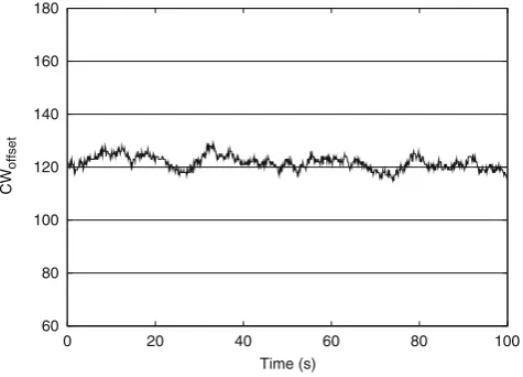
5.2 Stability
One of the objectives of the configuration of the PI controller presented in Section 4.4 is guaranteeing a stable behavior of the system. In order to assess this objective, we plot in Fig.4 the value of the system’s control signal (CWo f f set) every beacon interval, for our
{Kp,Ki}setting with n=20stations. We can observe
that with the proposed setting, CWo f f setperforms stably
with minor deviations around its point of operation. In case that a larger setting for {Kp,Ki}was used to
improve the speed of reaction to changes, we would have the situation of Fig.5. For this case, with values for {Kp,Ki} 20 times larger, the CWo f f set shows a
60 80 100 120 140 160 180
0 20 40 60 80 100
CW
offset
Time (s)
Figure 4 Stable configuration
60 80 100 120 140 160 180
0 20 40 60 80 100
CW
offset
Time (s)
Figure 5 Unstable configuration
strong unstable behavior with drastic oscillations. We conclude that the proposed configuration achieves the objective of guaranteeing a stable behavior.
5.3 Speed of reaction to changes
In addition to a stable behavior, we also require the PI controller to quickly react to changes on the WLAN. To assess this objective we ran the following experi-ment. For a WLAN with 15 saturated stations, at t= 80 we added 15 more stations. We plot the behavior of CWo f f set for our {Kp,Ki} setting in Fig. 6 (label
“Kp,Ki”). The system reacts fast to the changes on
the WLAN, as CWo f f set reaches the new value almost
immediately. We have already shown in the previous section that large values for the parameters of the con-troller lead to unstable behavior. To analyze the impact of small values for these parameters, we plot on the
0 50 100 150 200 250
0 100 200 300 400 500
CW
offset
Time (s)
Kp,Ki Kp/20,Ki/20
same figure the CWo f f setevolution for a{Kp,Ki}setting
20 times smaller (label “Kp/20,Ki/20”). With such setting, although obtaining a minor gain in stability, the system reacts too slow to changes of the conditions on the WLAN.
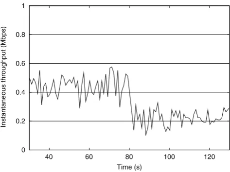
We conclude that, by means of the Ziegler-Nichols rules, we achieve a proper tradeoff between stability and speed of reaction to changes. To further validate this, in Fig.7we illustrate the time plot of the instan-taneous throughput of one station, averaged over 1 s intervals, for the same previous experiment of Fig.6. We can see from the figure that the system is able to provide stations with constant throughput (apart from minor oscillations due to the use of CSMA/CA), reacting almost immediately to changes.
5.4 Non-saturated stations
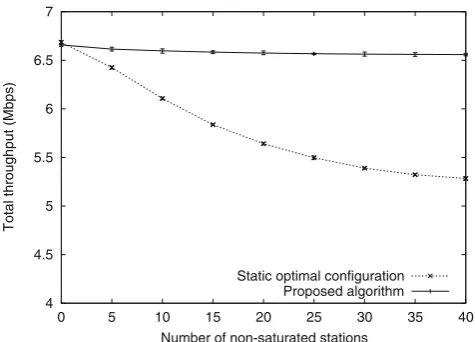
Our approach has been designed to optimize perfor-mance both under saturation and non-saturation con-ditions, in contrast to the static optimal configuration shown previously which is based on the assumption that all stations are saturated. In order to evaluate and compare the performance of the two algorithms when there are non-saturated stations in addition to saturated stations, we performed the following experiment. We had 5 saturated stations and a variable number of non-saturated stations in the WLAN. The non-non-saturated stations generated CBR traffic at rate of 100 Kbps. The total throughput resulting from this experiment is illustrated in Fig. 8. In this figure, we compare the performance of our approach against the static optimal configuration, resulting from computing the configura-tion with Eq.18 and taking as n the total number of
0 0.2 0.4 0.6 0.8 1
40 60 80 100 120
Instantaneous throughput (Mbps)
Time (s)
Figure 7 Instantaneous throughput
4 4.5 5 5.5 6 6.5 7
0 5 10 15 20 25 30 35 40
Total throughput (Mbps)
Number of non-saturated stations Static optimal configuration
Proposed algorithm
Figure 8 Non-saturated stations
stations present in the WLAN, regardless of whether they are saturated or not.
We observe from Fig. 8 that with our approach, the total throughput remains approximately constant with values similar to the ones obtained for saturation conditions (Fig. 3), independently of the number of non-saturated stations. In contrast, the performance of the static optimal configuration decreases very substan-tially as the number of non-saturated stations increases. This is due to the fact that the static optimal configura-tion considers that all staconfigura-tions are continuously sending packets and therefore uses too conservative CW values. From the above results we conclude that our algo-rithm achieves optimal performance also when non-saturated stations are present in the WLAN, in contrast to the static optimal configuration which sees its per-formance severely degraded as the number of non-saturated stations increases.
5.5 Bursty traffic
In order to understand whether bursty traffic can harm the performance of the proposed algorithm, we re-peated the experiment reported in the previous sec-tion but with the non-saturated stasec-tions sending highly bursty traffic instead of CBR. In particular, in our experiment we used ON/OFF sources with exponen-tially distributed active and idle periods of an average duration of 100 ms each. The results of this experiment are depicted in Fig.9.
4 4.5 5 5.5 6 6.5 7
0 5 10 15 20 25 30 35 40
Total throughput (Mbps)
Number of non-saturated stations Static optimal configuration
Proposed algorithm
Figure 9 Bursty traffic
under constant traffic but also under highly variable sources.
5.6 Comparison against other approaches
The Sliding Contention Window (SCW) [14] and the dynamic tuning algorithm of [15] (hereafter referred to as DTA) are, like ours, centralized solutions com-patible with the 802.11e standard that do not require hardware modifications. In this section we compare our solution against these centralized mechanisms.
Figure10gives the total throughput performance of the different solutions for varying numbers of stations. We observe that the proposed algorithm outperforms significantly both SCW and DTA. The reason is that our algorithm is sustained on the analysis of Section3, which guarantees optimized performance, in contrast to SCW and DTA which are based on heuristics. In
1 2 3 4 5 6 7 8
5 10 15 20 25 30 35 40
Total throughput (Mbps)
Number of stations
SCW DTA Proposed algorithm
Figure 10 Comparison against other approaches
particular, SCW uses an algorithm to adjust CWmin
that chooses overly large values, thereby degrading the performance. On the other hand, DTA sets the CWmin
value as an heuristic function of the number of stations yielding overly small values, which results in a degraded performance also for this case.
5.7 Impact of channel errors
Most of the adaptive mechanisms proposed for IEEE 802.11 WLANs do not consider the impact of channel errors [4–15]. However, channel errors may influence these mechanisms since they are wrongly interpreted as collisions, leading to an unnecessary increase of the contention window and therefore to a suboptimal configuration.
In order to asses the impact of channel errors upon our approach we performed the following experiment. We varied the frame error rate (FER) from 0% to 10% for a scenario with n=20active stations in the WLAN. We compared the performance of our proposal against the static optimal configuration, which does not change the configuration upon failed transmissions and there-fore uses always the optimal contention window value. The results of this experiment are illustrated in Fig.11. We observe that for a realistic range of error probabili-ties (from 0% to 5%) the impact on throughput perfor-mance is negligible. Moreover, even for very large error rates (up to 10%) the performance loss is very small. Note that current WLANs use link adaptation mecha-nisms which guarantee small error rates by choosing a more robust modulation scheme upon detecting quality variations of the wireless channel [23]. We conclude that with the proposed scheme errors have a minimal impact on the performance.
1 2 3 4 5 6 7 8
0 2 4 6 8 10
Total throughput (Mbps)
FER (%)
Static optimal configuration Proposed algorithm
6 Conclusions
In this paper we have proposed a novel adaptive al-gorithm for optimizing the performance of a WLAN. The algorithm is sustained on the observation that the collision probability in an optimally configured WLAN is approximately constant, independent of the number of stations. Our proposal only requires to measure this collision probability by monitoring successfully trans-mitted frames during an inter-beacon period at the AP. Our algorithm is based on a well established troller from discrete-time control theory, the PI con-troller. By means of a theoretical analysis of the WLAN and the controller, we have designed our algorithm to maximize the throughput performance. We achieve a proper tradeoff between stability and speed of reaction to changes by applying the Ziegler-Nichols rules. We have shown via simulations that our algorithm drives the WLAN to the optimal point of operation, even for non-saturated and highly bursty traffic, reacting quickly to changes of the conditions in the WLAN.
As opposed to most of the previous proposals, our algorithm is fully compatible with the 802.11e EDCA standard and does not require any modifications nei-ther at a hardware nor at a driver level. We have shown that our proposal substantially outperforms other cen-tralized 802.11e-compatible solutions.
Acknowledgements The work described in this article has
been partially supported by the European Community’s Seventh Framework Programme under the ICT FP7 Integrated Project CARMEN (INFSO-ICT-214994) and by the Spanish Gov-ernment under the POSEIDON project (TSI2006-12507-C03). Apart from this, the European Commission and the Spanish Government have no responsibility for the content of this paper. The authors would like to thank the reviewers for their valuable comments which helped improving this paper.
Appendix
Theorem 1 The system is stable with the proposed Kp
and Kiconfiguration.
Proof The closed-loop transfer function of our system
is
S(z)= −C(z)H(z)
1−C(z)H(z)=
= −z(z−1)H Kp−zH Ki
z2+(−H K
p−1)z+H(Kp−Ki)
(44)
where
H = −τopt popt
1+popt
m−1
i=0 (2popt)i
2 (45)
A sufficient condition for stability is that the poles of the above polynomial fall within the unit circle|z|<1. This can be ensured by choosing coefficients{a1,a2}of
the characteristic polynomial that belong to the stability triangle [24]:
a2<1 (46)
a1<a2+1 (47)
a1>−1−a2 (48)
In the transfer function of Eq.44the coefficients of the characteristic polynomial are
a1= −H Kp−1 (49)
a2=H
Kp−Ki
(50)
From Eqs.42and45we have
H Kp= −0.4τ opt
popt
(51)
and from Eqs.43and45we have
H Ki= −
0.4 0.85·2
τopt
popt
(52)
from which
a1=0.4τ
opt
popt−
1 (53)
a2= −0.16τ
opt
popt
(54)
Givenτopt≤ popt, it can be easily seen that the above
{a1,a2}satisfy the conditions of Eqs.46,47and48. The
proof follows.
References
1. IEEE 802.11 WG (1999) Information technology - telecom-mun. and information exchange between systems. Local and Metropolitan area networks. Specific requirements. Part 11: wireless LAN medium access control (MAC) and phys-ical layer (PHY) specifications, Standard, August. IEEE, Piscataway
3. Banchs A, Pérez-Costa X, Qiao D (2003) Providing through-put guarantees in IEEE 802.11e wireless LANs. In: Proceed-ings of the 18th international teletraffic congress (ITC18), Berlin, September 2003
4. Yang Y, Wang JJ, Kravets R (2007) Distributed optimal contention window control for elastic traffic in single-cell wireless LANs. IEEE/ACM Trans Netw 15(6):1373–1386, December
5. Bianchi G, Fratta LL, Oliveri M (1996) Performance eval-uation and enhancement of the CSMA/CA MAC protocol for 802.11 wireless LANs. In: Proceedings of the seventh IEEE international symposium on personal, indoor and mobile radio communications (PIMRC96), Taipei, October 1996
6. Xia Q, Hamdi M (2006) Contention window adjustment for IEEE 802.11 WLANs: a control-theoretic approach. In: Proceedings of IEEE ICC 2006, Istanbul, June 2006 7. Ni Q, Aad I, Barakat C, Turletti T (2003) Modeling and
analysis of slow CW decrease for IEEE 802.1 1 WLAN. In: Proceedings of the seventh IEEE international sympo-sium on personal, indoor and mobile radio communications (PIMRC 2003), Beijing, September 2003
8. Pang Q, Liew SC, Lee JYB, Leung VCM (2004) Performance evaluation of an adaptive backoff scheme for WLAN. Wirel Commun Mob Comput 4(8):867–879, December
9. Song N-O, Kwak B-J, Song J, Miller ME (2003) Enhance-ment of IEEE 802.11 distributed coordination function with exponential increase exponential decrease backoff algorithm. In: Proceedings of the 57th IEEE semiannual vehicular tech-nology conference (VTC 2003-Spring), Jeju, April 2003 10. Banchs A, Perez X (2006) Distributed fair queuing in IEEE
802.11 wireless LAN. In: Proceedings of IEEE ICC 2002, New York, April 2006
11. Heusse M, Rousseau F, Guillier R, Duda A (2005) Idle sense: an optimal access method for high throughput and fairness in rate diverse wireless lans. In: SIGCOMM ’05: Proceedings of the 2005 conference on applications, technologies, archi-tectures, and protocols for computer communications. ACM, New York, pp. 121–132
12. Calì F, Conti M, Gregori E (2000) Dynamic tuning of the ieee 802.11 protocol to achieve a theoretical throughput limit. IEEE/ACM Trans Netw 8(6):785–799
13. Bononi L, Conti M, Gregori E (2004) Runtime optimization of ieee 802.11 wireless lans performance. IEEE Trans Parallel Distrib Syst 15(1):66–80
14. Nafaa A, Ksentini A, Ahmed Mehaoua A, Ishibashi B, Iraqi Y, Boutaba R (2005) Sliding contention window (SCW): towards backoff range-based service differentiation over IEEE 802.11 wireless LAN networks. IEEE Network 19(4):45–51, July
15. Freitag J, da Fonseca NLS, de Rezende JF (2006) Tuning of 802.11e network parameters. IEEE Commun Lett 10(8):611–613, August
16. IEEE 802.11 WG (2005) Amendment to standard for infor-mation technology. LAN/MAN specific requirements - part 11: wireless LAN medium access control (MAC) and physical layer (PHY) specifications: medium access control (MAC) enhancements for quality of service (QoS), Supplement to IEEE 802.11 standard, November
17. IEEE 802.11 WG (2006) Information technology - telecom-munications and information exchange between systems. Local and Metropolitan area networks. Specific require-ments. Part 11: wireless LAN medium access control (MAC) and physical layer (PHY) specifications, IEEE 802.11-REVma/D9.0, Revision of Std. 802.11–1999
18. Banchs A, Vollero L (2006) Throughput analysis and optimal configuration of 802.11e EDCA. Comput Networks 50(11): 1749–1768, August
19. Hollot CV, Misra V, Towsley D, Gong W-B (2001) A con-trol theoretic analysis of RED. In: Proceedings of IEEE INFOCOM 2001, Anchorage, April 2001
20. Franklin GF, Powell JD, Workman ML (1990) Digital control of dynamic systems, 2nd edn. Addison-Wesley, Reading 21. Banchs A, Serrano P, Oliver H (2007) Proportional fair
throughput allocation in multirate 802.11e EDCA wireless LANs. Wirel Netw 13(5), October
22. IEEE 802.11 WG (1999) Information technology - telecom-mun. and information exchange between systems. Local and Metropolitan area networks. Specific requirements. Part 11: wireless LAN medium access control (MAC) and physi-cal layer (PHY) specifications: high-speed physiphysi-cal layer ex-tension in the 2.4 GHz band, Supplement to IEEE 802.11 standard, September
23. Aguiar A, Wolisz A (2007) Channel prediction heuristics for adaptive modulation in WLAN. IEEE 65th Vehicular Technology Conference, 2007. VTC2007-Spring, April 2007, Dublin