International Journal of Emerging Technology and Advanced Engineering
Website: www.ijetae.com (ISSN 2250-2459, Volume 2, Issue 4, April 2012)676
Simple And Efficient Implementation Of Two-Phase
Interleaved Boost Converter For Renewable Energy Source
Mounica Ganta
1, Pallam reddy Nirupa
2, Thimmadi Akshitha
3, Dr.R.Seyezhai
41,2,3 Student, Department of EEE, SSN College of Engineering, Chennai, India 4Associate Professor, Department of EEE, SSN College of Engineering, Chennai, India
1[email protected], 2[email protected], 3
[email protected], [email protected]
Abstract--- DC-DC Boost Converters serves many purposes and usually required in many applications which has a low output voltage for renewable energy sources such as Fuel cells, Batteries, Photo-voltaic cells. Interleaved Boost converter (IBC) has better performance characteristics when compared to a conventional boost converter due to its increased efficiency, reduction in size and greater reliability. IBC consists of a number of boost converters connected in parallel and controlled by the interleaved method which has the same switching frequency and phase shift. This paper focuses on the design aspects of two phase interleaved boost converter. The various parameters of the IBC are compared to a conventional boost converter. Simulation studies have been carried out using MATLAB/SIMULINK. Theoretical analysis is done to emphasis the benefits of the interleaved boost converter.
Key words--- IBC , MATLAB , ripple and efficiency.
I. INTRODUCTION
Most renewable sources energy sources such as fuel cells and photovoltaic cells have received a worldwide great attention in research fields, there is renewed focus on the power electronic converter interface for DC energy sources. These power sources have quite low -voltage output and require series connection of voltage booster to provide enough voltage output. DC-DC boost converter is generally used to further boost the voltage to the required level. Various other boosters such as boost, buck-boost series resonant full-bridge and push-pull converters are not recommended because they add objectionable ripples in the current flowing out of the fuel cell. To minimize the ripples, an IBC has been proposed as a suitable interface for this renewable source [1]. Two-phase boost converter operates at a very large duty cycle due to a high output voltage and a low input voltage. Interleaved method is used to improve converter performance in terms of efficiency, size, conducted electromagnetic emission and transient response. To minimize the amount of ripples, IBC has been proposed in addition to which it has improved performance characteristics of higher power capability, modularity and improved reliability [2].
However IBC improves converter performance at the cost of additional inductors, switching devices and output rectifiers. Mathematical analysis of the current ripple and the design parameters included in this study. Simulation study has been performed to understand the efficiency of the IBC and the results have been validated.
The parallel connection of boost converters in high-power applications is a well-known technique. Its main advantage stems from the fact that sharing the input current among the parallel converters allows smoothing some of the design constraints of the switching cells. It also has an added advantage that the switching and conduction losses are less in interleaved boost converter than the conventional boost converter. The cancellation of low frequency harmonics eventually allows the reduction in size and losses of the filtering stages. Simulation results show that the current ripple in the input and output circuits is less and also minimizes the size of input filter and output power is more for IBC[3]. The frequency of the current ripple is twice for two phase IBC than the conventional boost converter. Due to a phase shift of 180 degrees ripple cancellation takes place. This paper concentrates on the various design aspects, steady state and transient response, device selection, operating principle, gating pattern and the various waveforms which compares with the conventional boost converter.
II. OPERATION PRINCIPLE OF INTERLEEAVED
BOOSTCONVERTER
International Journal of Emerging Technology and Advanced Engineering
Website: www.ijetae.com (ISSN 2250-2459, Volume 2, Issue 4, April 2012)677
In the DCM, the difficulties of the reverse recovery effects are taken care but it leads to high input current and conduction losses and it is not best suited for high power applications. CCM has lower input peak current, less conduction losses and can be used for high power applications. By dividing the output current into ‘n’ paths higher efficiency is achieved and eventually reducing the copper losses and the inductor losses.
Here the operation of two phase interleaved boost converter is explained which is shown in the figure. Firstly when the device S1 is turned ON, the current in the inductor iL1 increases linearly. During this period energy is stored in the inductor L1. When S1 is turned OFF, diode D1 conducts and the stored energy in the inductor ramps down with a slope based on the difference between the input and output voltage. The inductor starts to discharge and transfer the current via the diode to the load. After a half switching cycle of S1, S2 is also turned ON completing the same cycle of events. Since both the power channels are combined at the output capacitor, the effective ripple frequency is twice than that of a single-phase boost converter. The amplitude of the input current ripple is small. This advantage makes this topology very attractive for the renewable sources of energy.
The gating pulses of the two devices are shifted by a phase difference of 360/n, where n is the number of parallel boost converters connected in parallel. For a two-phase interleaved boost converter n=2, which is 180 degrees and it is shown in Fig.2.
In the figure 1 it can be seen that the input current, i, for two phase interleaved boost converter is the sum of each channels inductors currents. As the two devices are phase-shifted by 180 degrees, the input current ripple produced is the smallest.
Fig.1. Circuit diagram of two-phase IBC
Fig.2.Switching pattern of 2-phase IBC
III. DESIGN ASPECTS OF IBC
The design aspects of IBC are discussed in this section:
1. Boost ratio:
The boosting ratio of the converter is a function of the duty ratio. It is same as in conventional boost converter. It is defined as
(1) Where is the output voltage, is the input voltage and D is the duty ratio.
2. Input current
The input current can be calculated by the input power and the input voltage.
(2) Where is the input power, is the input voltage.
3. Inductor current ripple peak-to-peak amplitude
The inductor current ripple peak-peak amplitude is given by
International Journal of Emerging Technology and Advanced Engineering
Website: www.ijetae.com (ISSN 2250-2459, Volume 2, Issue 4, April 2012)678
Where is the switching frequency, D is the duty cycle, is the input voltage and L is the inductance.
4. Relationship between input current ripple peak-to-peak amplitude and inductor current ripple peak-to-peak amplitude
Mostly in IBC the minimum input ripple occurs at a duty ratio of 0.5, this is due to the 180 degrees phase difference between the two devices[5]. There are two operating modes which can be defined by the inductor:
(i) Mode 1, D>0.5: over a particular period of time the current in both the inductors rises. (ii) Mode2, D<0.5: over a specified period of
time both the inductors discharge
Hence the input current ripple peak-to –peak amplitude is given by [6],
(4)
The design of IBC involves selection of inductor, output capacitor, number of phases, device selection and the freewheeling diodes. The inductors and diodes have to be same in all the parallel paths of an IBC.
A. Selection of inductor and capacitor:
Now-a-days in the power electronic systems the magnetic components play a major role for energy storage and filtering. As discussed in the operation of IBC the inductor is used to transform the energy from the input voltage to the inductor current and to convert it back from the inductor current to the output voltage. As per the principle the two inductors shown in the Fig.1. are identical in order to balance the current in the two boost converters.
The value of the inductor can be found out by the following formulae [7]:
(5) Where Vs represents the source voltage and ∆ represents the inductor current ripple, D represents the duty ratio. The value of the capacitor is given by the formulae
(6)
Where Vo represents the output voltage (V), D represents the duty ratio, F represents the frequency, R represents the resistance and ∆Vo represents the change in the output voltage (V).
B. Choosing the number of phases:
The factor which decides in choosing the number of phases is that the ripple content reduces with the increases in the number of phases. In a two phase IBC ripple reduces to 9% of that of a conventional boost converter. There is a restriction to the increase in number of phases because if the number of phases is increased further without much reduction in ripple content the size of the components increases and hence increases the cost of performance. Therefore the number of phases is chosen to be two. It is to be noted that the number of inductors, switches and diodes are same as the number of phases and the switching frequency should be same for all the phases [8].
C. Duty ratio:
The duty ratio selection is based on the number of phases; the ripple is minimum at a certain duty ratio. In the two phase interleaved boost converter ripple is minimum at duty ratio in the range of 0.45.
D. Selection of the devices:
The device which is chosen for the interleaved boost converter is power MOSFET because of its high commutation speed and high efficiency at low voltages [9]. It shares with the IGBT an isolated gate that makes it easy to drive.
IV. SIMULATION RESULTS
Using MATLAB the simulation of interleaved boost converter is performed. The waveforms of the output voltage ripple , input current ripple is shown and also the comparison of conventional boost converter with IBC is shown in the form of waveforms as below. The value of the inductor and the capacitor, and also the gating pattern are designed as discussed above.
International Journal of Emerging Technology and Advanced Engineering
Website: www.ijetae.com (ISSN 2250-2459, Volume 2, Issue 4, April 2012)679
TABLE1: SIMULATION PARAMETERS OF IBC
The above results are for a duty cycle of 0.5. Varying the duty cycle the input current ripple and output voltage ripple varies as follows. The different values are tabulated and the graphs are drawn to examine the variations. From the simulation results, the waveforms of the interleaved boost converter and the conventional boost converter have been shown in Figs.3,4, 5, 6 &7. The difference between the two is well understood by observing the simulated waveforms. The transient and the steady state response of IBC is shown in Fig.3.
Fig.3.Transient and steady state response of IBC
The output voltage ripple, input current ripple and output current ripple waveforms of IBC has been shown in Figs.4,5 and Fig.6.
Fig.4.Output voltage ripple of IBC
Fig.5. Input current ripple of IBC
Fig.6. Output current ripple of IBC
PARAMETERS VALUES
Input Voltage 5v
Output Voltage 9.0183V
Switching
Frequency 25kHz
Duty Ratio
0.5 Inductance
0.015mH Capacitance
0.22mF Efficiency
International Journal of Emerging Technology and Advanced Engineering
Website: www.ijetae.com (ISSN 2250-2459, Volume 2, Issue 4, April 2012)680
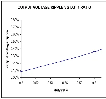
[image:5.612.351.532.115.284.2]The output voltage ripple and input current ripple of boost converter has been shown in Fig.7. and Fig.8.
[image:5.612.51.302.148.282.2]Fig.7.Output voltage ripple of Boost converter
Fig.8. Input current ripple of boost converter
A tabulation is shown in table II which gives the input current ripple of IBC at different duty ratios.
TABLE II: VARIATION OF INPUT CURRENT RIPPLE AT DIFFERENT DUTY RATIOS
Fig.9. shows percentage of output voltage ripple versus different duty ratios. It is observed that there is a linear relationship between the two quantities.
OUTPUT VOLTAGE RIPPLE VS DUTY RATIO
0.00% 0.10% 0.20% 0.30% 0.40% 0.50% 0.60% 0.70% 0.80%
0.5 0.52 0.54 0.56 0.58 0.6
duty ratio
o
u
tp
u
t
v
o
lt
a
g
e
r
ip
p
le
Fig.9. Output voltage ripple vs duty ratio
Fig.10.shows a graph between efficiency and various percentages of load. The values are tabulated as below. Results show that efficiency increases as the load increases.
Efficiency vs % of load
74 76 78 80 82 84 86 88 90 92
0 20 40 60 80 100
% OF LOAD
E
F
F
IC
IE
N
C
[image:5.612.56.275.325.469.2]Y
Fig.10. Efficiency vs load curve
TABLE III shows the comparison between conventional boost converter and IBC.
TABLE III: COMPARISON BETWEEN CONVENTIONAL BOOST CONVERTER AND IBC
PARAMETERS BOOST
CONVERTER
INTERLEAVED BOOST CONVERTER
Input Voltage 5V 5V
Output Voltage 8.918V 9.0183V
Switching Frequency 25Khz 25Khz
Input Current Ripple 17.2% 0.0276%
Output Ripple Voltage 1.81% 0.08%
Output Current Ripple 1.81% 0.077%
Frequrncy Of Ripple Current
25kHz 50kHz
Efficiency 88.155% 90%
DUTY RATIO INPUT CURRENT RIPPLE
0.45 3.8%
0.5 0.0276%
0.6 3.859%
[image:5.612.326.561.357.519.2]International Journal of Emerging Technology and Advanced Engineering
Website: www.ijetae.com (ISSN 2250-2459, Volume 2, Issue 4, April 2012)681
V. CONCLUSION
The above paper has discussed the principle and operation of interleaved boost converter and the various design parameters have been presented. The various waveforms of IBC as well as the conventional boost converter have been simulated using MATLAB SIMULINK. Using these results, the comparison between interleaved boost converter and the conventional boost converter has been done using MATLAB. The advantages of IBC having higher efficiency and reduced ripple content can be well understood from the simulation results. Also, the relationship between input current ripple at various duty ratios and efficiency versus load has been discussed.
REFERENCES
[1] Geoffrey R. Walker, Paul C. Sernia, 2004. Cascaded DC-DC Converter Connection of Photovoltaic Modules”. IEEE Trans. on power electronics,vol.19,no.4.
[2] Gyu-Yeong Choe, Hyun-Soo Kang, Byoung-Kuk Lee and Won-Yong Lee, 2007. Design Consideration of Interleaved Converters for Fuel Cell Applications, in Proceedings of International Conference on Electrical Machines and Systems ,Seoul, Korea, pp.238-243.
[3] P.A.Dahono, S.Riyadi , A.Mudawari and Y.Haroen,. 1999. Output ripple analysis of multiphase DC–DC converter‘‘. IEEE Int. Conf. Power Electrical and Drive Systems, Hong Kong, pp. 626–631.
[4] L. Huber, B. T. Irving, M. M. Jovanovic. 2008. Open-loop control methods for interleaved DCM/CCM boundary boost PFC converters,IEEE Trans. Power Electron., vol. 23, no. 4, pp.1649 – 1657.
[5] P.Thounthong, P.Sethakul, S.Rael and B.Davat 2008. Design and implementation of 2- phase interleaved boost converter for fuel cell power source,‘ Int. Conf. Power Electronics, Machines, and Drives,PEMD 2008, pp. 91–95.
[6] P.Lee, Y.Lee, D.K.W. Cheng and X.Liu. 2000. Steady-state analysis of an interleaved boost converter with coupled inductors‘. IEEE Trans. Industrial Electronics, pp. 787–795 .
[7] R. Seyezhai and B.L.Mathur . 2011. Design and implementation of fuel cell based Interleaved Boost Converter’, International Conference on Renewable Energy , ICRE 2011 Jan 17-21, 2011, University of Rajasthan, Jaipur.
[8]H. B. Shin, J. G. Park, S. K. Chung, H. W. Lee and T. A. Lipo (2005) ‘Generalised steady-state analysis of multiphase interleaved boost converter with coupled inductors’, IEE Electr. Power Appl, Vol.152, Issue.3, pp.584 - 594.
[9] MOSFET Basics By K.S.Oh. FAIRCHILD Semiconductors, July 2000.