Gregory Smyth PhD 1*, Philip M Evans DPhil 2,3, Jeffrey C Bamber PhD 1
and James L Bedford PhD 1
1 Joint Department of Physics at The Institute of Cancer Research and The Royal Marsden
NHS Foundation Trust, London, UK
2 Centre for Vision, Speech and Signal Processing, University of Surrey, Guildford, UK
3 National Physical Laboratory, Hampton Road, Teddington, Middlesex, UK
Review article
Running title: Recent developments in non-coplanar radiotherapy
* Corresponding author: Gregory Smyth, Joint Department of Physics at The Institute of
Cancer Research and The Royal Marsden NHS Foundation Trust, Downs Road, Sutton, London, SM2 5PT, United Kingdom. Email: [email protected] Tel: +44 20 8661 3472 Fax: +44 20 8643 3812
Abstract
This paper gives an overview of recent developments in non-coplanar intensity modulated
radiotherapy (IMRT) and volumetric modulated arc therapy (VMAT). Modern linear
accelerators are capable of automating motion around multiple axes, allowing efficient
delivery of highly non-coplanar radiotherapy techniques. Novel techniques developed for
C-arm and non-standard linac geometries, methods of optimization, and clinical applications are
reviewed. The additional degrees of freedom are shown to increase the therapeutic ratio,
either through dose escalation to the target or dose reduction to functionally important organs
at risk, by multiple research groups. Although significant work is still needed to translate
these new non-coplanar radiotherapy techniques into the clinic, clinical implementation
should be prioritised. Recent developments in non-coplanar radiotherapy demonstrate that it
Introduction
Non-coplanar radiotherapy uses a number of fixed or rotating radiation beams that do not
share the same geometric plane relative to the patient [1]. This reduces the beam overlap
away from the tumour. Conventional C-arm linear accelerators (linacs) achieve this by
rotating the recumbent patient around the isocentre on a treatment couch to a different
position for each beam orientation [1]. Non-coplanar radiotherapy is more common in
intracranial stereotactic radiotherapy, single-fraction radiosurgery (SRS, Table 1) and
stereotactic body radiotherapy (SBRT) [1]. These techniques often deliver higher fractional
doses and require highly conformal, sharp dose gradients outside the planning target volume
(PTV) to minimize dose to adjacent normal tissue [2]. Non-coplanar beams are also used in
accelerated partial breast irradiation (APBI) to spare the ipsilateral breast [3], which may
improve cosmetic outcomes [4]. In head and neck cancer non-coplanar radiotherapy reduces
the low and intermediate dose bath [5], which may decrease the incidence of neurocognitive
side effects and fatigue [6, 7].
The need for manual intervention to rotate the patient couch makes non-coplanar
radiotherapy time-consuming when using C-arm linacs. The adoption of volumetric
modulated arc therapy (VMAT), an efficient rotational intensity modulated radiotherapy
(IMRT) delivery technique [8-11], also makes non-coplanar beam arrangements less
appealing in practice. However, recently there has been renewed interest in non-coplanar
radiotherapy, as modern linacs allow automated motion of multiple rotation axes [12].
This review aims to give an overview of recent developments in non-coplanar radiotherapy.
have been developed (Table 2) and what sites might benefit from their use? (2) What
technological and computational approaches are required for treatment planning and
delivery? (3) What issues must be resolved prior to the clinical implementation of new
non-coplanar radiotherapy techniques?
Recent developments in non-coplanar IMRT
Non-coplanar IMRT for C-arm linacs
Non-coplanar IMRT (NC-IMRT) has been generally limited to a small number of beam
orientations due to the increased delivery time required. However, with modern automated
delivery, the use of NC-IMRT with 20 or more beams may now be practical [12]. Research
in this area is led by a group at the University of California, Los Angeles (UCLA).
The group’s initial work has focused on SBRT for liver [13] and lung [14] tumours, where
dose escalation is technically challenging due to the proximity of critical organs. In both
cases, organ at risk (OAR) constraints prevent dose escalation for complex cases, or require
compromises in tumour dose to avoid unacceptable risk of toxicity. For liver SBRT, fourteen
and 22-beam NC-IMRT plans are compared with coplanar VMAT and are found to reduce
normal liver dose [13]. For lung SBRT, 30-beam NC-IMRT is compared with VMAT and
enables dose escalation to the tumour by an additional 20 Gy while conventional OAR dose
constraints are still met [14]. Alternatively, OAR doses can be reduced while delivering the
conventional prescription dose to the tumour.
Subsequent work has investigated other sites where dose escalation is thought likely to be
glioblastoma, critical structures such as the brainstem often abut or overlap the PTV, which
limits the prescription dose to 60 Gy. Nguyen et al. investigate the potential of dose
escalation of the PTV, the GTV alone, and treating an expanded PTV using 30-beam
NC-IMRT [15]. Although dose escalation up to 100 Gy is feasible, using such a high prescription
in practice is questionable due to the increased risk of brain necrosis above 60 Gy [17]. Dose
escalation for SBRT in head and neck cancer patients by up to 20 Gy is also technically
possible using 30-beam NC-IMRT [16]. However, in practice, care is required when the
tumour lies close to critical structures, in this case the carotid artery.
These studies provide the initial evidence that by employing a large number of beams,
NC-IMRT produces highly conformal dose distributions that can further reduce OAR doses,
dose-escalate the tumour while observing OAR dose constraints, or make treatment of
challenging body sites practical. Additional treatment planning studies by this group
investigate NC-IMRT for cancers of the prostate [18, 19], liver [20], and brain [21].
NC-IMRT has been clinically implemented within a prospective Phase 1 trial for patients
requiring retreatment of primary brain tumours [22]. Patients who have been previously
treated to 59.4 Gy or 60 Gy receive a further 25 or 30 Gy in 5 or 10 fractions. Plans using
13-20 beams (median = 16) are compared with static couch non-coplanar VMAT. Plans are
judged on the basis of PTV coverage and OAR sparing, and the preferred plan is treated. Of
the ten patients in the study whose plans meet acceptable OAR tolerances, nine have been
treated with NC-IMRT and one patient has been treated with a VMAT plan of equivalent
quality. The NC-IMRT beam orientation search space and the beam arrangement for an
Optimization techniques for non-coplanar IMRT
Determining the optimal set of beam orientations for a clinical case is challenging. As plan
quality does not vary smoothly with changes in beam orientation, the solution space is likely
to contain local optima [23]. Many groups have investigated beam orientation optimization
(BOO) for IMRT, and the literature has been extensively reviewed previously [24, 25]. Only
the application of these BOO methods to new non-coplanar radiotherapy techniques is
covered in this paper.
NC-IMRT work that has been reported by the UCLA group uses an iterative approach to
BOO [13]. Iterative BOO uses fluence optimization to evaluate plan quality during BOO
[26] and has been applied to a wide range of clinical cases by the ERASMUS group in
Rotterdam [27-35]. Although fluence optimization does not account for the effects of
practical machine delivery constraints present in a clinical treatment plan, the idealised dose
distribution it produces can give a useful estimate of plan quality. New orientations are
added to a beam arrangement until either the maximum permitted number of beams is
reached, or the effect of adding another beam no longer significantly improves the
optimization objective function. However, the scheme is slow to converge [36] and can be
trapped in a local minimum by the first beam chosen [27].
In the UCLA implementation of iterative BOO, at each iteration the beam orientation that
most reduces the objective function is added. The objective function improvement for each
potential beam is estimated using a single iteration of fluence optimization, which results in a
more efficient search [13].
Non-coplanar VMAT for C-arm mounted linacs
Several papers have proposed methods of non-coplanar VMAT treatment delivery. These
break down into three areas: (1) VMAT with multiple static couch rotations, (2) a coronal
VMAT technique that combines dynamic couch rotation with fixed gantry positions, and (3)
a trajectory VMAT technique that combines dynamic couch rotation with dynamic gantry
rotation. Feasible orientations for non-coplanar VMAT, as well as a range of other
techniques, are shown in Figure 2.
Static couch non-coplanar VMAT
The simplest application of non-coplanar radiotherapy to VMAT uses one or more arcs with
static couch rotations. Although it has been investigated for sites such as sinus cancer [37],
liver [38], and head and neck [34, 39], it is commonly used for intracranial stereotactic
radiotherapy and SRS [40, 41].
Four-arc static couch non-coplanar VMAT (SCNC-VMAT) improves conformity and
reduces the volume of brain receiving intermediate doses in twelve single-lesion SRS cases,
when compared with coplanar VMAT and nine-field NC-IMRT [40]. However, the best
technique for sparing OARs close to the PTV depends on the patient’s specific geometry. An
alternative SCNC-VMAT technique, which combines three non-coplanar arcs and one
coplanar arc, has been evaluated for up to nine lesions [41, 42]. This class solution has since
been incorporated into the Eclipse (Varian Medical Systems, Palo Alto, CA) treatment
HyperArc combines SCNC-VMAT with standardised immobilisation devices, to prevent
collisions, and automated transitions between each partial arc during treatment, to improve
delivery efficiency. HyperArc reduces dose to normal brain tissue when compared against
VMAT for 23 SRS cases, with up to four lesions each [44]. However, beams are more
complex and require more monitor units due to increased modulation. Another study of
fifteen SRS cases, with between three and eight lesions each, does not find significant
differences between HyperArc, CyberKnife (Accuray Inc, Sunnyvale, CA) and VMAT for
most OAR criteria studied [43]. Differences in homogeneity and the volume of tissue
receiving 110% of the prescription dose are significant between HyperArc and CyberKnife
but this may be due to different planning approaches across software.
Coronal VMAT
Dynamic couch rotation with fixed lateral gantry positions, to achieve a coronal VMAT
technique, has been proposed for APBI [45]. Treatment planning for this site aims to deliver
a homogeneous dose to the partial breast PTV, while minimizing the dose to other OARs,
including the heart, lungs, and contralateral breast. When coronal VMAT is combined with
up to 20◦ of manually-defined gantry rotation, ipsilateral lung dose is reduced at the expense of increased ipsilateral breast dose in patients with inner and central tumours compared with
coplanar VMAT [46].
Coronal VMAT has been refined for prone patient orientations (Figure 3), using lateral couch
translations to avoid collisions between the linac gantry and patient couch [47, 48]. This
produces a discontinuous, non-isocentric beam trajectory. Coronal VMAT improves
conformity and reduces the volume of the ipsilateral normal breast receiving high and
volume of low dose (V20%) increases [48]. However, patients with unfavourable PTV
locations have been excluded from the study, suggesting that coronal VMAT has limitations
for specific geometries.
Trajectory VMAT
Combining dynamic couch rotation with conventional gantry rotation to produce a trajectory
VMAT technique may be more promising than coronal VMAT due to the additional degree
of freedom. Originally proposed for brain and head and neck cancers [49, 50], several groups
have demonstrated the use of different patient-specific trajectory VMAT techniques for OAR
sparing. These include: multiple partial arcs [51], trajectories approximated by
SCNC-VMAT [52], multiple partial arc rotations of the gantry for a single continuous couch rotation
[53], a single continuous rotation of the gantry with synchronised couch rotation [54, 55], or
a single continuous rotation of the couch with synchronised gantry rotation [56].
Due to the additional non-collisional space superiorly, compared with other treatment sites,
brain cancer is commonly investigated. Trajectory VMAT shows significant OAR sparing
compared to coplanar VMAT for multiple optimization techniques [51, 52, 54-58]. OAR
sparing results depend on the inputs to the trajectory and plan optimization, however it is
possible to produce clinically significant sparing for structures such as the contralateral
hippocampus and temporal lobe [55].
Other sites that have been investigated include: head and neck [39], lung [56, 57], prostate
[54, 56], and liver [58]. However, small numbers of cases are used to validate individual
dosimetric improvements for these sites are present over patient populations and are
clinically significant.
Optimization techniques for non-coplanar VMAT
Manual and algorithmic methods
Manual trajectory definition is used in the earliest work on non-coplanar arc techniques,
where beam overlap within the patient from different arc sectors is minimised [49]. At that
time, linac modifications had been required to enable the continuous dynamic couch rotation,
so it has not been widely used [53]. This approach has been revisited recently, using a
manually defined sinusoidal pattern with up to nine partial gantry rotations [53]. Although
this form of trajectory VMAT improves conformity over simpler non-coplanar conformal
arcs, it is dosimetrically equivalent to SCNC-VMAT.
Trajectory definition is also used for coronal VMAT, with an algorithm that maximises couch
rotation while ensuring the PTV lies within the limits of the beam’s eye view [47, 48].
Collisions between linac components are avoided by a combination of modelling and lateral
couch translations. Once the trajectory is determined, VMAT optimization is performed to
define the final beam apertures.
The common factor for manual and algorithmic techniques is that there is no direct method of
trajectory optimization. However, these relatively simple methods to avoid OARs or to
smear out the low dose within the patient have been shown to improve dosimetry for specific
Beam scoring methods
Beam scoring methods, which evaluate a quality metric for each feasible beam orientation,
are frequently used for IMRT beam orientation optimization (BOO). Their advantage is
speed, as scoring a single beam orientation is fast and the many separate evaluations needed
can be performed in parallel [59]. Most beam scoring techniques separate BOO from
treatment plan optimization, which further reduces complexity. However, evaluating beams
independently may not identify a beam arrangement that produces the optimal treatment plan.
Trajectory optimization employing beam scoring generally uses the patient’s geometry to
determine individual beam scores, either projecting it onto the beam’s eye view plane [51,
52] or after ray tracing [54, 55]. Beam scoring has been refined to reflect the relative clinical
importance of OARs [52, 55], OAR position relative to the PTV [52, 60], and to incorporate
dosimetric information for individual voxels [59]. After each feasible beam orientation has
been scored, the trajectory is determined from high-quality orientations. Published
techniques include: grouping promising orientations into partial arcs [51], reducing the path
to a series of fixed couch positions [52], and determining a single connected trajectory
[54-56, 60]. This last approach casts trajectory optimization as a path-finding problem, which is
solved using graph-search techniques such as the Dijkstra [54-56] or A* [58, 60] algorithms.
However, the result also depends on the rules permitted for trajectory formation and this
approach would not find any higher quality multiple partial-arc trajectories.
Fluence-based methods
Although beam scoring produces high quality treatment plans, the final trajectories may not
optimization. An alternative approach incorporates fluence optimization into trajectory
optimization, as a measure of plan quality.
Fluence-based BOO techniques have been applied to trajectory optimization by initially
solving a static field IMRT BOO problem and using the resulting beam orientations to define
a limited number of angular positions that must be visited during delivery [39, 57]. To create
the final optimized trajectory, these orientations must be linked together in some way.
One method of connecting these orientations is to formulate a travelling salesman problem
(TSP) to determine the most efficient trajectory that visits all the selected beams. Although
the IMRT beams chosen during BOO are of high quality, this may not be true of the linking
sections. These could degrade plan quality by including a section of trajectory that
disproportionately irradiates OARs compared to the PTV. However, this may not be a
significant factor in practice, as the MLC apertures and dose contribution are determined
subsequently during plan optimization and would compensate for poor choices of trajectory
sections resulting from the TSP [39].
To avoid this problem, an alternative approach replaces the treatment efficiency metric in the
TSP with a separate beam scoring approach. By using beam scores, the TSP can then be
solved using an A* path-finding algorithm. High-quality connections between optimal beam
orientations are then determined and infeasible sections of arc are also avoided [58].
Alternative fluence-based techniques attempt to evaluate the quality of the whole trajectory
during optimization, rather than basing the trajectory on a small number of optimized beam
optimization on selected trajectories and uses the results as feedback to guide the selection of
promising trajectories in later iterations [61]. Another approach alternates between BOO and
trajectory formation until a final trajectory is found [56]. Fluence-based VMAT optimization
is performed using a technique that encourages a sparse solution of promising beam
orientations. The results from this optimization then define the inputs for a trajectory
optimization step, which is formulated as a graph-search problem using fluence information
and solved with Dijkstra’s algorithm.
Dosimetric information can be incorporated into trajectory optimization by perturbing an
initial trajectory based on a fluence optimization [55]. This allows alternative solutions to be
investigated as changes to anchor points along an input trajectory are iteratively tested. The
input trajectory can be either a coplanar arc or the output of another trajectory optimization
algorithm.
Non-coplanar VMAT for O-ring mounted linacs
The VERO (Mitsubishi Heavy Industries, Tokyo, Japan and Brainlab AG, Feldkirchen,
Germany) O-ring mounted linac can deliver a trajectory VMAT technique by rotating around
the vertical axis [62]. Dynamic Wave Arc (DWA) has been shown to produce equivalent or
better OAR sparing compared to coplanar VMAT for a number of clinical sites [63, 64] and
has been clinically implemented in at least one centre [65]. Published studies use manually
defined trajectories for treatment plan optimization within the iPlan (Brainlab AG,
Feldkirchen, Germany) or RayStation (RaySearch, Stockholm) systems [65, 66]. However,
as dynamic couch rotation for C-arm linacs and dynamic ring rotation for O-ring mounted
linacs are equivalent from the patient’s point of view, the optimization techniques described
Recent developments for CyberKnife
The CyberKnife system is a robotic arm-mounted linac, which delivers multiple
non-coplanar, non-isocentric beams from a set of pre-defined beam orientations [67-69]. It is
frequently used for intracranial stereotactic radiotherapy, SRS and SBRT, and for
retreatments. However, treatment times can be up to one hour in duration, including patient
positioning and imaging [70].
Delivery times can be significantly improved while maintaining treatment plan quality by
optimizing the selection of a limited number of beams from those available [71].
Alternatively, an arc optimization scheme has been proposed for CyberKnife (CyberArc) that
uses a similar approach to that employed in VMAT techniques. It has been developed for
treatments using a variable Iris collimator [70] and has been adapted for use with the
CyberKnife multi-leaf collimator [72]. As the CyberKnife treatment planning system can
already produce high quality NC-IMRT plans, the arc optimization attempts to match the
dose distribution from a clinically acceptable static beam plan but to produce a more efficient
delivery. By allowing continuous radiation delivery between nodes in an optimized
trajectory, estimated delivery times are between one third and half of the original treatment
plan.
Delivery efficiency
Delivery of non-coplanar treatment plans can be time consuming, which could limit the
clinical implementation of novel techniques. For the nine patients that have been treated
using NC-IMRT within a Phase 1 trial, the average delivery time is 34.1 min (range 19.9-64.5
min) for 16 (13-20) beams and 5 Gy (3-6 Gy) per fraction [22]. However, motion of the
machine axes between beams is the major component of the delivery times and this could be
significantly reduced with fully automated machine transitions between beams. Coronal
VMAT delivery is between 4.5 and 5 min for a 3.85 Gy fraction partial breast treatment [47,
48]. Trajectory VMAT is delivered in around 2 minutes for a 1.8 Gy fraction brain treatment
[73] and 3-8 min for 12-15 Gy SRS [53]. Although these delivery investigations use a
non-clinical research mode, the results demonstrate the potential efficiency gains with fully
automated delivery.
Delivery accuracy
Coplanar VMAT requires accurate synchronisation of MLC motion, gantry rotation, and dose
rate [74]. For NC-VMAT, additional synchronisation of these components with patient
couch rotation is required [75]. The dosimetric accuracy of NC-VMAT has been investigated
for coronal VMAT [47, 48], as well as mathematically-defined [53] and geometrically
optimized [73] trajectory VMAT. For all techniques, absolute point dose measurements are
within 3% and at least 90 % of film pixels report a gamma value of less than one for 3 % and
3 mm criteria [47, 48, 53, 60, 73]. These results suggest that, with a fine control point
Patient safety and compliance
Automated delivery of NC-IMRT or NC-VMAT risks collisions between linac and patient
support systems or with the patient themselves. The main concern is for patient safety during
delivery, primarily in avoiding collisions of the linac with the patient. However, this is
challenging as potential collisions are patient, treatment site and immobilisation device
dependent. Identifying a collision when the patient is on the treatment couch is not sufficient,
as creating a new plan with adjusted trajectories would have a significant impact on clinical
resources and patient scheduling. Therefore, current machine interlocks such as touch-guards
or imaging-based collision detection, while still necessary, are insufficient on their own.
Unless pre-defined trajectories and approved immobilization devices are used, such as for
HyperArc, advanced patient modelling and collision prediction techniques must be
incorporated into the planning process prior to trajectory optimization [76]. Perceptions of
collision risk could also affect patient compliance, however compliance for NC-IMRT of
brain tumour retreatment was found to be good [22].
Intrafraction patient motion
Intrafraction patient motion for non-coplanar radiotherapy has two potential causes. Firstly,
the change in position of the anatomy during the treatment fraction, which may increase with
any extension of treatment duration for non-coplanar techniques. Secondly, any change in
position of the anatomy that is induced by the novel delivery techniques described above, e.g.
during automated motion of the treatment couch. Intrafraction motion has been quantified
within a trial of NC-IMRT for intracranial tumours and is within 1 mm for all but one case
(1.5 mm) [22]. However, intrafraction motion must be investigated for other body sites and
the need for additional immobilisation for dynamic couch techniques should also be
Alternative linac configurations pose fewer problems for intrafraction motion. The O-ring
mounted linac of the VERO machine avoids concerns around patient-linac collisions,
additional immobilisation or intrafraction motion with DWA. However, the achievable range
of non-coplanar orientations is restricted due to the potential for collisions between the couch
and O-ring [66], which may limit its use for intracranial sites. Intrafraction motion for the
CyberKnife is less problematic due to its imaging and tracking system [69]. Applying similar
monitoring and intrafraction motion prediction modelling may assist the introduction of
non-coplanar trajectories within the clinic.
Summary and conclusions
Recent developments in non-coplanar radiotherapy show that it continues to have a place in
modern cancer treatment, particularly for intracranial sites, stereotactic radiotherapy, or in
cases of retreatment. A substantial body of work has investigated novel methods of
delivering and optimizing non-coplanar radiotherapy (Table 3). The potential of extra
degrees of freedom to increase the therapeutic ratio, either through dose escalation to the
target or dose reduction to functionally important organs at risk, has been demonstrated by
multiple research groups. Although significant work is still needed to translate these new
non-coplanar radiotherapy techniques into the clinic, particularly to ensure patient safety,
clinical implementation should be prioritised within the remit of a clinical trial.
Acknowledgements
This paper represents independent research funded by the National Institute for Health
Research (NIHR) Biomedical Research Centre at the Royal Marsden NHS Foundation Trust
necessarily those of the NHS, the NIHR or the Department of Health. Research at The
Institute of Cancer Research is also supported by Cancer Research UK under Program
C33589/A19727.
Conflict of interest statement
References
[1] Webb S. The Physics of Three-Dimensional Radiation Therapy. Institute of Physics
Publishing, Bristol UK 1993.
[2] ICRU Report 91: Prescribing, recording, and reporting of stereotactic treatments with
small photon beams. J. ICRU 2014; 14: 2
[3] Baglan K L, Sharpe M B, Jaffray D, Frazier R C, Fayad J, Kestin L L, Remouchamps V,
Martinez A A, Wong J, Vicini F A. Accelerated partial breast irradiation using 3D conformal
radiation therapy (3D-CRT). Int. J. Radiat. Oncol. Biol. Phys. 2003; 55: 302-311
[4] Coles C E, Griffin C L, Kirby A M et al. Partial-breast radiotherapy after breast
conservation surgery for patients with early breast cancer (UK IMPORT LOW trial): 5-year
results from a multicentre, randomised, controlled, phase 3, non-inferiority trial. The Lancet
2017; 390: 1048-1060
[5] Dunlop A, Welsh L, McQuaid D, Dean J, Gulliford S, Hansen V, Bhide S, Nutting C,
Harrington K, Newbold K. Brain-sparing methods for IMRT of head and neck cancer. PLoS
ONE 10(3) e0120141
[6] Gondi V, Tome W A, Mehta M P. Why avoid the hippocampus? A comprehensive
[7] Gulliford S L, Miah A B, Brennan S, McQuaid D, Clark C H, Partridge M et al.
Dosimetric explanations of fatigue in head and neck radiotherapy: and analysis from the
PARSPORT Phase III trial. Radiother. Oncol. 2012; 104: 205-212
[8] Volumetric modulated arc therapy: IMRT in a single gantry arc. Med. Phys. 2008; 35:
310-317
[9] Bedford J L. Treatment planning for volumetric modulated arc therapy. Med. Phys. 2009;
36: 5128-5138
[10] Bzdusek K, Friberger H, Eriksson K, Hardemark B, Robinson D, Kaus M. Development
and evaluation of an efficient approach to volumetric arc therapy planning. Med. Phys. 2009;
36: 2328-2339
[11] Teoh M, Clark C H, Wood K, Whitaker S, Nisbet A. Volumetric modulated arc therapy:
a review of current literature and clinical use in practice. Br. J. Radiol. 2011; 84: 967-996.
[12] Sheng K, Shepard D M. Noncoplanar beams improve dosimetry quality for extracranial
intensity modulated radiotherapy and should be used more extensively. Med. Phys. 2015; 42:
531-533.
[13] Dong P, Lee P, Ruan D, Long T, Romeijn E, Yang Y, Low D, Kupelian P, Sheng K. 4π
non-coplanar liver SBRT: A novel delivery technique. Int. J. Radiat. Oncol. Biol. Phys. 2013;
[14] Dong P, Lee P, Ruan D, Long T, Romeijn E, Low D A, Kupelian P, Abraham J, Yang
Y, Sheng K. 4π noncoplanar stereotactic body radiation therapy for centrally located or larger lung tumors. Int. J. Radiat. Oncol. Biol. Phys. 2013; 86: 407-413.
[15] Nguyen D, Rwigema J C M, Victoria Y Y, Kaprealian T, Kupelian P, Selch M, Lee P,
Low D A, Sheng K. Feasibility of extreme dose escalation for glioblastoma multiforme using
4π radiotherapy. Radiat. Oncol. 2014; 9: 239.
[16] Rwigema J C M, Nguyen D, Heron D E, Chen A M, Lee P, Wang P C, Vargo J A, Low
D A, Huq M S, Tenn S et al. 4π noncoplanar stereotactic body radiation therapy for head- and-neck cancer: Potential to improve tumor control and late toxicity. Int. J. Radiat. Oncol.
Biol. Phys. 2015; 91: 401-409.
[17] Lawrence Y R, Li X A, El Naqa I, Hahn C A, Marks L B, Merchant T E, Dicker A P.
Radiation dose-volume effects in the brain. Int. J. Radiat. Oncol. Biol. Phys. 2010; 76:
S20-S27
[18] Dong P, Nguyen D, Ruan D, King C, Long T, Romeijn E, Low D A, Kupelian P,
Steinberg M, Yang Y et al. Feasibility of prostate robotic radiation therapy on conventional
C-arm linacs. Pract. Radiat. Oncol. 2014; 4: 254-260.
[19] Tran A, Zhang J, Woods K, Yu V, Nguyen D, Gustafson G, Rosen L, Sheng K.
Treatment planning comparison of IMPT, VMAT and 4π radiotherapy for prostate cases.
[20] Tran A, Woods K, Nguyen D, Yu V Y, Niu T, Cao M, Lee P, Sheng K. Predicting liver
SBRT eligibility and plan quality for VMAT and 4π plans. Radiat. Oncol. 2017; 12: 70
[21] Murzin V L, Woods K, Moiseenko V, Karunamuni R, Tringale K R, Seibert T M,
Connor M J, Simpson D R, Sheng K, Hattangadi-Gluth J A. 4π plan optimization for cortical-sparing brain radiotherapy. Radiother. Oncol. 2018; 127: 128-135
[22] Yu V Y, Landers A, Woods K, Nguyen D, Cao M, Du D, Chin R K, Sheng K,
Kaprealian T B. A Prospective 4π Radiotherapy Clinical Study in Recurrent High Grade Glioma Patients. Int. J. Radiat. Oncol. Biol. Phys. 2018; 101: 144-151.
[23] Bortfeld T, Schlegel W. Optimization of beam orientations in radiation therapy: some
theoretical considerations. Phys. Med. Biol. 1993; 38: 291-304
[24] Webb S. Contemporary IMRT: Developing Physics and Clinical Implementation.
Institute of Physics Publishing, Bristol UK 2015.
[25] Bangert M. New concepts for beam angle selection in IMRT treatment planning: from
heuristics to combinatorial optimization. University of Heidelberg, PhD thesis 2011.
[26] Bangert M, Unkelbach J. Accelerated iterative beam angle selection in IMRT. Med.
Phys. 2016; 43: 1073-1082
[27] Woudstra E, Storchi P. Constrained treatment planning using sequential beam selection.
[28] Woudstra E, Heijmen B J. Automated beam angle and weight selection in radiotherapy
treatment planning applied to pancreas tumors. Int. J. Radiat. Oncol. Biol. Phys. 2003; 56:
878-888
[29] Woudstra E, Heijmen B J, Storchi P R. Automated selection of beam orientations and
segmented intensity-modulated radiotherapy (IMRT) for treatment of oesophagus tumors.
Radiother. Oncol. 2005; 77: 254-261
[30] de Pooter J A, Romero A M, Jansen W P, Storchi P R, Woudstra E, Levendag P C,
Heijmen B J. Computer optimization of noncoplanar beam setups improves stereotactic
treatment of liver tumors. Int. J. Radiat. Oncol. Biol. Phys. 2006; 66: 913-922
[31] Woudstra E, Heijmen B J, Storchi P R. A comparison of an algorithm for automated
sequential beam orientation selection (Cycle) with simulated annealing. Phys. Med. Biol.
2008; 53: 2003-2018
[32] de Pooter J A, Romero A M, Wunderink W, Storchi P R, Heijmen B J. Automated
non-coplanar beam direction optimization improves IMRT in SBRT of liver metastasis.
Radiother. Oncol. 2008; 88: 376-381
[33] Breedveld S, Storchi P R, Voet P W, Heijmen B J. iCycle: Integrated, multicriterial
beam angle, and profile optimization for generation of coplanar and noncoplanar IMRT plans
[34] Voet P W, Breedveld S, Dirkx M L, Levendag P C, Heijmen B J. integrated
multicriterial optimization of beam angles and intensity profiles for coplanar and noncoplanar
head and neck IMRT and implications for VMAT. Med. Phys. 2012; 39: 4858-4865
[35] Rossi L, Breedveld S, Heijmen B J, Voet P W J, Lanconelli N, Aluwini S. On the beam
direction search space in computerized non-coplanar beam angle optimization for
IMRT-prostate SBRT. Phys. Med. Biol. 2012; 57: 5441-5458
[36] Bangert M, Ziegenhein P, Oelfke U. Comparison of beam angle selection strategies for
intracranial IMRT. Med. Phys. 2013; 40: 011706
[37] Orlandi E, Giandini T, Iannacone E, De Ponti E, Carrara M, Mongoij V, Stucchi C, Tana
S, Bossi P, Licitra L, Fallai C, Pignoli E. Radiotherapy for unresectable sinonasal cancers:
Dosimetric comparison of intensity modulated radiation therapy with coplanar and
non-coplanar volumetric modulated arc therapy. Radiother. Oncol. 2014; 133, 260-266
[38] Woods K, Nguyen D, Tran A, Yu V Y, Cao M, Niu T, Lee P, Sheng K. Viability of
noncoplanar VMAT for liver SBRT compared with coplanar VMAT and beam orientation
optimized 4π IMRT. Advances in Radiation Oncology 2016; 1: 67-75
[39] Wild E, Bangert M, Nill S, Oelfke U. Noncoplanar VMAT for nasopharyngeal tumors:
[40] Audet C, Poffenbarger B A, Chang P, Jackson P S, Lundahl R E, Ryu S I, Ray G R.
Evaluation of volumetric modulated arc therapy for cranial radiosurgery using multiple
noncoplanar arcs. Med. Phys. 2011; 38: 5863-5872
[41] Clark G M, Popple R A, Prendergast B M, Spencer S A, Thomas E M, Stewart J G,
Guthrie B L, Markert J M, Fiveash J B. Plan quality and treatment planning technique for
single isocentre cranial radiosurgery with volumetric modulated arc therapy. Pract. Radiat.
Oncol. 2012; 2: 306-313
[42] Thomas E M, Popple R A, Wu X, Clark G M, Markert J M, Guthrie B L, Yuan Y,
Dobelbower J M, Spencer S A, Fiveash J B. Comparison of plan quality and delivery time
between volumetric arc therapy (RapidArc) and Gamma Knife radiosurgery for multiple
cranial metastases. Neurosurgery 2014; 75: 409-418
[43] Slosarek K, Bekman B, Wendykier J, Grządziel A, Fogliata A, Cozzi L. In silico assessment of the dosimetric quality of a novel, automated radiation treatment planning
strategy for linac-based radiosurgery of multiple brain metastases and a comparison with
robotic methods. Radiat. Oncol. 2018; 13: 41
[44] Ohira S, Ueda Y, Akino Y, Hashimoto M, Masaoka A, Hirata T, Miyazaki M, Koizumi
M, Teshima T. HyperArc VMAT planning for single and multiple brain metastases
[45] Shaitelman S F, Kim L H, Yan D, Martinez A A, Vicini F A, Grills I S. Continuous arc
rotation of the couch therapy for the delivery of accelerated partial breast irradiation: a
treatment planning analysis. Int. J. Radiat. Oncol. Biol. Phys. 2011; 80: 771-778.
[46] Popescu C C, Beckham W A, Patenaude V V, Olivotto I A, Vlachaki M T. Simultaneous
couch and gantry dynamic arc rotation (CG-Darc) in the treatment of breast cancer with
accelerated partial breast irradiation (APBI): a feasibility study. J. Appl. Clin. Med. Phys.
2013; 14: 161-175.
[47] Fahimian B, Yu V, Horst K, Xing L, Hristov D. Trajectory modulated prone breast
irradiation: A LINAC-based technique combining intensity modulated delivery and motion of
the couch. Radiother. Oncol. 2013; 109: 475-481.
[48] Liang J, Atwood T, von Eyben R, Fahimian B, Chin E, Horst K, Otto K, Hristov D.
Trajectory modulated arc therapy: A fully dynamic delivery with synchronized couch and
gantry motion significantly improves dosimetric indices correlated with poor cosmesis in
accelerated partial breast irradiation. Int. J. Radiat. Oncol. Biol. Phys. 2015; 92: 1148-1156.
[49] Podgorsak E B, Olivier A, Pla M, Lefebvre P-Y, Hazel J. Dynamic stereotactic
radiosurgery. Int. J. Radiat. Oncol. Biol. Phys. 1988; 14: 115-126
[50] Krayenbuehl J, Davis JB, Ciernik IF. Dynamic intensity-modulated non-coplanar arc
[51] Yang Y, Zhang P, Happersett L, Xiong J, Yang J, Chan M, Hunt M. Choreographing
couch and collimator in volumetric modulated arc therapy. Int. J. Radiat. Oncol. Biol. Phys.
2011; 80: 1238-1247.
[52] MacDonald, Thomas CG. Dynamic trajectory-based couch motion for improvement of
radiation therapy trajectories in cranial SRT. Med. Phys. 2015; 42: 2317.
[53] Wilson B, Otto K, Gete E. A simple and robust trajectory-based stereotactic
radiosurgery treatment. Med. Phys. 2017; 44: 240-248.
[54] Smyth G, Bamber JC, Evans PM, Bedford JL. Trajectory optimization for dynamic
couch rotation during volumetric modulated arc radiotherapy. Phys. Med. Biol. 2013; 58:
8163-8177.
[55] Smyth G, Evans PM, Bamber JC, Mandeville HC, Welsh LC, Saran FH, Bedford JL.
Non-coplanar trajectories to improve organ at risk sparing in volumetric modulated arc
therapy for primary brain tumors. Radiother. Oncol. 2016; 121: 124-131.
[56] Lyu Q, Yu V Y, Ruan D, Neph R, O'Connor D, Sheng K. A novel optimization
framework for VMAT with dynamic gantry couch rotation. Phys. Med. Biol. 2018, 63,
125013
[57] Papp D, Bortfeld T, Unkelbach J. A modular approach to intensity-modulated arc
[58] Langhans M, Unkelbach J, Bortfeld T, Craft D. Optimizing highly noncoplanar VMAT
trajectories: the NoVo method. Phys. Med. Biol. 2018; 63: 025023.
[59] Bangert M, Oelfke U. Spherical cluster analysis for beam angle optimization in
intensity-modulated radiation therapy treatment planning. Phys. Med. Biol. 2010;55, 6023–
6037
[60] Fix M K, Frei D, Volken W, Terribilini D, Mueller S, Elicin O, Hemmatazad H,
Aebersold D M, Manser P. Part 1: Optimization and evaluation of dynamic trajectory
radiotherapy. Med. Phys. 2018; 45: 4201-4212
[61] Dong P, Liu H, Xing L. Monte Carlo tree search -based non-coplanar trajectory design
for station parameter optimized radiation therapy (SPORT). Phys. Med. Biol. 2018; 63,
135014
[62] Mizowaki T, Takayama K, Nagano K, Miyabe Y, Matsuo Y, Kaneko S, Kokuno M and
Hiraoka M. Feasibility evaluation of a new irradiation technique: three-dimensional unicursal
irradiation with the Vero4DRT (MHI-TM2000). J. Radiat. Res. 2013; 54: 330–6
[63] Burghelea M, Verellen D, Poels K, Hung C, Nakamura M, Dhont J, Gevaert T, Van den
Begin R, Collen C, Matsuo Y et al. Initial characterization, dosimetric benchmark and
performance validation of Dynamic Wave Arc. Radiat. Oncol. 2016; 11: 63.
[64] Uto M, Mizowaki T, Ogura K, Miyabe Y, Nakamura M, Mukumoto N, Hirashima H,
hippocampus in patients with pituitary adenomas and craniopharyngiomas. Pract. Radiat.
Oncol. 2017; 7: 382-387.
[65] Burghelea M, Verellen D, Dhont J, Hung C, Gevaert T, Van den Begin R, Collen C,
Poels K, Tournel K, Boussaer M et al. Treating patients with Dynamic Wave Arc: First
clinical experience. Radiother. Oncol. 2017; 122: 347-351.
[66] Burghelea M, Verellen D, Poels K, Gevaert T, Depuydt T, Tournel K, Simon V, Hiraoka
M, de Ridder M. Geometric verification of Dynamic Wave Arc delivery with the Vero
system using orthogonal X-ray fluoroscopic imaging. Int. J. Radiat. Oncol. Biol. Phys. 2015;
92: 754-761.
[67] Antypas C, Pantelis E. Performance evaluation of a CyberKnife G4 image-guided
robotic stereotactic radiosurgery system. Phys. Med. Biol. 2008; 53: 4697
[68] Asmerom G, Bourne D, Chappelow J, Goggin LM, Heitz R, Jordan P, Kilby W, Laing
T, Maurer Jr CR, Noll JM, Sayeh S. The design and physical characterization of a multileaf
collimator for robotic radiosurgery. Biomed. Phys. Eng. Express 2016; 2: 017003
[69] Moore A R, Weston S, Patel I. CyberKnife, in ‘Physics Aspects of Quality Control in
Radiotherapy (Report 81 2nd Edition)’. Institute of Physics and Engineering in Medicine,
[70] Kearney V, Cheung J P, McGuinness C, Solberg T D. CyberArc: a non-coplanar-arc
optimization algorithm for CyberKnife. Phys. Med. Biol. 2017; 62: 5777-5789
[71] Bedford J L, Ziegenhein P, Nill S, Oelfke U. Beam selection for stereotactic ablative
radiotherapy using Cyberknife with multileaf collimation. Med. Eng. Phys. 2018,
https://doi.org/10.1016/j.medengphy.2018.12.011
[72] Kearney V, Descovich M, Sudhyadhom A, Cheung J P, McGuinness C, Solberg T D. A
continuous arc delivery optimization algorithm for CyberKnife m6. Med. Phys. 2018; 45:
3861-3870
[73] Smyth G, Evans P M, Bamber J C, Mandeville H C, Moore A R, Welsh L C, Saran F H,
Bedford J L. Dosimetric accuracy of dynamic couch rotation during volumetric modulated
arc therapy (DCR-VMAT) for primary brain tumours. Submitted
[74] Bedford J L, Chajecka-Szczygielska H, Thomas M D. Quality control of VMAT
synchronization using portal imaging. J. Appl. Clin. Med. Phys. 2015; 16: 284-297
[75] Yu V Y, Fahimian B P, Xing L, Hristov D H. Quality control procedures for dynamic
treatment delivery techniques involving couch motion. Med. Phys. 2014; 41: 081712.
[76] Yu V Y, Tran A, Nguyen D, Cao M, Ruan D, Low D A, Sheng K. The development and
verification of a highly accurate collision prediction model for automated noncoplanar plan
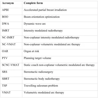
Table 1. A list of acronyms used throughout this review.
Table 2. A summary of the non-coplanar radiotherapy techniques discussed in this review.
Table 3. Summary of the applications, optimization methods, and readiness for clinical
implementation of the non-coplanar radiotherapy techniques discussed in this review.
Figure 1. The geometry for non-coplanar intensity modulated radiotherapy demonstrating (a)
the feasible non-collisional search space for non-coplanar beam orientation defined by gantry
and couch rotation angles (°), and (b) the final optimized beam orientations for a clinical
patient plan. STD = source to target distance; IEC = International Electrotechnical
Commission. Reprinted from Yu et al. [22], with permission from Elsevier.
Figure 2. Available treatment geometries for coplanar and non-coplanar radiotherapy. An
upper limit on treatment plan quality can be determined by distributing a large number of
beams over the full (a) non-coplanar or (b) coplanar space. Other techniques shown are: (c)
coplanar VMAT, (d) coplanar IMRT, (e) coplanar IMRT with optimized beam orientations,
(f) non-coplanar IMRT with optimized beam orientations, (g) static couch non-coplanar
VMAT, (h) non-coplanar trajectory VMAT tracing the great circles around the patient, and
(i), non-coplanar trajectory VMAT visiting nine optimized beam orientations. SnS = Step
and shoot, a type of IMRT delivery. BAO = beam angle optimized, equivalent to BOO in
this review. Reprinted from Wild et al. [39] with permission from John Wiley and Sons, ©
Figure 3. A coronal VMAT technique demonstrating (a) a discontinuous non-isocentric
trajectory, (b) the linac orientations corresponding to points on the trajectory, and (c) the
three-dimensional view of the beam and treatment geometry. Reprinted from Fahimian et al.
APBI Accelerated partial breast irradiation
BOO Beam orientation optimization
DWA Dynamic wave arc
IMRT Intensity modulated radiotherapy
NC-IMRT Non-coplanar intensity modulated radiotherapy
NC-VMAT Non-coplanar volumetric modulated arc therapy
OAR Organ at risk
PTV Planning target volume
SCNC-VMAT Static couch non-coplanar volumetric modulated arc therapy
SRS Stereotactic radiosurgery
SBRT Stereotactic body radiotherapy
TSP Travelling salesman problem
VMAT Volumetric modulated arc therapy
Non-coplanar intensity modulated
radiotherapy
C-arm linac Multiple static beams defined by linac gantry
rotation and patient couch rotation
[13-16, 18-22, 38]
Static couch non-coplanar volumetric
modulated arc therapy
C-arm linac One or more arcs, some with a non-zero
patient couch rotation
[40-44]
Coronal VMAT C-arm linac One or more arcs achieved with dynamic
patient couch rotation but with fixed or
limited linac gantry rotation. Trajectories
may be manually defined, calculated or
optimized.
[45-48]
Trajectory VMAT C-arm linac One or more arcs with dynamic patient couch
rotation and dynamic linac gantry rotation.
Trajectories may be manually defined,
calculated or optimized.
[39, 49-58, 60-61]
CyberArc Robotic arm
mounted linac
One or more arcs defined by robotic arm
orientation.
[70, 72]
Dynamic Wave Arc O-ring linac One or more arcs with dynamic linac gantry
rotation around the horizontal and vertical
lung [14]
brain [15, 21, 22]
head & neck [16] prostate [18, 19]
beams optimization
using existing methods [13-16, 18-22, 38]
implementation
SCNC-VMAT Brain [40-44] VMAT with multiple fixed
patient couch rotations Manual selection from limited arc set
Ready for
implementation Automated delivery and collision prevention on non-HyperArc platforms
Coronal VMAT Partial breast [45-48] Dynamic patient couch rotation
with fixed or limited linac gantry rotation
Manual [45, 46] or
algorithmic [47, 48]
trajectory definition Requires substantial further development Collision prevention Intrafraction motion Patient compliance
Investigation of other clinical sites Non-research delivery technology Trajectory VMAT Brain [49, 51-58, 61]
head & neck [39, 50, 60]
prostate [54, 56, 61]
lung [56-58, 61]
liver [58]
chest wall [61]
oesophagus [61]
Synchronized dynamic patient couch rotation and linac gantry rotation.
Manual [49, 50] or
mathematical [53]
trajectory definition Beam scoring [51, 52, 54, 55] or
fluence-based [39, 55-58, 61] trajectory
optimization Requires substantial further development Collision prevention Intrafraction motion Patient compliance
Non-research delivery technology
CyberArc Brain and prostate [70, 72] Arc delivery sequencing for
robotic arm mounted linac Dose mimicking and fluence-based trajectory optimization [70, 72]
Requires some further development
Integration into proprietary treatment planning and linac control software
Dynamic Wave Arc Brain [64]
metastatic disease [63, 65]
prostate [63, 65]
pancreas [63]
lung [63, 65]
breast [65]
Dynamic rotation of O-ring