Development of a Compact Divertor Plasma Simulator for
Plasma-Wall Interaction Studies on Neutron-Irradiated Materials
Noriyasu OHNO, Tatsuya KUWABARA, Makoto TAKAGI, Ryo NISHIMURA, Miyuki YAJIMA
1),
Akio SAGARA
1), Takeshi TOYAMA
2), Katuya SUZUKI
2), Hiroaki KURISHITA
2),
Tatsuo SHIKAMA
2), Yuji HATANO
3)and Naoaki YOSHIDA
4)Graduate School of Engineering, Nagoya University, Furo-cho, Chikusa-ku, Nagoya 464-8603, Japan
1)National Institute for Fusion Science, Oroshi-cho, Toki, Gifu 509-5292, Japan 2)Institute for Materials Research, Tohoku University, Oarai-machi, Ibaraki 311-1313, Japan
3)Hydrogen Isotope Research Center, University of Toyama, Toyama 930-8555, Japan
4)Research Institute for Applied Mechanics, Kyushu University, Kasuga-kouen, Kasuga, Fukuoka 816-8580, Japan
(Received 2 June 2017/Accepted 30 August 2017)
We have developed a compact divertor plasma simulator (CDPS) that can produce steady-state deuterium and/or helium plasmas with densities above∼1018m−3 for Plasma-Wall Interaction (PWI) studies of
neutron-irradiated materials. The maximum particle flux is about 1022m−2s−1. The CDPS was installed and is being
operated in the radiation-controlled area of the International Research Center for Nuclear Materials Science, Institute for Materials Research, Tohoku University. We are able to control sample temperature within uncertainty of 5◦C during plasma exposure by adjusting the cooling air flow rate to the sample holder. The CDPS has a sample-carrier system, which makes it possible to transfer a plasma-irradiated sample from the sample holder to an infrared heater for analysis using thermal desorption spectroscopy (TDS) without exposing it to the air. This avoids the oxidation of the sample and minimizes the time between the end of plasma exposure and TDS analysis. An ITER-like tungsten (W) sample (A.L.M.T. Corp.), which has been irradiated by neutrons to 0.06 dpa in a fission reactor, was exposed to a deuterium plasma in the CDPS. The experimental results clearly show that the total deuterium retention in the neutron-irradiated W sample increases significantly in comparison with a pristine W, as demonstrated by broadening of the TDS spectrum at high temperatures.
c
2017 The Japan Society of Plasma Science and Nuclear Fusion Research
Keywords: plasma-wall interaction, divertor plasma simulator, neutron-irradiated material, hydrogen isotope retention
DOI: 10.1585/pfr.12.1405040
1. Introduction
The understanding of the retention of hydrogen iso-tope in the plasma-facing wall and the process of releasing them from the wall are among the most important tasks associated with fuel (particle) control in nuclear-fusion power reactors. In particular, the accumulation of tritium (T) in the plasma-facing wall is an important issue for the safety of future fusion devices, such as ITER and DEMO.
At present, tungsten (W) is considered one of the most promising candidate materials for nuclear fusion reactors because of its high melting point, low sputtering yield and low tritium inventory. On the other hand, it is known that defects—such as atomic vacancies and voids in metals— act as trapping sites for hydrogen isotopes. Consequently, there are concerns that the amount of T retention in W may increase dramatically due to defects created by neutron ir-radiation.
As reviewed in [1], numerous deuterium (D) plasma irradiation experiments have been carried out using W samples in which defects have been introduced by heavy-author’s e-mail: [email protected]
ion beams simulating neutron irradiation. However, neu-tron irradiation causes uniform damage/trap creation in materials because of its uniform primary-knock-on-atom energy, while heavy-ion beams create defects peaked at a certain depth determined by the Bragg curve. For this reason, both the static and the dynamic characteristics of hydrogen-isotope retention in neutron-irradiated W may differ considerably from those produced by heavy-ion-beam irradiation.
Deuterium (D) retention characteristics—determined by exposing neutron-irradiated W samples to D plasmas— have been examined under the cooperative Japan-US pro-grams TITAN and PHENIX. The experiments were con-ducted at the Tritium Plasma Experiment (TPE) [2] of the linear plasma device at the Idaho National Laboratory fol-lowing neutron irradiation at the High Flux Isotope Reac-tor (HFIR) at Oak Ridge National LaboraReac-tory. The exper-imental results indicate that the D-retention characteristics of neutron-irradiated W are quite different from those of W damaged by heavy-ion beams [3, 4]. Therefore, it is nec-essary to continue systematic research on the
hydrogen-c
2017 The Japan Society of Plasma
duct PWI studies as well as for research on edge plasma physics in the divertor region. New DPSs (JULE-PSI [5], MPEX [6]) have been designed and are being constructed in large radiation-controlled area. However, because of cost and safety issues, it is difficult to build a new radiation-controlled facility with a DPS, so cost-effective alterna-tive approaches need to be considered. For this reason, we decided to develop a compact DPS (CDPS) with the same performance characteristics as a conventional large DPS but which can be operated in limited space and us-ing less electricity, in an existus-ing radiation-controlled area. Our goal is to use the CDPS to conduct PWI research on neutron-irradiated materials.
The CDPS we have developed at Nagoya University was installed in the radiation-controlled room of the In-ternational Research Center for Nuclear Material Science, Institute for Materials, Tohoku University (hereinafter re-ferred to as the “Oarai Center”) [7]. The Oarai Center has a long history of conducting neutron-irradiation tests using samples from nuclear reactors overseas (e.g., Bel-gian Reactor-2 [BR2]) as well as from reactors in Japan (the Japan Materials Testing Reactor [JMTR], the Exper-imental Fast Reactor [Joyo], and the Japan Research Re-actor [JRR-3]). Many neutron-irradiated W samples al-ready stored in the Oarai Center can be used for PWI research. Further, the Oarai Center has various analyti-cal instruments—such as a Transmission Electron Micro-scope, Scanning Electron MicroMicro-scope, Three-Dimensional Atom Probe and Positron Annihilation measurement ca-pability for neutron/plasma irradiated PFMs—which are available for use in the radiation-controlled area.
In this paper, we describe the CDPS we have devel-oped and report first results from D-plasma-irradiation ex-periments on neutron-irradiated W.
2. Configuration of the CDPS
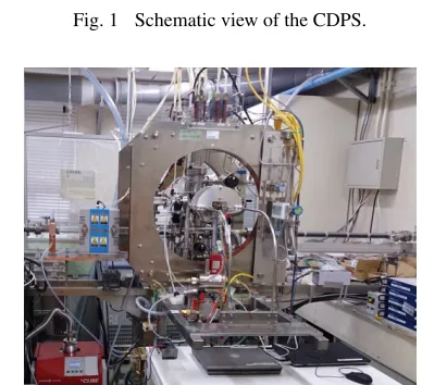
Figures 1 and 2 show a schematic view and a photo of the CDPS installed in the radiation-controlled room at the Oarai Center. The CDPS consists of two magnetic coils, a high-efficiency DC plasma source, a sample holder with air cooling and a sample-carrier system that is connected to an infrared heater for thermal desorption spectroscopy (TDS). The CDPS is about 1.7 m long, 0.8 m wide and 1.8 m high. It has smaller space requirements and lower electric-power consumption than conventional DPSs [8]. In the DC plasma source, high-density, steady-state plas-mas can be generated by the Phillips Ionization Gauge
dis-Fig. 1 Schematic view of the CDPS.
Fig. 2 Photograph of the CDPS installed in the radiation-controlled room at the Oarai Center.
charge. The key components of the CDPS are described in the following subsections.
2.1
DC plasma source and its performance
for plasma production
The DC plasma source consists of a LaB6cathode and
a water-cooled hollow copper anode as shown in Fig. 3. The plasma source is an improvement over that described in [9]. The two zigzag-shaped LaB6 electrodes shown in
the right-hand photo of Fig. 3 are connected in series and heated by a DC current. Each LaB6 bar is 1.5 mm thick
and 4 mm wide, and the bar is about 220 mm long. The LaB6 electrodes can be heated up to 1600 K with a
heat-ing power of about 600 W (DC current is about 85 A). In contrast, a conventional DPS requires several kW to heat the LaB6 cathode. The DC current heating of LaB6
trodes required by the CDPS contributes to its lower elec-tric power consumption. Including the copper anode, the plasma source is 26.7 cm long and 11.4 cm in diameter. The compactness of the plasma source also contributes to the reduced size of the device. The LaB6 electrodes are
Fig. 3 Schematic view of dc plasma source.
Fig. 4 (a) Schematic view of the sample holder. Photograph of generated helium plasma (b) and deuterium plasmas (c).
increases the effective cathode area, contributing to the high-density plasma production. The V-shaped LaB6
elec-trodes are supported by a boron nitride structure and are surrounded by a cylindrical tantalum (Ta) plate for thermal shielding.
Five CV/CC programmable regulated DC power sup-plies (KIKUSUI Electronics Corp.), each having a 19-inch rack width with a 1 U height, are utilized for plasma pro-duction. One DC power supply (PWX1500L: 0–150 A, 0–30 V) is used for cathode heating, and two DC power supplies (PWX1500L) are used for the two magnetic coils. To conduct the plasma discharge, two DC power supplies (PWX1500MH: 0–20 A, 0–230 V) connected in parallel are used under master-slave parallel operation. All power supplies are controlled by LabVIEW software on a per-sonal computer through a Ethernet connection.
Figure 4 (a) shows a schematic view of the sample
Fig. 5 Radial profiles of electron density in deuterium plasmas.
holder. The photographs represent helium (He) and D plas-mas generated by the DC plasma source described above. A fast reciprocating Langmuir probe is introduced into the plasma from the top of the vacuum vessel to measure the electron temperature and density as well as the plasma space potential. The W probe head with a diameter of 0.5 mm and a length of 2.0 mm, moves quickly up and down 9 mm away from the sample holder. Figure 5 shows plasma-density profiles measured in a D plasma as a pa-rameter of the discharge current. The D gas pressure is 1 Pa and the magnetic field strength is 14 mT. The full width at half maximum of the plasma density is about 15 mm. The plasma diameter coincides with the inner diameter of the hollow anode. Uniform plasma irradiation can be realized for the W samples (typical diameter of a neutron irradi-ated W sample is 6 mm (or 3 mm) in diameter). The elec-tron temperature distribution also peaks at the center; it is around 10 eV at the center and about 3 eV at the periph-ery. The plasma potential profiles, which depend weakly on the discharge current, are almost uniform in the radial direction; the potential is around−8 V at a discharge cur-rent of 48 A.
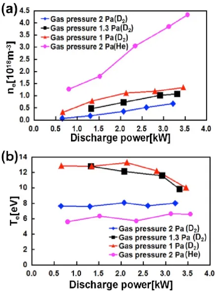
Figure 6 shows the discharge-power dependence of the electron density ne and the electron temperature Te
Fig. 6 (a) Electron density and (b) electron temperature as func-tions of the discharge power.
from Fig. 6 (a), the electron densityneis roughly
propor-tional to the discharge power. In the He plasma,nereaches
4.5×10¹⁸m−3 at a gas pressure of 2.0 Pa and a discharge
power of 3.5 kW, while the value ofnein the D plasma is
1.2×10¹⁸m−3 at a gas pressure of 1.0 Pa and a discharge power of 3.5 kW. We found that, in this gas pressure range, the lower the D gas pressure, the denser the plasma gener-ated. On the other hand,Teis almost constant, independent
of the discharge power, except for the lower range of D gas pressure at large discharge power.
We conclude that high-density, steady-state plasmas similar to those in current DPSs can be generated by the DC plasma source in the CDPS.
2.2
Sample holder and sample-carrier
sys-tem
Since the diffusion coefficients of hydrogen isotopes in materials are highly temperature-dependent, the sam-ple temperature during plasma exposure—together with the plasma-exposure time—determines the diffusion depth of hydrogen isotopes in materials. Especially in neutron-irradiated materials, the total hydrogen isotope retention depends strongly on the diffusion depth because neutron-irradiated materials have uniform distributions of de-fects with depth. In order to establish a high-accuracy, hydrogen-isotope-retention database for neutron-irradiated W based on experimental results, precise control of the sample temperature is therefore required during plasma
ex-mounted on the center of the molybdenum (Mo) stage, where it is held securely by three movable Mo hooks. The Mo stage and hooks can be replaced easily for diff erent-sized samples (3, 6, or 10 mm). The sample temperature is monitored with a tungsten-rhenium (5%Re-W26%), ce-ramic, sheath-type thermocouple. The head of the thermo-couple thermo-couple presses gently against the back of the sample to guarantee a good thermal connection between the ther-mocouple and the sample. During plasma exposure, the sample temperature is controlled by adjusting air-flow rate, which can be varied from 0 to 200 L/min with a mass flow controller (SEC-E80: HORIBA STEC Co., Ltd.). The air-flow rate is adjusted to keep the sample temperature con-stant, using a feedback control that monitors the sample temperature measured by the thermocouple. The sample holder can be biased externally, using a bipolar DC power supply to control the energies of the ions incident on the sample.
In general, the sample temperature increases gradu-ally toward the target value during plasma exposure, and the sample therefore has a history of plasma irradiation at temperatures different from the target value. In order to avoid this, we increased the sample temperature rapidly to the target value before plasma exposure, using electron bombardment caused by biasing the sample positively.
Fig. 7 Schematic view and photo of the air-cooled sample holder.
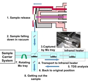
Fig. 8 Schematic diagram to explain how to transfer the sample form the sample holder to infrared heater for TDS analysis.
3. Deuterium-Plasma Exposure to
Neutron-Irradiated W
We have conducted D-plasma exposures of neutron-irradiated W samples utilizing the CDPS we have devel-oped. Two ITER-like W samples (A.L.M.T. Corp.), with diameters of 6 mm and thicknesses of 0.5 mm, were uti-lized in the experiment. One sample, annealed at 900◦C for 60 minutes, was irradiated by neutrons to 0.06 dpa in the fission reactor BR2 at the Belgian Nuclear Research Center at 290◦C. The surface of the neutron-irradiated W sample was electropolished before plasma exposure to re-move contamination of the sample surface produced dur-ing neutron irradiation. Another sample, without neutron irradiation, was annealed at 900◦C for 30 minutes. Each W sample was mounted separately on the sample holder and irradiated by a D plasma in the CDPS. Figure 9 shows the time evolution of the W-sample temperature, as well as the cooling gas flow rate. Before plasma exposure, a low-density plasma was generated and the sample holder was biased positively in order to heat the W sample to the target temperature of 290◦C by electron bombardment.
Fig. 9 Time evolution of air-flow rate (a) and sample tempera-ture (b) in the experiment.
Fig. 10 TDS spectra of D-retained W with and without neutron irradiation.
air-flow rate was also started as shown in Fig. 9 (a). The deuterium ion flux was 5.4×10²¹m−2s−1 and the incident
ion energy was about 100 eV, during the plasma exposure, which lasted 6000 s. Figure 9 (b) shows that the sample temperature during plasma exposure was kept constant at 290◦C within uncertainty of 5◦C by adjusting the cooling gas flow rate.
At 90 minutes after the end of the plasma exposure, the W sample was transported to the infrared heater, and the D retention was measured with TDS analysis with the rate of temperature ramp of 0.5 K/s. Figure 10 shows the TDS spectra of deuterium from neutron-irradiated W as well as pristine W. In comparison with the non neutron-irradiated W, the total D retention in the neutron-neutron-irradiated W is significantly increased, as indicated by the broaden-ing of the TDS spectrum toward high temperatures: this was also observed in a previous study [3, 4]. The total amounts of D retention in the neutron-irradiated W and in the pristine W are 3.2×10²¹D m−2and 7.6×10²⁰D m−2, re-spectively. This contrasts with the increase in total D reten-tion for the neutron-irradiated W (0.025 dpa at 50◦C) that is shown in Fig. 1 of [3], which is significantly greater than our experimental result (0.06 dpa at 290◦C). Further, the peak of the TDS spectrum is shifted to higher tem-peratures in [3] than in our experimental result. The dif-ference between these results is thought to be due to the
4. Conclusion
In this paper, we have described a CDPS that we have developed. It can be operated in a space-limited, radiation-controlled area and can generate high-density (above 1018m−3) D and He plasmas in a steady state, while
maintaining precise control of the sample temperature dur-ing plasma exposure. The CDPS is equipped with a TDS apparatus, so that gas retention in samples after plasma exposure can be analyzed without atmospheric exposure. We have also reported the first experiments from D-plasma exposures of neutron-irradiated W samples that we have performed in the CDPS. The experimental results show a significant increase in the D retention of the neutron-irradiated W. At present, the CDPS is being widely used in collaborative research and a comprehensive PWI study of neutron-irradiated materials is underway.
Acknowledgments
One of the authors (N. Ohno) greatly thanks Prof. T. Muroga in NIFS, Prof. O. Kaneko in NINS, and Prof. Y. Nagai in Tohoku University for their continuing encour-agement for this research. This work was performed under the auspices of the NIFS Collaboration Research Program (NIFS13KOBF026) and the Inter-University Cooperative Research Program of the Institute for Materials Research, Tohoku University (Proposal no.17M0018, 16M0017).