OPTIMISATION OF THE BEARING SURFACE DESIGN
OF TOTAL KNEE REPLACEMENTS
by
Shivani Sathasivam
SUBMITTED FOR THE DEGREE OF DOCTOR OF PHILOSOPHY
IN THE UNIVERSITY OF LONDON
ProQuest Number: U643549
All rights reserved
INFO RM A TIO N TO ALL U SER S
The quality of this reproduction is dependent upon the quality of the copy submitted.
In the unlikely event that the author did not send a complete manuscript
and there are missing pages, these will be noted. Also, if material had to be removed, a note will indicate the deletion.
uest.
ProQuest U 643549
Published by ProQuest LLC(2016). Copyright of the Dissertation is held by the Author.
All rights reserved.
This work is protected against unauthorized copying under Title 17, United States Code. Microform Edition © ProQuest LLC.
ProQuest LLC
789 East Eisenhower Parkway P.O. Box 1346
ABSTRACT
A total knee replacement consists of a double-convex, cobalt-chrome layer
which resurfaces the femur, and a cobalt-chrome tibial tray with a double
concave polyethylene insert. The longevity of knee replacements is limited, as
the polyethylene suffers from fatigue resulting in delamination wear. Previous
researchers have analysed the stresses produced in tibial inserts of different
designs. However, these studies do not consider the relative displacements and
rotations which occur between the prosthetic components during gait. Various
designs of knee replacement are currently available and the aim of this study
was to investigate the effect of bearing surface geometry on durability.
Rigid body analyses were used to predict the kinematics of different
designs of knee replacements during one level walking cycle. The effects of soft
tissue restraints were included to compare designs of different conformities, and
friction had to be included to obtain realistic motion. These theoretical results
were validated by a knee simulating machine. Finite element analyses were
carried out at intervals during the walking cycle, to calculate the stresses
associated with the orientations of the prosthetic components predicted by the
rigid body analyses. Damage functions were formulated which accumulated the
fluctuations and average magnitudes of the stresses produced in each element
of the tibial inserts. The maximum shear stress damage function to predict
subsurface cracking in the polyethylene was equivalent to the strain energy
density criterion, used by material scientists to predict crack growth. Using the
damage function values, damage maps were generated to indicate the regions
of the polyethylene which were most prone to fatigue.
Varying the geometry of the prosthetic bearing surfaces to cover the
range of knee replacement designs currently available produced significant
differences in the values of the damage functions, suggesting differences in their
durabilities. Furthermore the damage functions were used to optimise the
prosthetic bearing surface geometries so that the least destructive fatigue
mechanisms in the polyethylene would be induced while conserving the laxity of
TABLE OF CONTENTS
page
1. INTRODUCTION |11
1.1 MODERN TOTAL KNEE REPLACEMENT DESIGNS | 12
1.2 KNEE KINEMATICS 16
1.3 WEAR AND STRESSES IN THE POLYETHYLENE 19
1.4 KNEE MODELS AND THEIR APPLICATION 21
2. A SIMPLIFIED MODEL OF THE TOTAL KNEE REPLACEMENT BEARING
SURFACES 28
2.1 PARAMETRISATION OF THE BEARING SURFACE GEOMETRY 30
2.2 DETERMINATION OF CONTACT STRESSES ON THE TIBIAL COMPONENT 31
2.3 INTERCHANGEABILITY BETWEEN SIZES OF THE COMPONENTS 34
2.4 CONSIDERATIONS FOR THE SAGITTAL PLANE 35
2.5 DISCUSSION 37
3. GENERATION OF PROSTHETIC MODELS 49
3.1 THE FEMORAL COMPONENT 51
3.2 THE TIBIAL INSERT 55
3.3 APPLICATION OF MODELLING PROGRAMS (1) - MANUFACTURE OF CUSTOMISED
KNEE REPLACEMENTS 57
3.4 APPLICATION OF MODELLING PROGRAMS (2) - FINITE ELEMENT ANALYSIS OF
MOBILE BEARING TIBIAL INSERTS 59
4. USING RIGID BODY ANALYSIS TO DETERMINE PROSTHETIC KNEE
KINEMATICS 75
4.1 INTRODUCTION 76
4.2 METHODS & MATERIALS 78
4.3 RESULTS 91
4.4 DISCUSSION 94
5. VALIDATION OF THE RESULTS PRODUCED BY THE RIGID BODY
5.1 INTRODUCTION 111
5.2 METHODS AND MATERIALS 113
5.3 RESULTS 117
5.4 DISCUSSION 120
6. DETERMINING THE VARIATION OF STRESSES IN THE TIBIAL INSERT
DURING GAIT 136
6.1 INTRODUCTION 137
6.2 METHODS AND MATERIALS 138
6.3 RESULTS 142
6.4 DISCUSSION 144
7. DAMAGE FUNCTIONS TO PREDICT DELAMINATION WEAR 162
7.1 INTRODUCTION 163
7.2 METHODS & MATERIALS 164
7.3 RESULTS 169
7.4 DISCUSSION 171
8. SUMMARY & CONCLUSIONS 182
9. REFERENCES 194
LIST OF FIGURES page
CHAPTER 1
1 ) An example of a condylar total knee replacement. 25
2) An example of a mobile bearing total knee replacement. 25
3) An example of a superstabilised total knee replacement. 26
4) Examples of hinged total knee replacements. 26
5) Subsurface cracking seen by Dr. G.W. Blunn in a thin section 27
from a retrieved tibial insert.
6) A retrieved delaminated tibial insert. 27
CHAPTER 2
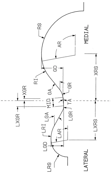
1 ) Terminology used to describe the simplified models of the 42
total knee replacement bearing surfaces.
2) Function Ce (containing modulus of elasticity of plastic) plotted 43
against function Kd (containing relative radii of curvature of the
bearing surfaces).
3) The effect of varying the frontal and sagittal tibial radii on the maximum 44
contact stresses (1000N compression).
4) Using PEA to examine interchangeability between sizes. This example 45
shows a case where the outer tibial radius is 45mm and the femoral
component is 6% larger than standard. For clarity, all the elements
are not shown.
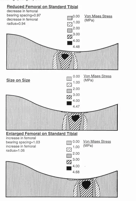
5) Contact stresses for the frontal plane and contact point locations for46
interchanged components where the outer tibial radius is 40mm.
The radii have been scaled by 6% and the bearing spacings by 3%.
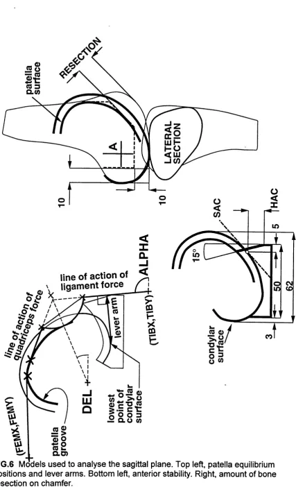
6) Models used to analyse the sagittal plane. Top left, patella equilibrium 47
positions and lever arms. Bottom left, anterior stability. Right, amount
of bone resection on chamfer.
7) Lever arms of the patella ligament over a range of flexion angles, for 48
CHAPTER 3
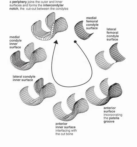
I ) Different regions which make up the femoral component. 64
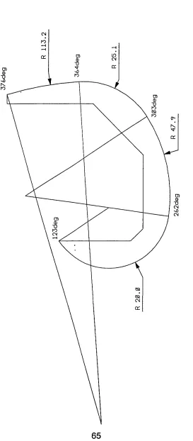
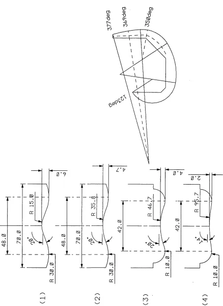
2) Typical arcs defining the sagittal profile of the femoral component. 65
3) A typical set of reference frontal sections. 66
4) Variable parameters for a reference frontal section. 67
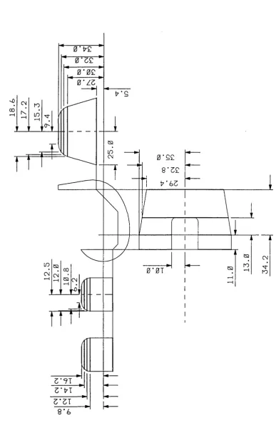
5) Defining the periphery of the femoral component. 68
6) Defining the regions of the femoral component which interface with the 69
bone.
7) a)The rigid body model of the tibial component, b) The finite element 70
model of the tibial component.
8) A superstabilised stainless-steel femoral component and casting 71
waxes manufactured using a CNC macine and computer software
developed to generate surface models of the prosthetic components.
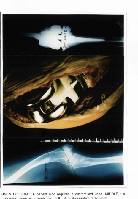
9) BOTTOM : A patient who requires a customised knee. MIDDLE : 72
A customised knee being implanted. TOP : A post-operative radiograph.
10) Graphs comparing the maximum shear and maximum principal 73
stresses in the tibial inserts of five mobile bearing designs with
different conformities.
I I ) Maximum shear stress contoured plots for the very conforming 74
and unconforming mobile bearing designs.
CHAPTER 4
1 ) The component surfaces are described by points on a grid. The surface 97
in the vicinity of a grid point is described by a polynomial. The normal
vector is then calculated.
2) A schematic of the computer model. 98
3) Including relative surface velocities in the computer model. 99
4) Determining the friction direction. 100
6) Force-displacement and torque-rotation curves, computed by the model. 102
Positive displacement indicated anterior movement of the tibial
insert. Full strength bumpers were used anteriorly and posteriorly.
7) The effect of friction coefficient on the A-P displacement (left) and 103
internal-external rotation (right) predicted by the computer model.
Full strength bumpers posteriorly, one third stength anteriorly.
8) Curves comparing the effect of combining flexion with anterior- 104
posterior force. The same anterior-posterior force cycle was applied
to all three tests, and the direction of the flexion cycle was changed.
9) The effect of soft tissue restraint for a design with sagittal tibial 105
radius 50mm anteriorly, 80m posteriorly and one with sagittal tibial
radus 120mm.
10) A combination of anterior-posterior force and internal-external torque 106
cycles were input to the computer model of the CONDYLAR design.
The compression load was 1500N and the knee was at 60deg flexion.
11 ) Displacements and rotations of the tibial insert relative to the femoral 107
component in level walking. Input cycles provided by J.P.Paul.
12) To include the effects of tractive rolling, different tolerances of relative 108
displacement between the prosthetic components were set, within
which pure rolling was allowed to occur.
13) Predicted contact point locations for different outer frontal plane tibial 109
radii, during the stance phase of a normal gait cycle. The sagittal radii
were: femoral distal 48 mm, femoral posterior 20 mm, tibial 56 mm.
CHAPTER 5
1) TOP : A schematic of the knee simulating machine. BOTTOM : The knee 124
simulating machine.
2) a) One third strength used at the anterior of the tibial insert, b) Full 125
strength bumpers used at the posterior of the tibial insert.
3) Force-displacement and torque-rotation curves, comparing theoretical 126
and experimental results. Positive displacement indicates anterior
movement of the tibia. Full strength bumpers were used anteriorly
4) A-P force cycles were applied to the NEXGEN and RFC knees at different 127
flexion angles, with and without a bumper system to represent soft tissue
restraints with the ACL resected. The compression load was 1500N.
5) Int-ext torque cycles were applied to the NEXGEN and RFC knees at 128
different flexion angles, with and without a bumper system to represent
soft tissue restraints with the ACL resected. The compression load was
1500N.
6) Curves produced by the knee simulating machine for tests where 129
anterior-posterior force and flexion were combined in different ways.
7) Results from the knee simulating machine for tests where anterior- 130
posterior force and torque were combined. RBA4 is the internal-external
rotation, ZBA4 is the anterior-posterior displacement of the tibial insert.
8) Comparing the predictions of the computer model for output rotations 131
and displacements during level walking with results from the knee
simulating machine. Input cycles provided by J.R.Raul.
9) Total anterior-posterior displacement plotted against flexion for six 132
knee specimens.
10) Anterior-posterior displacement plotted against anterior-posterior force 133
at 3 compressive forces for a typical knee specimen.
11 ) Rotation plotted against torque at 3 compressive forces for a typical 134
knee specimen.
12) Graphic showing the incompatibility of a TKR with normal knee motion 135
and RCL tension, due to the preferred TKR position at the bottom of the
tibial dish under the compressive forces acting during activities.
CHAPTER 6
1 ) Finite element meshes of the femoral and tibial components of a knee 150
replacement.
2) Defining the geometry of DESIGN 1. 151
3) The input cycles of flexion, anterior-posterior force, internal-external 152
torque and compression load obtained from T.R. Andriacchi.
4) Values for the maximum contact pressure on the tibial insert during the 153
5) The varying shapes and locations of the contact areas for DESIGNS 154-160
1 and 2 during gait.
6) The fluctuating maximum shear and maximum principal stresses for the 161
elements of DESIGNS 1 and 2 which scored the highest average stresses.
CHAPTER 7
1 ) Variability in total knee replacement design : femoral outer frontal radius, 176
femoral posterior-distal transition angle, clearance of the tibial insert from
the femoral component and tibial sagittal radius.l
2) The total anterior-posterior and rotational laxities of the 16 knees 177
during the stance phase of gait.
3) The damage scores accumulating a) the fluctuating maximum principal 178
stresses b) the fluctuating maximum shear stresses for 16 knees
during the stance phase of gait.
4) Maximum shear damage function maps for 3 designs ( f i t l , f1t4, f4t4). 179
5) The anterior-posterior and rotational motions during the gait cycle of the 180
knee with the least damage score (f4t4) and the optimal knee (f4t3)
with increased laxity. Positive values mean that the femoral component
moves fon/vards and internally relative to the tibial insert.
6) The NEXGEN cruciate retaining design. 181
CHAPTER 8
1 ) Using contact pressures versus damage scores to compare 191
susceptibilities to delamination wear of tibial inserts in different
knee designs.
2) Retrieved tibial components collected by Dr. Gordon Blunn at the 192
Centre for Biomedical Engineering , Stanmore.
4) LIST OF TABLES
page
CHAPTER 3
Five mobile bearing designs. 60
CHAPTER 5
Variation of the coefficient of friction with conformity and compression 177
load.^
CHAPTER 6
Defining the geometry of two commercially available designs. 139
CHAPTER 7
Values for the four variable parameters of the 16 knee designs. 165
ACKNOWLEDGEMENTS
I thank my supervisor, Prof. P.S. Walker for his guidance and support, and for
giving me the opportunity to work at the Centre for Biomedical Engineering in
Stanmore.
I am also grateful to Dr. Luger for his help with the cadaveric experiments,
Karoline Krohn and Britta Ziimmerman for helping to carry out some of the
experiments on the knee simulating machine, Professors Paul and Andriacchi for
providing the input cycles for level walking, and Dr.Mike Dewar, Ms.Jessie Smart
and Ms. Edith Castle for their interest and encouragement.
This work was funded by the Medical Devices Agency of the Dept, of Health
(U.K.) in conjunction with a consortium of manufacturing companies (Biomet,
Howmedica, Sulzer, Waldemar-Link and Zimmer), the North-West Thames
Regional Health Authority Locally Organised Research Program and the Bristol
Chapter 1
1. INTRODUCTION
1.1 MODERN TOTAL KNEE REPLACEMENT DESIGNS
Total knee replacements are used for the treatment of degenerating joint
surfaces, usually caused by arthritis, and for gross knee instability, which may be
due to irregular bone geometry or loose ligaments. It is not necessary to
reproduce the bearing surfaces of the femur and tibia anatomically when
designing the prosthetic components. However, the variety of total knee
replacements currently on the market suggests that there is still not a consensus
amongst designers on the effects of geometry on the function and longevity of
these implants. Even though they are used to treat medical conditions, total
knees must be designed and tested in the same manner as engineering
components, ensuring that they can withstand the forces exerted on them and
that their kinematics replicate the natural joints which they replace.
Total knee replacements are assemblies of four basic components, a
cobalt chrome tibial tray, an ultra-high molecular weight polyethylene tibial insert,
a cobalt chrome femoral component and a polyethylene patella button. The
components are assembled by the surgeon in the operating theatre. A slice of
bone is removed from the top of the tibia and a hole is drilled into the trabecular
bone. The tibial tray is fitted into the tibia usually with cement, by inserting its
central stem into the hole for anchorage, the plateau of the tray replacing the
resected bone. The tibial insert is fixed into the tray to act as a bearing surface
between the tibial tray and femoral component. Bone cuts are made to the femur
so that the femoral component can be fitted, resurfacing not only the part of the
bone which interfaces with the tibial insert but also that which comes into contact
with the patella. For this purpose a patella groove runs up the anterior face of the
femoral component veering laterally, allowing the button which resurfaces the
patella to slide up and down in a natural manner. There are different variations of
total knee replacement available, depending on the amount of stability required.
However, it generally follows that the more stability provided, the more
‘Condylar’ knee replacements (Fig.1) in many forms have been designed
since the middle of the ninteenth century. Gunston [1969] is usually credited with
the first cemented metal-on-plastic knee replacement. Working in Charnele/s
department in the 1960s he produced a desigrl consisting of narrow femoral
runners embedded in the femoral condyles articulating on two separate plastic
tracks embedded in the upper tibia. This design was used in large numbers by
the Mayo Clinic group during the 1970s. The results were generally good but
there was an increasing incidence of subsidence of the components as well as
wear and deformation [Lewallen et al, 1984]. The Mayo group and others went on
to develop the Geomedic knee which was very conforming with large contact
areas but it was too constrained [Skolnick et al, 1976]. Freeman and Swanson
were the first originators of a total knee design which replaced the entire femoral
and tibial condylar surfaces [Freeman et al, 1974]. This design was first implanted
in 1970. They introduced the roller-in-trough concept and instrumentation which
produced rectangular bone cuts. In addition, the femoral and tibial surfaces could
rotate and slide at limiting values, so that the forces and moments were not
entirely transmitted to the interface between the bone and the prosthesis. The
Freeman-Swanson prosthesis was later developed into the Freeman-Samuelson
prosthesis which included a metal base-plate for the tibial component.
The first truly anatomical approach was by Seedhom [Seedhom et al,
1974] who replicated the femoral condylar surfaces and produced tibial surfaces
which were imprints of the actual femoral-tibial motions. He determined that three
sizes of prosthetic knee would suit the needs of 90% of patients [Seedom et al,
1972]. Similarly, Town ley [1985] took an anatomical approach, including a patella
flange. However, his experience led him to design five sizes because he believed
that the wrong size of prosthesis could compromise the stability and range of
motion of the joint. In recent years, interchangeability of components, where
different sizes of femoral and tibial components can be mated, has also become
a feature of knee designs.
The Total Condylar Prosthesis designed by Ranawat, Insall and Walker
was first implanted in 1973. It was designed to improve upon the performance of
stability [Insall et al, 1979]. In addition, the Total Condylar had an anterior flange
for the patella on the femoral component and a central peg on the tibial
component to provide fixation which had been lacking in previous knee designs.
This design proved to be very successful and Is still implanted, though it is
reported that the most commonly used condylar knee replacement used today is
the Insall-Burstein II posterior stabilised design which requires the cruciates to be
removed. Instead, femoral roll-back is guided by a wedge of polyethylene on the
tibial insert which engages with a bar across the femoral condyles.
Condylar knee replacements are the most conservative when considering
bone removal and also allow the most freedom of movement. Tibial trays and
femoral components of many of this type of knee have slots which allow the
posterior cruciate ligament to pass through so that it can continue to function after
surgery. The geometries of the interfacing surfaces of the femoral component and
the polyethylene tibial insert dictate both the magnitude of the stresses generated
in the latter and the sliding patterns on its surface during activity cycles. In the
natural knee, stability is provided by the ligaments and the joint capsule. On the
other hand, the laxity and stability of a condylar knee replacement is balanced by
the dishing of the tibial insert and the ligaments and soft tissues that remain, the
tibial insert dominating if it is very dished. It is the design of these bearing
surfaces which is the focus of this thesis.
It became apparent that the tibial inserts of some condylar knees were
suffering from delamination wear [Wright & Bartel, 1986] where severe cracking
occurs in the polyethylene leading to rapid disintegration of the bearing surface.
In order to reduce the stresses in the polyethylene, the tibial inserts could be
designed to be very conforming to the femoral component, however this would
not allow relative motion between the femur and tibia, which is necessary for
natural gait patterns to be reproduced. This problem had been solved by
releasing the tibial insert from the tray to create a mobile bearing which could
slide around with only soft tissues and stops built into the tibial tray to restrain its
motion (Fig.2).
bearing knee was the Oxford knee, designed in the early 1970s. It had completely
conforming bearing surfaces without clearances [Goodfellow et al, 1987], and its
unicompartmental design allowed both cruciate ligaments to be retained.
Goodfellow and O’Connor [1978] followed the principle of the four bar linkage
mechanism to replicate normal motion with the presence of both cruciates.
Evidently, the conforming surfaces produced relatively low contact stresses which
has resulted in very low wear rates even after twenty years of implantation.
However, due to its complete lack of constraint, there are limitations to the use o f-
this design [O’Connor & Goodfellow, 1996] when the cruciates are absent,
especially the anterior cruciate ligament. Buechel and Pappas designed more
constrained mobile bearings. In one design, the motion of the plastic inserts is
guided in tracks on the metal tibial tray and in another design the plastic insert
rotates in the tibial tray. This design, the LCS rotating platform, is the most
commonly used mobile bearing design today.
The two types of knees described would not be suitable for cases where
the ligaments are in poor condition. ‘Superstabilised’ knees (Fig.3) are similar to
condylar knees except that a rounded post protrudes from the tibial insert and is
housed in a cavity in the femoral component. When the knee flexes, the post and
the housing work as a cam mechanism. This feature controls the amount that the
femoral component rolls back with flexion and its varus-valgus tilting. The Total
Condylar II [Walker, 1985] was one of the first knees designed along these lines.
Superstabilised knees require more bone removal to accomodate the cam but not
as much as that required by ‘hinged’ knee designs (Fig.4) where a large chunk of
bone must be removed to make room for the hinge.
Hinged knees provide the ultimate restraint because the femoral and tibial
components are linked together preventing relative motion between the two parts
except for flexion/extension. The Attenborough [Attenborough, 1976] was one of
the first hinged designs. The femoral component had a stem articulating in a ball
socket attached at its centre. Unlike other hinged knees of its time, such as the
Walldius and Shiers hinged prostheses, it could internally and externally rotate.
disturbance from the previous implant have left the knee in disarray and in need
of reconstruction.
Total knee replacements are not permanent or fault-free solutions to bone
degrading conditions. Each type of knee replacement described has drawbacks.
Condylar knees generally fail due to delamination when high stresses are
repeatedly exerted on the tibial insert. Mobile bearing knees suffer from abrasion
and burnishing due to large contact areas at two interfaces. Superstabilisers can
fail by delamination or excess force being applied to the stabilising post. Hinges
fail by loosening when the constraint provided by the hinge causes load to be
transmitted to the bone. However, the variability between patients, the sparcity of
information about knee forces, the problems of recreating the environment in the
joint capsule, the changing material properties of sterilised polyethylene with time
and the requirement to use only biocompatible materials make improving the
durability of knee replacements a difficult task.
1.2 KNEE KINEMATICS
In order to design total knee replacements, the input forces to the natural knee
joint and the output motions must be known. The knee is subjected to
compression force, anterior-posterior shear, medial-lateral shear, internal-
external torque, flexion and varus-valgus moments. The magnitudes of these
forces vary considerably with different activities, the functional loads being either
the ground reaction force applied to the foot or the inertial load of the leg, the
former reaching a maximum of 1.3 times body weight during walking to more than
twice body weight during running [Burstein, 1984] and even higher for activities
such as squatting. As long as the tibial insert can withstand the stresses imposed
without failing, and the combination of the prosthetic components functions
naturally, it does not matter how far their designs deviate from the natural bone
surface geometries. If however the artificial bearing surfaces do not allow natural
motions to occur, the joint becomes overconstrained, forces are transmitted to the
junctions between the prostheses and the bones, and loosening occurs.
Therefore, the laxity of the natural knee is the initial criterion when deciding on
In order to measure the three rotations, and three translations of the
natural knee, or to apply them when designing prosthetic components, a
coordinate system must be defined relative to which movement occurs. In the
literature, flexion is said to occur about an instant centre of rotation in the femur.
However, a fixed coordinate system is preferable so that quantities such as total
laxity of the joint can be determined. Wismans et al [1980] used Euler’s angles to
apply flexion, varus/valgus tilt and internal/external rotation to the femur relative
to a fixed tibia. Translations were applied subseqently. Grood & Suntay [1983]
made a further development by defining a joint coordinate system which was
independent of the order in which rotations and translations were imposed.
Cadaveric studies have been carried out to determine the effect of joint
load on knee laxity and stability [Markolf et al, 1981]. They showed that the
combination of compressive load applied to the joint surfaces, the geometry of
the knee joint, tissue compliance and friction between the cartilage surfaces had
a stabilizing effect on the natural knee, protecting its ligaments. Joint load is
generated by body weight and muscle forces activated by the neuromuscular
control sytem. This causes problems when using laxity as a criterion for knee joint
design. The forces exerted by the muscles may alter when the brain senses that
the artificial knee has a different geometry and friction coefficient compared to the
natural knee, changing the stiffness and laxity of the prosthetic knee. In this
thesis, it was assumed that the muscle forces for the prosthetic knee were the
same as for the natural knee.
Morrison [1968] used a force plate to measure the ground reaction force of
subjects with natural knees as they performed activities while being filmed.
Markers were used to determine the acclerations of the lower limb segments and
a multi-channel electro-myograph recorded the muscle activity. By summing the
ground reaction force, gravitational and acceleration effects, the external force
system acting on the knee joint was obtained. Surprisingly, hardly any data on
gait forces has been published since Morrison, though more recently telemetric
methods have been used to measure knee forces directly [Taylor et al, 1997].
La Fortune et al [1992] determined the knee motions of five patients during
three-dimensional relative motions. Knee motions are usually referred to as active
or passive, depending on whether the muscles are acting, the muscles having a
significant effed. In the literature, references are often made to motions of the
tibiofemoral joint. Convention has defined this as relative motion of the tibia with
respect to the femur. However, in this thesis, the contact points on the tibial insert
were compared for different knee designs [Sathasivam & Walker, 1994], so the
relative motion of the femur on the tibia was considered. The natural knee flexes
during stance and swing to approximately 20deg and 60deg respectively.
Lafortune et al showed that flexion during walking was accompanied by
approximately 15mm posterior draw and Sdeg internal rotation of the tibia, where
the tibia was defined to rotate about its long axis and the origin of the femoral
reference frame was located at the deepest point of the intercondylar fossa.
The question is whether force data similar to that calculated by Morrison or
La Fortune's displacement data should be input to a prosthetic knee model, in
order to determine realistic estimates of the magnitudes of the stresses and
positions of the contact areas in the tibial insert. The choice between force and
displacement control is a controversial one. In favour of force-control, it could be
argued that different knee designs have different laxities due to their variations in
conformity. On the other hand, muscle contracture may dominate resulting in
unconforming designs moving in a similar way to moderately conforming designs,
suggesting that displacement-control would be more appropriate.
Clinical observations support both sides. Andriacchi et al [1982] showed
that patients with certain knee replacements showed signs of gait adaptation, that
is, their motion patterns were different from normal. A force-controlled model
would show gait adaptations for different designs. In this thesis, output motions
for the input forces of level walking provided by Andriacchi et al [1995] were
determined. The restraining effects of the soft tissues were taken into account in
order to compare fairly knees with different conformities between the femoral and
tibial components. However, bearing in mind that the anterior cruciate ligament is
resected for most condylar replacements, Vergis & Gillquist [1997] showed that
subjects with ruptured anterior cruciate ligaments had similar motion patterns to
would assume that muscle contracture makes the stabilising mechanisms of the
knee redundant during active motion.
1.3 WEAR AND STRESSES IN THE POLYETHYLENE
The tibial inserts of total knee replacements suffer from at least three modes of
wear, adhesion, abrasion, and fatigue [Fisher & Dowson, 1991]. Adhesion is
where asperities on both bearing surfaces cold weld together then break during
sliding, resulting in transfer of polyethylene to the femoral component. The
transferred polyethylene in turn rubs against the tibial insert producing more wear
by abrasion. Abrasion usually occurs when asperities on a hard material plough
through a softer material or when loose particles introduced between the bearing
surfaces grind as they roll between them. However, the most catastrophic of
these mechanisms is fatigue, where subsurface cracks (Fig. 5) propagate and
unite, leading to the release of large pieces of polyethylene and eventually the
delamination of the tibial insert (Fig.6).
Retrieval studies have shown that in general the more conforming designs
suffer less from fatigue failure [Collier et al, 1991]. However, they do suffer from
abrasion [Landy & Walker, 1988], especially if the polyethylene surface is very
dished and entraps foreign bodies. The patterns of wear are varied, affected by
variables other than the geometry of the bearing surfaces. However, Lewis et al
[1994] retrieved tibial components of unconforming designs which exhibited
severe delamination in the posterior-medial region. Blunn et al [1992] observed
that a low conformity design (Marmor) did not delaminate while a design of similar
conformity (St. Georg) did. This was probably due to the different manufacturing
methods used for the tibial inserts, that of the Marmor being compression
moulded rather than machined.
Mobile bearing knees are generally reported to be successful, despite the
fact that abrasion of large contact areas between two pairs of interfaces may
produce a large quantity of small polyethylene particles. However, the majority of
knees implanted today are condylar designs, mainly because they are the
determine the design features which make condylar knees more resistant to
delamination wear.
Material scientists have tried to predict fatigue failure by using stress-
based, strain-based and energy-based criteria. Ellyin [1989] has shown that
cracks initiate and propagate when the strain energy density is high. Tests were
carried out on specimens which were cyclically loaded in a uniaxial direction.
There was a correlation between the total strain energy density and number of
cycles to failure. This has le d lo the formulation of life prediction models using
cyclic strain energy density as a criterion for multiaxial fatigue failure. A stress-
based approach was applied to formulate damage functions to predict the
susceptibility to delamination wear of tibial inserts in this thesis. Bartel [1986]
emphasised the importance of the maximum shear stress and maximum principal
stress when determining if tibial inserts could withstand static loads. In this thesis
a further step was taken to analyse these stresses during fatigue loading. This
was achieved by using the damage functions to accumulate the fluctuations and
magnitudes of the maximum shear and maximum principal stresses during gait
for the entire volume of polyethylene in tibial inserts of different knee designs.
Both stresses were required to account for the difference in the compressive and
tensile strengths of polyethylene.
Consider a total knee replacement to be simplified to a model of a cobalt
chrome sphere loaded onto a flat polyethylene slab. A polyethylene element on
the surface in the centre of the contact area, experiences vertical compressive
forces due to the loading sphere and horizontal compressive forces from the
surrounding bulk of plastic. This element does not suffer from a significant
amount of strain. Below the surface, both the horizontal and vertical compressive
forces decrease with depth, the former decreasing more rapidly than the latter.
Therefore, the strain of the polyethylene is greatest in the subsurface region at a
depth where the horizontal compressive forces have almost diminished and the
vertical compressive forces are still high, and the difference between them
reaches a maximum. For elements in other regions of the polyethylene, which
have more complex stress states, the strain is greatest when the difference
where the most subsurface strain occurs, was used as a parameter on which to
base a damage function to predict subsurface cracking.
However, it is visible from retrievals, that cracks also emanate from the
surface of the polyethylene. These cracks would not be predicted by a damage
function based on maximum shear stress. At the surface, around the contact
region, the polyethylene is subjected to low minimum principal stresses and
relatively high maximum principal stresses. The difference between these two
quantities does not peak as high as the difference between the subsurface
principal stresses, but the tensile nature of the maximum principal stress in the
region around the contact area leaves the polyethylene vulnerable to failure. This
is because polyethylene is weaker in tension than in compression. Therefore
maximum principal stress was used as a parameter on which to base a second
damage function to predict surface cracking.
1.4 KNEE MODELS AND THEIR APPLICATION
It appears that there are two conflicting criteria for designing the bearing surfaces
of knees. They should accommodate natural kinematics as well as resist abrasive
and delamination wear. Retrieval studies have highlighted the pitfalls of the early
designs. However, variables such as thickness of the tibial insert, polyethylene
quality, manufacturing methods, sterilisation procedures, surgical accuracy and
patient activity levels make it impossible to compare solely the effects of different
bearing surface geometries. Meanwhile, new designs are produced every year
and it will only be clear if improvements have been made to the bearing surface
geometry two decades after they have been implanted. Computer models are
useful tools for simplifying complex systems, and also for optimising designs
which are defined by variable parameters. Therefore they are ideal for tackling
the problem of identifying the knee designs which are likely to suffer from
delamination wear and even suggesting new ones.
The earliest models of the knee considered the sagittal plane only, such as
the four bar linkage which studied the action of the cruciate ligaments [Zavatsky &
O’Connor, 1992]. Two-dimensional models are still used today to examine flexion
frictional forces than sliding, and may he the cause of a recently observed striated
wear pattern. Wismans [1980], however, developed one of the first three-
dimensional knee models which included bone geometry and ligament and
capsule restraints. He iteratively solved equilibrium equations to determine the
relative positions of the femur and tibia for input forces, and spring elements were
used to represent ligament restraints. This was a quasi-static direct dynamics
model because it considered the motion of the knee to be a seqence of static
positions which varied gradually with time. Andriacchi [1983] and Blankevoort
[1991] also created quasi-static knee models. These models increased the
understanding of the way the knee worked, in particular, the interaction between
the joint surfaces and the ligaments. However, it is not clear what practical
applications models such as these have.
The first prosthetic knee models were used to solve the problem of fixation
of tibial components to the bone. However, Bartel et al [1986] carried out one of
the first studies to analyse the stresses within polyethylene tibial inserts to
understand why these components failed. They used a combination of the
elasticity solution and finite element analysis with bilinear material properties to
show that the thickness of the polyethylene below the dishing should be at least
8mm in order to maintain low stresses, even though surgeons at the time
preferred thinner tibial inserts which conserved more bone. More recently, Jin et
al [1995] also used the elasticity solution to carry out a parametric analysis to
determine the stresses for combinations of femoral and tibial surfaces with
different geometries. The results from these studies are useful, but do not help to
predict fatigue failure of polyethylene tibial inserts, for which information on the
fluctuating nature of the stresses during gait is required.
As finite element analysis became more accessible and cheaper to run,
the more sophisticated the models generated. Mottershead et al [1996] carried
out finite element analyses of tibial inserts using 20-node bricks and found that
the Hertz equations which were originally used to calculate stresses in the knee,
and finite element analyses using 8-node bricks, underestimated the stresses.
This study used Gaussian point constraints to apply loads. However, the
element packages has meant that analysing the femoral-tibial contact conditions
is a relatively simple task.
The current interest in the effects of irradiation on oxidation [Bostrom et al,
1994], and the subsequent increase in the elastic modulus of the polyethylene at
the surface has produced more problems to be solved by computer models. Hahn
et al [1995] built models of prosthetic knees to determine the effects of varying
the elastic modulus of polyethylene to simulate the changes produced by
irradation and oxidation. Kurtz et al [1994] examined the stresses in tibial inserts
where the elastic modulus was bilinear and varied with depth from the surface to
simulate the effects of oxidation. However, he found that the stresses were more
sensitive to conformity of the prosthetic components than material properties. In
this thesis, the effects of oxidation were not included, only being considered to
accelerate wear. Instead the effects of changing the geometry of the contacting
surfaces on wear were analysed.
Researchers are beginning to apply cyclic loads to their models instead of
static loads and use more realistic material properties for the polyethylene. The
elasticity of polyethylene having been modelled as linear, bilinear and non-linear
in the past. Ishikawa et al [1996] developed a two-dimensional plane strain model
using the constitutive equation for cyclic deformation, to determine the contact
behaviour of femoral and elasto-plastic tibial components during gait. Anderson et
al [1995] investigated the time-dependent properties of polyethylene when they
studied the viscoelastic response of polyethylene in the prosthetic knee, by using
finite element analysis. Similarly, Reeves et al [1997] used two-dimensional and
axisymmetric finite element models to represent the tibial inserts of unconforming
and conforming designs of prosthetic knees undergoing cyclic strain. They
assumed that the polyethylene was elastic, visco-plastic. These two-dimensional
models are satisfactory for understanding mechanisms such as the effect of cyclic
strain on polyethylene with time, but they cannot be used to predict and compare
damage such as wear for different knee designs, because they ignore the three-
dimensional nature of the geometry and motion of prosthetic knees.
The majority of theoretical analyses carried out on prosthetic knees
flexion. Essinger et al [1989] used the total energy minimization principle to find
the equilibrium positions of a compressible tibial insert and femoral component
which were implanted into a knee model, in order to determine the contact
patches produced by different prosthetic design's during flexion. Commercial
companies especially, carry out similar experimental analyses to advertise the
low stresses produced in their tibial inserts and declare that their designs will not
delaminate. However, these studies do not include internal/external rotation and
anterior/posterior displacement which vary the contact areas and pressures
dramatically. In addition, the extent of these relative motions of the components
will vary for different designs. Another aspect that they neglect is that
delamination wear is a fatigue mechanism and cannot be predicted by simply
analysing a few orientations of the prosthetic components under static load.
A computer model of a prosthetic knee could be set up in which the only
variable is the geometry of the bearing surfaces. If the computer model is
validated by a physical simulator for existing knee designs, it becomes a
simulator in its own right, having the added advantage that it can make
predictions for geometries which do not exist. Therefore, it can be utilised further
to produce an optimised bearing surface geometry for given design criteria, by
analysing the effects of different geometrical parameters. The problem is that for
total knee replacements there appear to be two conflicting criteria, unconforming
bearing surfaces allow natural knee motions to occur, while conforming bearing
surfaces produce low stresses in the polyethylene.
In this thesis rigid body models [Sathasivam & Walker, 1997] were used to
indicate the manner in which different bearing surfaces designs would function
during gait, finite element analysis was used to determine stress histories during
gait for each element of polyethylene which made up each tibial insert, and
damage functions were defined to quantify the fluctuating stresses and predict
delamination wear. The hypothesis was that the different designs of condylar
total knee replacement currently available will have different susceptibilities to
delamination wear, and by using damage functions the design of the bearing
surfaces can be optimised, so that the knee will function naturally without the
FIG .1 An exam ple of a condylar total knee replacem ent.
FIG .3 An exam ple of a superstabilised total knee replacem ent.
25KV X I 8
■
6041 4 0 0 0 . 0U BMEIO
[Blunn et al ,1992]
FIG.5 Subsurface cracking seen by Dr. G .W . Blunn in a thin section from a
retrieved tibial insert.
Chapter 2
A SIMPLIFIED MODEL OF THE
TOTAL KNEE REPLACEMENT
2. A SIMPLIFIED MODEL OF THE TOTAL KNEE REPLACEMENT
BEARING SURFACES
If the aim is to optimise the design of total knee replacement bearing surfaces,
criteria must be set, variable parameters chosen and limits determined for their
values. The criteria of wear resistance of the tibial insert and natural function
have already been mentioned, and take priority with regards to optimisation, but
there are other factors which also have to be considered. For example surgeons
prefer components which require less bone resection, and schemes which allow
interchangeability where different sizes of femoral and tibial components can be
mixed and matched. Criteria such as these decide if the components are
implantable, which is important because surgical requirements must be met. If
the limits of the values for the parameters are fixed by considering such criteria,
then within these limits the parameters can be optimised for wear resistance and
natural function. A review of the literature shows that various criteria have been
considered important by designers in the past.
Various criteria have been applied to the design of condylar replacement
knees, which has led to the manufacture of components which satisfy some of
the requirements but with less attention to others. Knees have been designed
which exhibit normal or improved patella lever arms, usually by suitably located
dishing of the surfaces or by cam mechanisms [Burstein,1984]. Other designs
emphasise sufficient laxity for activities of everyday living with progressive
restraint to laxities from the neutral position [Thatcher et al., 1987]. El Nahass et
al.[1991] measured knee motions in various activities and concluded that a knee
prosthesis should allow an internal/external rotation of -12° to +12° and an
anterior-posterior displacement of 13mm. Walker et al.[1974] showed
theoretically the relationship between the laxities produced by applied forces
and moments and the relative curvatures of the femoral and tibial condyles.
However, Bartel et al.[1986] showed that the relative geometry between
the femoral and tibial surfaces also affects the contact stresses which are
that the least stresses were experienced with surfaces allowing only fixed axis
cylindrical motion, the highest with flat tibial surfaces. However, a study of
retrieved specimens by Landy and Walker[1988] concluded that flatter
components, although prone to higher stresses, did not necessarily exhibit high
wear. Low conformity in the sagittal plane has been included in a number of
recent designs to allow for variable positioning and motion patterns, and to allow
shear forces to be carried by the posterior cruciate ligament [Andriacchi &
Galante, 1988]. In an alternative approach where both cruciates are resected,
anterior-posterior stability as well as reduced contact stresses are achieved
using more conforming surfaces with a posterior contact location [Freeman &
Railton, 1988].
In this chapter, . a simplified model of the bearing surfaces was
parametrised, and different values of the parameters were input to generate
bearing surface designs. Some basic analyses were then carried out to show
which designs satisfied the criteria of low contact stresses, interchangeability,
adequate patella lever arm, maximum stability, and minimal bone resection.
2.1 PARAMETRISATION O F THE BEARING SURFACE GEOMETRY
The bearing surface geometry of total knee replacement components was
simplified to pairs of toroidal dishes, one pair convex and the other concave for
the femoral and tibial components respectively. The dishes of each component
were separated by the condylar bearing spacing in the medial-lateral direction
and were defined in perpendicular planes, frontal and sagittal (Fig.1).
The frontal profile of the femoral surface was formed from two equal
curves of radius FF, one for each condyle. In the same plane the tibial surface
had radii TFI and TFO which mated with the inner and outer surfaces
respectively of each femoral condyle. The radii of the two components must be
considered in combination because their conformity will affect the stresses. In
this analysis a constant femoral frontal radius FF was set and the tibial frontal
radii TFI and TFO were varied to examine different conformities. However, it
Hertzian theory shows that the conformity will increase along with increased
femoral radius. This will be investigated later.
In the sagittal plane, the tibial condylar surface had radius IS . The
sagittal condylar profile of the femoral bearing surface was constructed from
posterior and distal curves of radii FP and FD. The posterior-distal transition
angle (PDTA) was defined as the angle at which the posterior arc ended and the
distal arc began, in extension. The axis of flexion was defined to be the centre of
the posterior arc of the femoral component in the sagittal plane, therefore the
bearing conditions for a femoral component with Xdeg PDTA at Odeg flexion are
equivalent to those of a femoral component with Odeg PDTA at Xdeg flexion. If
the PDTA is positive, the femoral component bears with its small posterior radius
(FP) against the tibial component. If the PDTA is negative, the femoral
component begins flexion with the larger distal radius (FD) interfacing with the
tibial component, then as the flexion angle becomes greater than the PDTA
angle, the posterior radius comes into play.
A simplified model of the bearing surfaces was defined. It consisted of a
convex dish within a concave dish. Each dish was defined by three radii, the
concave dish was defined by TFI and TFO frontally and by TS sagittally while
the convex dish was defined by FF frontally and by FP and FD sagittally. In
addition, the convex dish could be rotated in the sagittal plane about the centre
of the arc with radius FP. The frontal conformity of the dishes could be varied by
changing one value TFO, while the sagittal shape of the convex dish could be
changed by simply varying the posterior-distal transition angle (PDTA). The
effects of varying these two parameters were analysed.
2.2 DETERMINATION O F C O N T A C T STRESSES O N THE TIBIAL C O M P O N E N T
2.2.1 METHODS AND MATERIALS
The aim was to determine how contact stress varied for different femoral-tibial
conformities. In order to calculate stress, the elastic modulus of ultra-high
were performed to produce contact patches which were similar to those made
when knee components are compressed together. Indentors were machined
from titanium, one with perpendicular planes of radii 30 and 50mm, representing
a femoral condyle in extension, the other with radii 30 and 20mm, a condyle in
flexion. Toroidal dishes were machined with minimum thickness 6mm from
uniform blocks of ultra-high molecular weight polyethylene, with radii varying from
35 to 200mm. A metal indentor coated with a film of dye was fixed to the loading
head of an Instron testing machine. A tibial dish was aligned with the femoral
indentor and a compressive force of 1 kN was applied in one minute and released
immediately. Tests were carried out for each combination of indentor and
polyethylene sample and the dimensions of the contact patches were measured.
Applying Hertzian theory, the maximum stress on the polyethylene surface
is given by [Roark and Young, 1975] ;
max a =
C 71 Cd
where P is the total load applied and 2c and 2d are the lengths of the axes of the
contact patch. Also,
c = PK C d = B 3/ PK C
V D E (2 ) s/ D E (3)
a and p are variables which depend on the geometry of the surfaces making
contact. Values were obtained by interpolating results listed in [Roark and Young
1975] for cases where the major and minor axes of the femoral and tibial
surfaces are aligned (as in the Instron tests).
The elasticity function is:
DF and v j are the Poisson's ratios of the metal indentor and polyethylene
sample respectively.
Ep and E j are the elastic moduli of the indentor and polyethylene sample.
Kd is a measure of the conformity of the surfaces:
K = __________ 15__________
D (1/TF)+(1/FF)+(1/TS)+(1/FS) (5)
where tibial radii are negative, TF=TFI=TFO, FS=FP in flexion and FS=FD in
extension
TFI, TFO, FF, TS, FP and FD are defined in Fig.1.
The value of the elastic modulus of polyethylene obtained from these
experiments was used to determine a 'full-field' solution of maximum contact
stresses (max Gc) for an entire spectrum of femoral and tibial radii.
2.2.2 RESULTS
The results for the apparent elasticity function of the polyethylene (Ce) plotted
against the relative radius of curvature function (Kd) are shown in Fig.2. The
apparent elastic modulus of the polyethylene ranged from 400MPa to 600MPa
between low and high conformities, for a load of IkN applied at IkN/min. The
Poisson's ratio of polyethylene was assumed to be 0.4. 600MPa was used for
the elastic modulus of polyethylene in subsequent analyses, to represent the
worst case as it produced the highest stresses. The elasticity equations were
applied again when calculating the maximum contact stresses produced when a
femoral component in flexion was paired with a spectrum of tibial components
defined by varying sagittal and frontal radii (Fig.3). The lowest stresses occurred
when the femoral and tibial radii were similar, in both sagittal and frontal planes
(the analysis considered a minimum difference in femoral-tibial radii of 5mm).
These very conforming geometries produced stresses which were below the
yield strength of polyethylene which is generally quoted as 15-20MPa. However,
knee replacement design. If the conformity in one plane was reduced, the
stresses quickly increased, but then reached an intermediate level where further
reduction had little effect. A reduction of conformity in both frontal and sagittal
planes led to a rapid increase in contact stresses to high levels.
2 .3 INTERCHANGEABILITY BETWEEN SIZES O F THE C O M P O N E N TS
2.3.1 METHODS AND MATERIALS
The main purpose of this analysis was to find the optimum geometry for a tibial
component which could accommodate different sizes of femoral components
whilst maintaining low stresses. Linear, plane strain, finite element analysis
(ANSYS Version 4, educational) was used to model half of the frontal profiles of
the knee components. The elasticity equations above could not be used for
cases where the contact patches reached the edges of the polyethylene, which
can occur when interchanging components of different sizes. The femoral
component was modelled as a cylindrical, rigid surface, which is defined in
ANSYS as a boundary of nodes beyond which elements cannot penetrate. The
tibial insert was deformable, its geometry was based on the simplified model of
the bearing surfaces though its width was limited to the half-width of a tibial
insert. Gap elements were required at the interface between the femoral and
tibial insert if contact was to occur.
The stiffness of these gap elements was determined by applying ANSYS
to a rigid, cylindrical indentor loaded onto a large, flat, plastic slab. The slab had
elastic modulus 600MPa (determined from the results of the previous
experimental study) and Poisson's ratio 0.4. Elasticity theory was considered
applicable for this unconforming case. The slab was interfaced against the
cylindrical indentor and equal normal forces were applied to the nodes along the
base-line of the plastic slab. The analysis was repeated with different I normal
forces until the reaction forces at the interface summed to 1000N. The analysis
was repeated with different stiffnesses for the gap elements until the maximum
. This stiffness was used for the analyses of the frontal planes of the tibial
inserts. The arrangement of the elements depended on the point of contact, an
example is given in Fig 4. In order to determine where the nodes should be
concentrated, the contact point was estimated by rigid body analysis. The
interface between the rigid, femoral surface and the polyethylene elements was
assumed to be frictionless. To check for interchangeability, a standard tibial
component with frontal radius 35mm was mated with different sizes of femoral
components:
a) which were scaled up and down by 6% where all dimensions varied
proportionally.
b) where the radii and width were scaled by 6%, but the bearing spacing was
scaled by only 3%.
2.3.2 RESULTS
When a 6% increased femoral component was placed on the standard tibial with
35mm outer radius, contact occurred at the edge of the plastic, making this kind
of scaling unfeasible. If the outer tibial radius (TFO) was changed to 40mm, the
contact points were within the tibial periphery and the stresses were only
elevated by 15%. However, if the bearing spacing of the femoral component was
only increased by 3%, the contact points were within the tibial periphery and the
stresses were actually reduced by 9%. Fig. 5 compares the Von Mises stresses
produced when this scaling method is applied to small, standard and large
femoral components mated with a tibial insert which have inner tibial frontal radii
of 35mm and outer tibial frontal radii of 40mm.
2.4 CO NSIDERATIONS FOR THE S A G IU A L PLANE
2.4.1 METHODS AND MATERIALS
Domed patella components and patella tracks which were located 5mm within
the outline of the femoral condylar surface, were added to the sagittal profiles.
sagittal profile for this part of the study. The anterior-posterior length of the tibial
component was 50mm, its posterior edge was located 3mm in front of the
posterior of the femoral component in extension and the top of the tibial
component was sliced off so that there was a 5mm flat at the anterior. Six
femoral profiles were created with PDTA from -15° to 10°, with posterior and
distal radii of 20 and 50mm respectively. The reference axis system for the femur
and the tibia was based on the transverse axis joining the centres of the
’spherical' posterior femoral condyles with the femur at 0° flexion [Garg and
Walker, 1990]. The cross (A) marked on Fig.6 shows this axis. The centres of the
posterior radial sections of the prosthetic sagittal profiles were located on this
cross. Flexed femoral component profiles were positioned so that their lowest
points made contact with the deepest points of the tibial dishes. The angle
ALPHA described the orientation of the patella ligament and the angle DEL
described the orientation of the patella component itself. These angles were
iterated using a computer program until the lines of action of the patella ligament,
quadriceps and the reaction of the patella on the patella groove crossed at one
point, indicating that the patella component was in equilibrium. The patella lever
arm was measured in this position as the perpendicular distance from the
position of femoral-tibial contact, which is the natural fulcrum point, to the patella
ligament, as in the study by Draganich et al [1987].
Also, for each value of PDTA, the heights of the deepest point of the
condylar surface to the anterior edge of the tibial dish (MAC) and the gradient of
the tangent to the anterior edge of the dish (SAC) were calculated. Finally, the
profiles were superimposed on the mid-lateral slice of the 'average knee' to
determine how bone resection varied with PDTA at the thickest region of the
bone. Bone resection was defined as the perpendicular distance between a 45°
slope to the patella track of the prosthesis and a slope at the same angle to the
femoral bone. Fitting the femoral component to the femur requires a 45° chamfer
at the distal-anterior end and the amount of bone resected depends on the