An Overview of PV Technology by Analysing
Various MPPT Algorithms, Suitable Converters,
Stability & Their Cost Estimation
R.A. Rana 1, Jishnu.Das2, K.V.G Raghavaendra2 and Hee-Je Kim 1, *
1 School of Electrical Engineering, Pusan National University, Busandaehak-ro 63 beongil 2, Busan 46241, Korea; [email protected] (R.A. Rana); [email protected] (Jishnu Das)
[email protected] (K.V.G Raghavaendra) * Correspondence: [email protected]; Tel.: +82-51-510-2364
Abstract: Recently, solar energy is growing as a power source for potential alternative to meet the global demand. Unlike other energy sources such as coal, nuclear, gas and oil, their prices are not only stable, they prevent the harmful side-effects on the environment, being one of the best sources of clean energy (solar energy). This article presents an analysis of the transformation of the static system for the treatment of solar energy using photovoltaic modules. It is designed to generate energy for future generations to be more useful from different parts of the photovoltaic energy conversion system, such as a DC-DC converter, current inverter, maximum power tracking algorithm (MPPT), filter, the stability of a system, etc. The above result will be useful in the improvement of efficiency in photovoltaics structures.
Keywords: Solar Photovoltaic (PV); MPPT; DC-DC Converter; DC-AC Converter; Stability of Photovoltaic system; Filter
1. Introduction
The global energy crisis and threat of environmental disruption have become a common concern throughout the world. The demand of electricity has increased over the past decades. In case of the frequently used sources of energy such as thermal, oil, gas, etc., the main issue is the availability of limited reservoirs that may be exhausted in the next few years because of their irrational use of humanity. Due to their limitations, renewable energy source is becoming increasingly popular. As such, the photovoltaic (PV), wind farm and biomass are mostly sought after. Among all the sustainable energy sources, solar energy is the most influential energy sources because of its cheapness and profuse availability. The main principle of the solar PV is that light energy can be converted into electrical energy. This energy technology has many advantages, like simplicity, high reliability, low maintenance, minimum time required for installation and operation, doesn’t exist any moving mechanical elements, etc. This type of energy source, as it is traditionally appealing in the countryside, it is economically appropriate for interconnecting to the primary electricity supply. In this case, the PV panels are installed at the top of the houses and, buildings to empower the grid. Therefore, PV module can operate as a small power plant in parallel to the grid of electricity.
In view of the application which introduced above, this paper describes a static conversion network for the treatment of solar energy from PV cells. This network is linked to the supply of electricity and contributes to the supply of electrical energy. The conversion network consists of a solar PV module, a power transmission from the push-pull converter, which is connected to DC-DC converter and DC-AC converter. The Control unit for adjusting the power is extricated from the solar PV system. The properties of PV cells are low and the efficiency of the source of DC power depends on the solar radiation and its temperature [1]. This source is a normally sustainable energy source with potentially long-term benefits.
The PV system has two sides: the technology of power electronics and control strategy. Under partial shading cases, the MPPT can be operated accordingly. Because there is a possibility of adding more to the maximum points on the IV Characteristics of PV. Power electronics converters transfer and organize the output power of PV energy from solar as required. In addition, in the PV system, we mainly use an inverter.
2. Solar PV and It’s Characteristics
Transforming the solar light energy to electricity using PV is the fundamental action of solar cell. An individual PV cell generates 0.5 V, the basic block diagram of PV system method uses many PV cells and connects series to get high voltage. The figure shown around 36 cells to 128 cells are in the series, it is quite common and used [2]. These cells are attached to the PV modular form. In addition, the solar PV is designed by the connection of a PV module to form PV array. The PV system can be constructed in series parallel rows (SP), total cross tied (TCT) and bridge connection topology (BL) [3]. The solar PV array can be constructed in accordance with the required power as a bridge connection, an overall cross-connection and a series-parallel topology as shown in Figure 1.
Figure 1. Solar PV Configuration
The equivalent electrical diagram of the PV module is representing in Figure 2. It is equipped with the source of current Iph that displays the light generated current. The voltage generated at
terminal V is the PV module voltage that can be multiplied by the number of connected PV modules. A parallel resistance Rsh and series resistance Rs, are also connected to the PV module. The output
current of the PV terminal is I.
𝐼 = 𝐼𝑝ℎ− 𝐼0{𝑒𝑥𝑝 [
𝑄
𝑛𝑘(𝑇 + 273.15)(𝑉 + 𝐼𝑅𝑠)] − 1} −
(𝑉 + 𝐼𝑅𝑠)
𝑅𝑠ℎ
(1)
I
phI
DD
R
R
sI
+-V
The perfect photocell has a very low resistance Rs in the series, and the Rsh has high resistance to
normal applications. Therefore, two internal resistance Rs and Rsh are cleared and the equation (1) is
mention to
𝐼 = 𝐼𝑝ℎ− 𝐼𝑜{exp(𝐴𝑝𝑉) − 1} ≅ 𝐼𝑝ℎ− 𝐼𝑜𝑒𝑥𝑝 (𝐴𝑝𝑉) (2)
Where
𝐴𝑝= 𝑄
𝑛𝑘(𝑇+273.15) (3)
𝐼𝑜𝑠= 𝐼𝑜𝑟[
𝑄𝐸𝐺𝑜
𝐵𝑘 ((
1
𝑇𝑟
) − (1
𝑇))][
𝑇
𝑇𝑟
]3 (4)
𝐼𝑝ℎ=𝑆 [ 𝐼𝑠𝑐+ 𝐾𝐼 (𝑇 − 25)]
100 (5)
In this case, V is the output voltage and I is the current of the PV module. Rsh is the shunt
resistance, Rs is the resistance in series, T is the temperature of cells, KI is the temperature coefficient
the short circuit current at Isc, Q is the charge in electrons, k is the Boltzmann constant, Iph is the current
of light generation, Isc is a current circuit at 26 ° C and 1000 W / m2, Io is the inverse saturation current
of the PV module, S is solar radiation, the EGo is the energy of the forbidden band of silicon, the Tr is
the reference temperature, and Ior is the saturation current at temperature Tr.
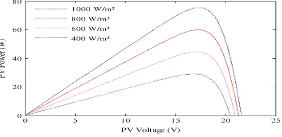
The above expressions show the characteristics of the PV module, which depends on the solar radiation S and the ambient temperature. As it can be seen from Figure 3, is the graph of PV power as a function of the voltage under a different irradiance at a constant ambient temperature. The property of the PV module is very pivotal for analyzers in the study of the PV system, mostly for maximum power point tracker (MPPT).
Figure 3. Characteristic of PV panel power curve.
3. MPPT Techniques
As we mentioned earlier, the efficiency of PV solar modules is so low. Therefore, it is necessary to specify the PV working point in the maximum power point of the PV curve. With the help of MPPT techniques, we achieve this task. There are different types of MPPT that are presented.
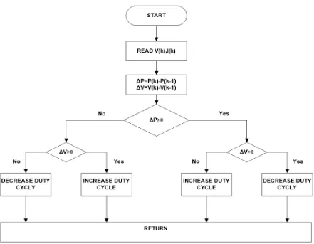
3.1. Perturb & observe (P&O)
Figure 4. Flow Char of Perturb and Observed Method
3.2. Constant voltage (CV)
The CV method operates on the stake that the voltage on MPP is about 85% of the open circuit voltages of the PV module in normal atmospheric conditions. The voltage at the terminal modules varies slightly even if the solar radiation changes. These changes occur when there is temperature change. It is proposed to use this method in the area where the temperature fluctuation is the lowest. It is very easy to implement this technique as a parameter to detect and can easily control the loop so that to reach the maximum power point [7].
3.3. Temperature effects on MPPT
One of the good choices is to use a method of temperature. In this technique, the PV array is senses temperature and therefore monitored by the MPP. An inexpensive temperature sensor has been used for this purpose and modifies the function of the MPP algorithm that supports the correct MPP path. But the problem is an irregular distribution of the temperature of the PV array. Additionally, if the sensor is not properly connected and may be misaligned. Then, it gives a wrong measure of PV temperature [8]. The equation of the temperature method is introduced in below.
𝑉𝑀𝑃𝑃(𝑡) = 𝑉𝑀𝑃𝑃(𝑇𝑟𝑒𝑓) + 𝑇𝑘𝑣𝑜𝑐(𝑇 − 𝑇𝑟𝑒𝑓) (6)
Where, VMPP is the voltage of MPP, Tref is the physically properties of the standard test condition
Tkvoc is coefficient of the temperature of VMPP, T is the temperature of the field.
3.4. Incremental Conductance
𝑑𝑃
𝑑𝑉=
𝑑(𝑉 ∗ 𝐼)
𝑑𝑉 = 𝐼 + 𝑉
𝑑𝐼
𝑑𝑉 (7)
∆𝐼
∆𝑉= −
𝐼
𝑉 (8)
∆𝐼
∆𝑉>
𝐼
𝑉 (9)
∆𝐼
∆𝑉<
𝐼
𝑉 (10)
ΔV - 0
ΔI/ΔV = -I/V ?
ΔI/ΔI > -I/V
ΔI – 0?
ΔI > 0?
INCREASE OPERATING
VOLTAGE
DECREASE OPEARTING VOLTAGE
INCREASE OPERATING
VOLTAGE
DECREASE OPEARTING VOLTAGE
RETURN START
No
No
No No
Yes
Yes
Yes Yes
Yes
No
Figure 5.Flow Chart of Incremental Conductance Method
3.5. Ripple Correlation control method
This system is supported on highest energy transfer principle. It is possible to find the best results by managing power via all pass filters. That means that the high frequency filter is utilizing to detect high frequency waves in power and voltage. The current mains Igrid is in part with the mains
voltage of Vgrid, which corresponds to the instantaneous power value cuts on the mains. It is given below.
𝑃𝑔𝑟𝑖𝑑(𝑡)= 𝑉𝑔𝑟𝑖𝑑 𝐼𝑔𝑟𝑖𝑑(1 + cos 2𝜔𝑡 ) (11)
From the equation above, the instantaneous power-pulsates at a frequency twice of that grid, current, power, and creating the ripple contained in the voltage PV. The ripple of the PV voltage and power are used to determine the direction of the MPPT. Comparing MPPT algorithms as benchmarking standards for performance measurements. These steps are primarily due to tracking factor (TF), dynamic behavior plus voltage ripple in MPP, price, number of sensors, and ease of execution. According to all the above criteria, the TF is valuable for the MPPT IC to be the highest TF, 98%. And IC MPPT performance is better in dynamic behavior.
Power electronics play a leading role in the PV system for converting solar energy. The DC-DC converter is a special electronic device that converts an electrical DC source from a voltage level to the prescribed voltage level. The DC-DC electronic converters are the focus of MPPT system for PV applications [10]. A DC-DC converter operation forms the basis for MPP detection in accordance with the proposed MPPT global control algorithm. In practice, the voltage output of the photoelectric signal cable is very small, despite the use of MPPT. It requires that a DC - DC converter that uses the initial end of the network's access capability. The most common topics for DC-AC and DC-DC electronic converters are shown in the schematic diagram of the grid connected to the PV shown in the Figure 6. The unregulated DC voltage is tuned and converted to the desired AC signal using an inverter. The AC signal connected to the network after the EMI filter.
Figure 6.Block Diagram of Grid Connected Solar PV System
DC-DC converters are described in the literature as having multiple topologies that divided into two batches non-isolated and isolated topologies. Non- isolated has no transformer output and is often used if they have low voltage control. The most common topologies are DC - DC converter in PV systems, such as buck and buck-boost converters. The potential of any topology represents in the following sections such as boundary filter inductance (Lb), voltage gain (Av), Input impedance (Ri), current gain (Ai) [11]. A converter can work in two different ways: continuous conductivity and discontinuous conductivity. And among two continuous conductivity is suitable for the solar PV application. [12]. The Figure 7 is a two-stage topological diagram of DC - DC boost converter. A DC-DC boost converter connects and adjusts the output voltage of the photoelectricity and MPPT circuitry. An adjustable DC voltage of the PV solar energy is then converted by a DC to AC inverter into the desired frequency AC signal. Further, the DC-AC inverter connects the grid network with an EMI filter. The connection of this grid network has several functions. This topology is useful when the output voltage of solar radiation is less.
V
gI
DS
R
I
o+
-D
V
L+
-C
L
I
LI
g+
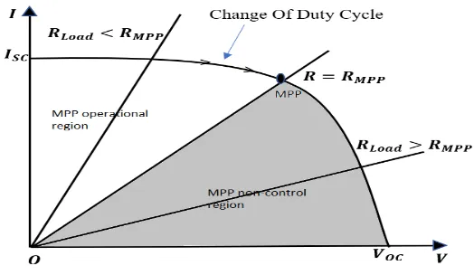
Figure 7-A. operational and non-operational regions of Current- Voltage curve of boost converter Performance parameters of the boost converter are indicated in Table 1. The boost converter only works with RLoad < RMPP. The operational and non-operational region of current and voltage curve of
PV are shown in Figure 7-A; The boost converter does not follow the points near open circuit voltage. It is possible that the output voltage of the PV solar energy increases or decreases according to the environmental conditions. In both cases, electronic converters must control the output voltage. For this purpose, a DC-DC converter is used before a full-bridge DC-AC converter. In a buck- boost converter, the output voltage is lower or higher than the input voltage. This topology could be obtained by cascading a Buck-boost converter. In the Buck-boost converter, the input ampere is interrupted [12]. Due to lack of this coordination, there is a ripple and high voltage input power that limits switching [11]. Figure 8 shows a two-phase topological scheme with a DC-DC buck- boost PV converter. This DC-DC converter can accelerate or reduce the voltage as needed.
V
gI
LS
R
I
o +-V
L +-C
I
gL
D
+
-Figure 8. Circuit Diagram of Buck- Boost Converter
Figure 8-A. operational regions of Current- Voltage curve of buck- boost converter
operating voltage moves in the left side of the current-voltage curve and a decrease in the D and there is an increase in the input resistance so that the operating voltage moves to the right of the Current-Voltage curve. Unlike the boost converter, the buck-boost converter is expected to operate in both regions.
Table 1. Performance Parameter for Dc-Dc Converters
Components Performance Parameters
𝑨𝒊= 𝑰𝟎
𝑰𝒔 𝑹𝒊=
𝑽𝒔
𝑰𝒔 𝑨𝒗=
𝑽𝟎
𝑽𝒔
Lb Cmin
Boost
𝟏 − 𝑫 (𝟏 − 𝑫)𝟐𝑹𝑳 𝟏
𝟏 − 𝑫
(𝟏 − 𝑫)𝟐
𝟐𝒇 𝑫𝑹𝑳
𝑫
𝑽𝒓𝑹𝑳𝒇
𝑽𝟎
Buck- Boost
Converter 𝟏 − 𝑫 𝑫
(𝟏 − 𝑫)𝟐
𝑫𝟐 𝑹𝑳
𝟏 𝟏 − 𝑫
(𝟏 − 𝑫)𝟐
𝟐𝒇 𝑹𝑳
𝑫
𝑽𝒓𝑹𝑳𝒇𝑽𝟎
Ri = Input impedance of converter; D: duty cycle; f: switching frequency; RL: load impedance; Vr = output
ripple voltage: V0: output voltage
5. Dc–Ac Converter
PV
T1
T2 T3
T4 T5
L1
L2
Vgrid A
B
Cdc
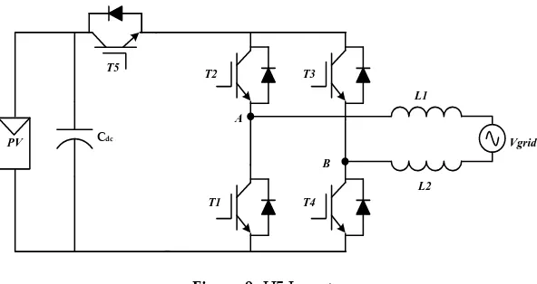
Figure 9.H5 Inverter
A highly efficient and reliable inverter concept (HERIC) has been developed by connecting two additional switches in the full bridge converter with the AC outlet side. Each diagonal switch operates on a high-frequency switch to the network voltage [13]. Figure 10 represent the connection diagram of the HERIC topology. In the HERIC topology, a parallel branch is combined with an output filter and offers the benefits of high efficiency and a reduced leakage current [14]. The output voltage of three levels with a unipolar PWM output with a low cross filter wave. The efficiency of the inverter has dramatically increased, without compromising the overall performance of the system. Since no normal voltage is formed, the leakage current due to parasitic capitalization is very small. The HERIC topology provides very high conversion efficiency in a large work environment compared to other topologies. The use of bidirectional switches changes the frequency of network losses relative to another topology. Based on network fault topology and network support services for the PV systems, the low-voltage traversal capability of the HERIC is in the study [15].
T5
B A
L2 T1
PV
L1 T3
Cdc
T2 T6
T4
Vgrid
Figure 10. Heric Inverter
6. Filter
A filter comprises of inductance and capacitance that is used in between the inverter and the grid. The filter reduces the higher order harmonics introduced by the PWM modulation of the DC - AC converter [21]. The LCL filter design has the grid side inductance (Lg) and a capacitance (Cf), It’s
considered as second order low pass filter, and inverter side inductance (Li). The ratio of the
inductance of the grid side and the inductance of the converter side depends on the current attenuation of the ripple [22].
𝐿𝑖= 𝑉𝑔
2√6 𝑓𝑠𝐼𝑟𝑖𝑝𝑝𝑙𝑒.𝑝𝑒𝑎𝑘
(12)
𝐶𝑓 =
0.05
ω𝑛𝑍𝑏𝑎𝑠𝑒
(13)
𝑍𝑏𝑎𝑠𝑒 =
𝑉2
𝑔𝐿𝐿
𝑃𝑛
where Vg is the R.M.S voltage of grid. Phase voltage; fs is the switching frequency of inverter; I
ripple, peak represents the peak value of ripple current; Pn is the rated power of the inverter; VgLL is
the grid line of voltage; ωn is the operating frequency. In reference [23] authors recommend a control
structure based on a proportional resonance (PR) controller connected to the PV through LCL filter with zero error in the solid state and the selection of harmonic compensation.
7. Stability Analysis of The Solar PV
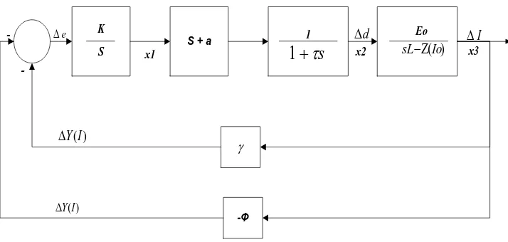
The modeling system and its stability analysis are an important research area. The modeling of the PV solar energy transformation system is a very composite mission for analyzers, because it’s a complicated model. As we discuss before, it includes converters of power electronics, PV solar power, control algorithm and MPPT techniques. An analyzer has been proposed by several models and methods for analyzing stability. Provides simulation and control of a solar PV system, as well as a DC- DC boost converter and MPPT incremental conductivity in [18]. The analyzer made a model for the state space and offered a third order. A block diagram of a small signal model is represented in Figure 11. This control unit in the solar PV contains a two-dimensional diode of polycrystalline cells. It doesn’t contain a partial shadow effect.
S + a
-Φ
K
S
1 Eo
x2 x1
-K
x3
) (I Y
) (I Y
s
+
1
sL−(Io)I
d
e
Figure 11. Signal Model Control Block Diagram
The moderate-boost converter model is included, and the transfer function is derived. D is the converter of the duty cycle in this control diagram. The K parameter is the PI controller, so MPPT shows an error. 𝜏 is the time constant of the low pass filter used to eliminate the frequency of the control signals. The diagram of the boost transfer function is connected to points d and I.
The states of the system are shown in x1, x2, x3. The y -Φ plot is a unique combination of conductivity. The model is tested for changes in the working cycle phase.
8. Trending of The System
(ST). This trend prevents integration and full use of PV energy and storage elements, saving additional power converters and increasing overall efficiency and energy security.
9. Future cost estimation of PV system:
Over the past few years, the price of PV modules has decreased significantly. In addition, the price of PV inverters also followed a trend like that of PV modules. In accordance with the date of the contract and type of application, installation costs are reduced at different rates. Nevertheless, prices for several elements of PV systems have not fallen to the same rate. The presentation and fiscal research of electronic power devices used in solar PV systems were represented in [19]. A comprehensive study describing the current state of development of the use of photoelectric solar energy in the world and its untapped potential and growth prospects for the next few years have been presented in [20]. Figure 12 shows a rough estimate of the total cost of PV energy systems for energy production per kilowatt. The x axis indicates the years, and the y axis represents the cost of PV solar systems in USD / kW. It is evaluated that the cost of PV systems in 2050 will be reduced by 75%.
Figure 12. Evolution of Prices of Large PV System
10. Implementation of hardware
The proposed Research work is implemented in real time. The actual interface is shown in following Figure 13 Energy stored in the battery is fed to the conversion system, where various MPPT algorithms are tested for optimum point of operation and fed to the voltage controller.
The results are displayed on the LED display. One can identify the performance from this.
3100
1650
1450
1210
1050
975 910 850
825
2800
1580
1025
875 775
725 675 650 640
0 500 1000 1500 2000 2500 3000 3500
2010 2015 2020 2025 2030 2035 2040 2045 2050
Figure 13. Circuitry of Real Time Hardware Implementation
11. Conclusions
The goal of our work has been achieved by giving a detailed description of the research ranges for a single-phase solar PV energy conversion system. It presents a detailed study of the components of solar PV systems, such as solar cells, PV panels, MPPT and filters. Several types of DC-DC converters have been developed to increase the output voltage of solar photoelectric energy. Their comparative studies are presented. Various MPPT algorithms are discussed and their advantages and complexities are discussed. Stability analysis, which followed the structure of the integrated converter module, filter operation and parts of the future research are discussed in all these areas. At the end of the article, general characteristics of PV systems, cost estimates and prospects for future research in the field of integration of solar energy grid are presented.
Author Contributions: This paper was a collaboration effort among all authors. All authors are conceived the methodology, conducted the experiment tests, and wrote the paper. R.A.R analyzed, designed and development of the experiment methodologies, J.D and K.V.G.R supported the work to perform in real time and, H.J.KIM verified the overall experiment.
Funding: This research experiment was supported by BK21PLUS, Creative Human Resource Development Program for IT Convergence.
Acknowledgments: This research experiment was supported by Brain Korea 21 Center for Creative Human Resource Development Program for IT Convergence of Pusan National University.
Conflicts of Interest:“The authors declare no conflict of interest.”
References
1. Solanki, C.S. Solar Photovoltaic- Fundamentals, Technologies and Applications, 3rd ed.; PHI Learning: New Delhi, India, 2012; pp. 3–22, ISBN 9788120351110.
2. Gilbert, M. M. Renewable and efficient electric power systems, 2nd ed.; John Wiley & Sons, Inc: Hoboken, New Jersey, USA, 2013; pp. 253–301, ISBN 9781118633502
3. Mahesh, B.; Henry, B. Signal Processing for Solar Array Monitoring, Fault Detection, and Optimization, Morgan & Claypool, Morgan & Claypool Publishers, 2012; pp.1-95, ISBN 9781608459490.
4. Fangrui, L.; Yong, K.; Yu, Z. Comparison of P&O and hill climbing MPPT methods for grid-connected PV converter.3rd IEEE Conference on Industrial Electronics and Application, Singapore, 3-5 June 2008; IEEE 5. Hadi, M.; Yang, C. BICO MPPT: A faster maximum power point tracker and its application for photovoltaic panels.
6. Elobaid, L.M.; Abdelsalam, A. K.; Zakzouk, E.E. Artificial neural network based maximum power point tracking technique for PV systems. 38th Annual Conference on IEEE Industrial Electronics Society, Montreal, QC, Canada, 25-28 Oct. 2012; IEEE.
7. Moacyr Aureliano, G. Db.; Luigi, G.; Leonardo, P.M. Evaluation of The Main MPPT Techniques for Photovoltaic Applications. IEEE Transaction on Industrial Electronics 2013, 60, 1156-1167, http://dx.doi.org/10.1109/TIE.2012.2198036.
8. Roberto, F.C.; Filipe, M.C.; Denizar, C.M. A MPPT Approach Based on Temperature Measurement Applied in PV Systems. 2010 9th IEEE/IAA International Conference on Industry Application- Induscon 2010, Sao Paulo, Brazil, 8-10 November 2010; IEEE.
9. Kante, V. An Investigation of Incremental Conductance Based Maximum Power Point Tracking for Photovoltaic System. Energy Procedia 2014, 54, pp. 11–20, https://doi.org/10.1016/j.egypro.2014.07.245.
10. Gaikwad, D.D.; Chavan, M.S.; Gaikwad, M.S. Hardware Implementation of Dc-Dc Converter for MPPT PV Applications. 2014 IEEE Global Conference on Wireless Computing and Networking, Lonavala, India, 22-24 Dec. 2014; IEEE.
11. Farahat, M. A.; Metwally, H.M.B.; Ahmed Abd-Elfatah, M. Optimal Choice and Design of Different Topologies of Dc-Dc Converter Used in PV Systems, At Different Climatic Conditions in Egypt. Renewable Energy 2012, 43, 393-402, https://doi.org/10.1016/j.renene.2011.10.021.
12. Duran, E.; Andujar, J.; Segura, F. A High-Flexibility DC Load For Fuel Cell and Solar Arrays Power Sources
Based on Dc - Dc Converters. Applied energy 2011, 88, 1690-1702,
https://doi.org/10.1016/j.apenergy.2010.11.002
13. David, G.P.; Edison, G.E.; Javier, R.F. Implementation A HERIC Inverter Prototype Connected to The Grid Controlled By SOGI-FLL. 2015 IEEE Workshop on Power Electronics and Power Quality Applications; Bogota, Colombia, 2-4 June 2015; IEEE.
14. Phan, Q.D.; Dao, N.D.; Nguyen, B.A. Design of HERIC Inverter for PV Systems by Using Hardware in The Loop (Hil) Concept. 2014 IEEE 9th Conference on Industrial Electronics and Applications, Hangzhou, China, 9-11 June 2014, IEEE.
15. Yongheng, Y.; Frede, B.; Huai, W. Low-Voltage Ride-Through of Single-Phase TransformerLess Photovoltaic
Inverters. IEEE Transactions on Industry Application 2014, 50, 1942-1952,
https://doi.org/10.1109/TIA.2013.2282966
16. Huafeng, X.; Shaojun, X.; Yang, C. An Optimized Transformer Less Photovoltaic Grid Connected Inverter. IEEE Transaction on Industrial Electronics 2011, 58, 1887-95, https://doi.org/10.1109/TIE.2010.2054056.
17. Stefanos, S.; Eftichios, K.; Frede, B. Optimization of Sic-Based H5 And Conergy-NPC Transformer Less PV Inverters. IEEE Journal of Emerging and Selected Topic in Power Electronics 2015, 3, 555-567, https://doi.org/10.1109/JESTPE.2014.2332253.
18. Kish, G. J.; Lee, J. J.; Lehn, P.W. Modelling and Control of Photovoltaic Panels Utilizing the Incremental Conductance Method for The Maximum Power Point Tracking. IET Renewable Power Generation 2012, 6, 259-266, https://doi.org/10.1049/iet-rpg.2011.0052.
19. Deline, C.; Marion, B. A performance and economic analysis of distributed power electronics in photovoltaic systems. Natl Renew Energy Lab NREL/TP-5200- 50003 2011:1–20.
20. Solar generation; Solar photovoltaic electricity empowering the world. European Photovoltaic Industry Association Solar Generation 6 2011; pp. 1–110.
21. Roberto, Z.; Stefania, C. Power control of grid-connected photovoltaic systems. 2011 IEEE International Symposium on Industrial Electronics, Gdansk, Poland, 27-30 June 2011; IEEE
22. Ravi, N.T.; Alka, S.; Tsuyoshi, H. Design and Control of LCL Filter Interfaced Grid Connected Solar Photovoltaic (SPV) System Using Power Balance Theory. International Journal of Electrical Power And Energy Systems 2015, 69, 264-272, https://doi.org/10.1016/j.ijepes.2015.01.018.