ISSN (Print) : 2320 – 3765 ISSN (Online): 2278 – 8875
I
nternational
J
ournal of
A
dvanced
R
esearch in
E
lectrical,
E
lectronics and
I
nstrumentation
E
ngineering
(An ISO 3297: 2007 Certified Organization) Vol. 3, Issue 12, December 2014
PV Systems Based DC-DC Converters for
Different MPPT Algorithms
Harinee.K
1, S.Krishnan
*2, Dr. M. Venugopala Rao
3Assistant Professor, Dept. of EEE, Jerusalem College of Engineering, Chennai, Tamil Nadu, India1 Assistant Professor, Dept. of EEE, Bharath University, Chennai, Tamil Nadu, India2 Associate Professor, Dept. of EEE, Bharath University, Chennai, Tamil Nadu, India3 * Corresponding Author
ABSTRACT: The comparative study between two most popular algorithms technique which is incremental conductance algorithm and perturbs and observe algorithm. Two different converters buck and boost converter use for comparative in this study. Few comparison such as voltage, current and power output for each different combination has been recorded.MATLAB Simulink tools have been used for performance evaluation on energy point.
KEYWORDS: Maximum power point tracking (MPPT), Photovoltaic (PV), Direct current (DC), Converter, Efficiency.
I. INTRODUCTION
The rapid increase in the demand for electricity and the recent change in the environmental conditions such as global warming led to a need for a new source of energy that is cheaper and sustainable with less carbon emissions. Solar energy has offered promising results in the quest of finding the solution to the problem. The harnessing of solar energy using PV modules comes with its own problems that arise from the change in insulation conditions. These changes in insulation conditions severely affect the efficiency and output power of the PV modules[1,3].A great deal of research has been done to improve the efficiency of the PV modules. A number of methods of how to track the maximum power point of a PV module have been proposed to solve the problem of efficiency and products using these methods have been manufactured and are now commercially available for consumers [1,3]. As the market is now flooded with varieties of these MPPT that are meant to improve the efficiency of PV modules under various insolation conditions it is not known how many of these can really deliver on their promise under a variety of field conditions. This research then looks at how a different type of converter affects the output power of the module and also investigates if the MPPT that are said to be highly efficient and do track the true maximum power point under the various conditions [1,3].
A MPPT is used for extracting the maximum power from the solar PV module and transferring that power to the load [4, 5]. A dc/dc converter (step up/ step down) serves the purpose of transferring maximum power from the solar PV module to the load. A dc/dc converter acts as an interface between the load and the module shown in Fig 1. By changing the duty cycle the load impedance as seen by the source is varied and matched at the point of the peak power with the source so as to transfer the maximum power [5].
ISSN (Print) : 2320 – 3765 ISSN (Online): 2278 – 8875
I
nternational
J
ournal of
A
dvanced
R
esearch in
E
lectrical,
E
lectronics and
I
nstrumentation
E
ngineering
(An ISO 3297: 2007 Certified Organization) Vol. 3, Issue 12, December 2014
Fig.1 DC – DC converter for operation at the MPP
Few comparison such as voltage, current and power output for each different combination has been recorded. Multi changes in duty cycle, irradiance, temperature by keeping voltage and current as main sensed parameter been done in the simulation. The MPPT techniques will be compared, by using MATLAB tool Simulink, considering the variant of circuit combination.
This paper is organized as follows: Section I gives the Introduction to the MPP Techniques. Section II gives the PV array introduction. Section III gives the DC-DC Converter Information. Section IV gives the Problem Overview. Section V gives the MPPT algorithms and Section VI and VII give the results and the conclusion respectively.
II. PV ARRAY
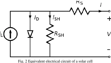
A solar panel cell basically is a p-n semiconductor junction. When exposed to the light, a DC current is generated. The generated current varies linearly with the solar irradiance [8] [14]. The equivalent electrical circuit of an ideal solar cell can be treated as a current source parallel with a diode shown in Fig 2.
Fig. 2 Equivalent electrical circuit of a solar cell
The I-V characteristics of the equivalent solar cell circuit can be determined by following equations . The current through diode is given by:
ID = I [ exp (q(V + I RS)/KT)) – 1] (1)
I = IL – ID – Ish (2)
I = IL – I [ exp (q(V + I RS)/KT)) – 1] – ( V + IRS )/ Rsh (3)
Where:
I : Solar cell current (A)
ISSN (Print) : 2320 – 3765 ISSN (Online): 2278 – 8875
I
nternational
J
ournal of
A
dvanced
R
esearch in
E
lectrical,
E
lectronics and
I
nstrumentation
E
ngineering
(An ISO 3297: 2007 Certified Organization) Vol. 3, Issue 12, December 2014
ID: Diode saturation current (A) q : Electron charge (1.6×10⁻¹⁹ C) K : Boltzman constant (1.38×10⁻²³ J/K) T : Cell temperature in Kelvin (K) V : solar cell output voltage (V) Rs: Solar cell series resistance (Ω) Rsh: Solar cell shunt resistance (Ω)
II. DC-DC CONVERTER
A.Buck Converter
The buck converter can be found in the literature as the step down converter [15,16]. This gives a hint of its typical application of converting its input voltage into a lower output voltage, where the conversion ratio M = Vo/Vi varies with the duty ratio D of the switch [15]. An ideal buck converter is shown in Fig 3.
Fig. 3: Ideal buck converter circuit
B.Boost Converter
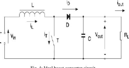
The boost converter is also known as the step-up converter. The name implies its typically application of converting a low input-voltage to a high out-put voltage, essentially functioning like a reversed buck converter [13] [16]. An ideal boost converter is shown in Fig 4.
Fig. 4: Ideal boost converter circuit
III. SIMULATION RESULTS
All simulation and result for every converter have been recorded to make sure the comparison of the circuit can be determined accurately [11] [17]. The input, output, voltage, current and power is the main comparison to take into consideration.. Convergence speed, hardware required and range of effectiveness. Fig.5 take an insolation of 100 and temperature 50 as initial value.
ISSN (Print) : 2320 – 3765 ISSN (Online): 2278 – 8875
I
nternational
J
ournal of
A
dvanced
R
esearch in
E
lectrical,
E
lectronics and
I
nstrumentation
E
ngineering
(An ISO 3297: 2007 Certified Organization) Vol. 3, Issue 12, December 2014
Fig. 5: Output Voltage, Current and Power for PV panel
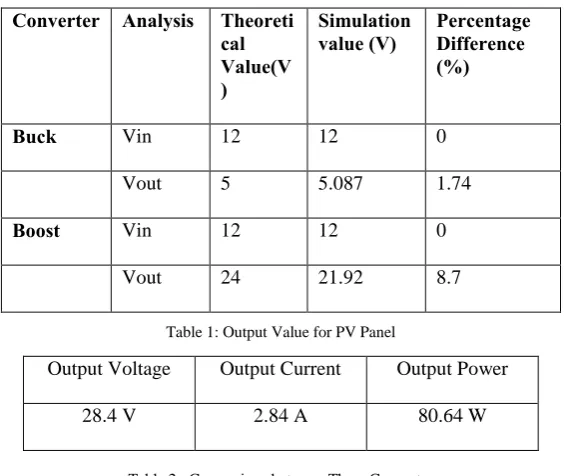
Table 1: Output Value for PV Panel
Table 2 : Comparison between Three Converter in Theoretical and Simulation Value
Result for insolation = 100 and temperature = 48o
From table 2 calculate theoretical result and simulation result can be observe. The percentage between theoretical value and experimental value also can be seen from the simulation output. All three simulations give difference type of curve [20]. Theoretical value calculated from the basic equation of converters.
Converter Analysis Theoreti
cal Value(V )
Simulation
value (V) Percentage Difference (%)
Buck Vin 12 12 0
Vout 5 5.087 1.74
Boost Vin 12 12 0
Vout 24 21.92 8.7
Output Voltage Output Current Output Power
ISSN (Print) : 2320 – 3765 ISSN (Online): 2278 – 8875
I
nternational
J
ournal of
A
dvanced
R
esearch in
E
lectrical,
E
lectronics and
I
nstrumentation
E
ngineering
(An ISO 3297: 2007 Certified Organization) Vol. 3, Issue 12, December 2014
B Buck Converter Simulation With Perturb and Observe Controller
Fig 6: Output current and voltage for Buck and P&O Controller
C Buck Converter Simulation With Incremental Cond.Controller
Fig 6: Output current and voltage for Buck and In Con Controller
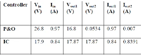
Buck the connected with P&O give a value of 26.8 V therefore buck that connected with incremental conductance give value of 17.87V shown in Table 3. In Incremental Conductance controller the output voltage and current is not change between input and output value [18]. The Perturb and Observe Controller give a difference for input and output value. The output value behave as Buck converter behave. The voltage will drop from 26.8V to 16.8V and finally the voltage value is 534mV. In this system show that incremental conductance controller will work better with buck controller than perturb and observe controller. The incremental conductance controller will have the stable value from start to end of the simulation [19].
ISSN (Print) : 2320 – 3765 ISSN (Online): 2278 – 8875
I
nternational
J
ournal of
A
dvanced
R
esearch in
E
lectrical,
E
lectronics and
I
nstrumentation
E
ngineering
(An ISO 3297: 2007 Certified Organization) Vol. 3, Issue 12, December 2014
D Boost Converter Simulation With P&O Controller
Fig 7: Output current and voltage for Boost and P&O Controller
E Boost Converter Simulation With Incremental ConditionController
Fig 8: Output current and voltage for Boost and IC Controller
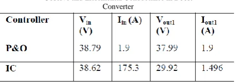
Table 4: Comparison Output Value Between Perturb & Observe and Incremental Conductance in Boost
Converter
ISSN (Print) : 2320 – 3765 ISSN (Online): 2278 – 8875
I
nternational
J
ournal of
A
dvanced
R
esearch in
E
lectrical,
E
lectronics and
I
nstrumentation
E
ngineering
(An ISO 3297: 2007 Certified Organization) Vol. 3, Issue 12, December 2014
IV. CONCLUSION
This paper has presented a comparison of two most popular MPPT controllers, Perturb and Observe Controller with Incremental Conductance Controller. This paper focus on comparison of two different converters which will connect with the controller. Solar panel has been included in the simulation circuit. From all the cases, the best controller for MPPT is incremental conductance controller. This controller gives a better output value for buck and boost converter In simulation Buck converter shows better performance. The controller work at the best condition using buck controller.
REFERENCES
1. R. S.Lewis, "Antartic Research and Relevant of Science," in Bulletin of the Atomic Scientists, vol. 26, 1970, pp. 2.
2. Y.-H. Chang and C.-Y. Chang, "A Maximum Power Point Tracking of PV System by Scaling Fuzzy Control," presented at International Multi Conference of Engineers and Computer Scientists,Hong Kong, 2010.
3. Babu T.A., Sharmila V., "Cefotaxime-induced near-fatal anaphylaxis in a neonate: A case report and review of literature", Indian Journal of Pharmacology, ISSN : 0253-7613, 43(5) (2011) pp.611-612.
4. S.Mekhilef, "Performance of grid connected inverter with maximumpower point tracker and power factor control,"International Journal of Power Electronics, vol. 1, pp. 49-62, 2008.
5. M.E.Ahmad and S.Mekhilef, "Design and Implementation of a Multi Level Three-Phase Inverter with Less Switches and Low Output Voltage Distortation," Journal of Power Electronics, vol.9,pp. 594-604, 2009.
6. Valiathan G.M., Thenumgal S.J., Jayaraman B., Palaniyandi A., Ramkumar H., Jayakumar K., Bhaskaran S., Ramanathan A., "Common docking domain mutation e322k of the erk2 gene is infrequent in oral squamous cell carcinomas", Asian Pacific Journal of Cancer Prevention, ISSN : 1513-7368, 13(12) (2012) pp.6155-6157.
7. S. Chin, J. Gadson, and K. Nordstrom, "Maximum Power Point Tracker," Tufts University Department of Electrical Engineering and Computer Science,2003, pp.1-66.
8. R. Faranda and S. Leva, "Energy Comparison of MPPT techniques for PV Systems," WSES Transaction on Power Systems,vol. 3, pp. 446-455, 2008.
9. Mani Sundar N., Krishnan V., Krishnaraj S., Hemalatha V.T., Alam M.N., 'Comparison of the salivary and the serum nitric oxide levels in chronic and aggressive periodontitis: A biochemical study", Journal of Clinical and Diagnostic Research, ISSN : ISSN - 0973 - 709X, 7(6) (2013) pp.1223-1227.
10. Vikrant.A.Chaudhari, "Automatic Peak Power Traker for Solar PV Modules Using dSpacer Software.," in Maulana Azad National Institute Of Technologyvol. Degree of Master of Technology In Energy. Bhopal: Deemed University, 2005, pp. 98.
11. T. P. Nguyen, "Solar Panel Maximum Power Point Tracker," in Department of Computer Science & Electrical Engineering:University of Queensland, 2001, pp. 64.
12. Thirunavukkarasu A.B., Chandrasekaran V., 'Efficacy of anti-scorpion venom serum over prazosin in severe scorpion envenomation: Is the current evidence enough", Journal of Postgraduate Medicine, ISSN : 0022-3859, 57(1) (2011) pp.83-84.
13. B. S, Thansoe, N. A, R. G, K. A.S., and L. C. J., "The Study and Evaluation of Maximum Power Point Tracking Systems," International Conference on Energy and Environment 2006 (ICEE2006), pp. 17-22, 2006.
14. C. S. Lee, " A Residential DC Distribution System with Photovoltaic Array Integration.," vol. Degree of Honors Baccalaureate of Science in Electrical and Electronics Engineering, 2008, pp. 38.
15. Subbaraj G.K., Kulanthaivel L., Rajendran R., Veerabathiran R., "Ethanolic extract of Carum carvi (EECC) prevents N-nitrosodiethylamine induced phenobarbital promoted hepatocarcinogenesis by modulating antioxidant enzymes", International Journal of Pharmacy and Pharmaceutical Sciences, ISSN : 0975 - 1491, 5(S1) (2013) pp.195-199.
16. T. Esram and P. L.Chapman, "Comparison of Photovoltaic Array Maximum Power Point Tracking Techniques," in 9. Urbana.
17. E. I and O. Rivera, "Maximum Power Point Tracking using the Optimal Duty Ratio for DC-DC Converters and Load Matching in Photovoltaic Applications," IEEE, pp. 987-991, 2008.
18. G. Adamidis, P. Bakas, and A. Balouktsis, "Photovoltaic System MPPTracker Implementation using DSP engine and buck – boost DC- DC converter."
19. M. Azab, "A New Maximum Power Point Tracking for Photovoltaic Systems," in WASET.ORG, vol. 34, 2008, pp. 571-574.
20. H. Knopf, "Analysis, Simulation, And Evaluation of Maximum Power Point Tracking (MPPT) Methods for a solar power vehicle," in Electrical and Computer Engineering, vol. Master of Science in Electrical and Computer Engineering: Portland State University 1999, pp. 177.
21. T.S.USTUN and S. Mekhilef, "Effects of a Static Synchronous Series Compensator (SSSC) Based on Soft Switching 48 Pulse PWM Inverter on the Power Demand from the Grid," Journal of Power Electronics, vol. 10, pp. 85-90, 2010.
22. A. Oi,"Design and Simulation of Photovoltaic Water Pumping System," in Electrical Engineering, vol. Master of Science in Electrical Engineering. San Luis Obispo: California Polytechnic State University, 2005, pp. 113.
23. B Karthik, TVUK Kumar, Authentication Verification and Remote Digital Signing Based on Embedded Arm (LPC2378) Platform, World Applied Sciences Journal 19 (9), 1146-1149, 2014.
24. Shriram, Revati; Sundhararajan, M; Daimiwal, Nivedita; , Effect of change in intensity of infrared LED on a photoplethysmogramIEEE Communications and Signal Processing (ICCSP), 2014 International Conference on, PP 1064-1067,2014.
25. Daimiwal, Nivedita; Sundhararajan, M; , Functional MRI Study for Eye Blinking and Finger Tapping.
26. Daimiwal, Nivedita; Sundhararajan, M; Shriram, Revati; , Respiratory rate, heart rate and continuous measurement of BP using PPGIEEE Communications and Signal Processing (ICCSP), 2014 International Conference on, PP 999-10022014.
27. Daimiwal, Nivedita; Sundhararajan, M; Shriram, Revati; , Non Invasive FNIR and FMRI system for Brain Mapping.