- 256 - Abstract— A Switched Reluctance Motor (SRM) has several desirable features, including simple construction, high reliability and low cost. However, it suffers from large torque ripple and large noise. In addition, highly non-uniform torque output and magnetization characteristics lead to complication of the control system. Several studies have succeeded in torque ripple reduction for SRM using Direct Torque Control (DTC) technique. Compared to conventional methods including voltage control and current chopping mode control, DTC method has many advantages such as simple algorithm, less torque ripple and instantaneous response to the torque command. In this paper, DTC of a 5 phase 10/8 SR motor is proposed. Performance of the motor is studied through the computer simulation in Matlab/Simulink. The simulation results are compared to corresponding results of the same motor, controlled by hysteresis band method. The comparison results show that the proposed method results in a remarkable reduction in torque ripple for all levels of the motor torque without enforcing any drawbacks to the system performance, even in the transient conditions.
Index Terms— Direct Torque Control, Switched Reluctance Motor, Fuzzy Control Method, Torque Ripple
I. INTRODUCTION
A Switched Reluctance Motor (SRM) has numerous advantages over other types of AC machines due to its simple and solid construction. The rotor has a simple laminated structure with no permanent magnets or rotor windings. It rotates by using the reluctance torque, produced from magnetic saliency between stator poles and rotor poles. Thus, SRM can operate at high speeds and it is suitable for applications in high-temperature and hazardous environments. In addition, SRM has enough high efficiency as compared with permanent magnet motors because it also needs no secondary windings. On the other hand, its large torque ripple and high noise level caused by its doubly salient structure restrict its wide application in the industry. Additionally, the highly nonlinear magnetic characteristics of the motor make the control of the motor intricate. This is further complicated by the interaction due to mutual coupling of motor phases and parameters variation of the inductance characteristics [1-2].
The previous works can be split into two main groups including the works which used the linear model of the motor
Manuscript received April 14, 2009.
M. Reza Feyzi is with Electrical Engineering Department, Tabriz University, Tabriz, Iran.
Yousef Ebrahimi is with National Iranian gas company (NIGC), Dist. 8, Tabriz University, Tabriz, Iran.
Mahdi Zeinali is with Electrical Engineering Department, Sahand University of Technology, Tabriz, Iran.
with ignoring the saturation [3-6] and the works that implemented nonlinear models taking the motor saturation into account [7-9]. Taylor [3] used an adaptive feedback linearising controller for the SRM considering a linear magnetic circuit. Nagel et. al. proposed an analytical solution in order to produce a voltage profile that provides a smooth motor torque [4]; they assumed a linear torque characteristic for the motor. In their works, Matsui and Ma [5, 6] expressed the inductance of the motor as a simple sinusoidal function varying with position. Highly simplified models of a motor with the highly nonlinear torque and magnetization characteristics cause inaccuracy in most practical drives in the references above.
Ilic'-Spong et. al. [7] proposed a feedback linearising control method compensating the magnetic nonlinearities of the motor. This method needs exact knowledge of the motor parameters, so it is difficult to be implemented as a practical drive. In order to obtain a smooth torque Wallace and Stankovic [8, 9] generated such a current profile that enables the torque sharing between two phases. However, it requires a complex current waveform that imposes a time consuming computation making the control system too complicated for real-time implementation.
In general, voltage or current command profile is used in different aspects of SRM such as torque, speed or position control and even for torque ripple reduction. Using DTC, Jinupun [10] succeeded in torque ripple reduction of SR motors. He used a new type of winding configuration and applied the concept of short flux pattern that links two separate poles of the stator. However, the need for special motor winding configuration is both expensive and inconvenient. Cheok et. al. [11] applied DTC method to a 3-phase 6/4 SRM with a very close concept to that of conventional DTC of ac machines. They introduced a comparable theory with conventional DTC of ac machines by using motor flux and torque equations. In this method no winding configuration changing is required.
Motors with low phase number usually produce notably high torque ripple, Chan and Bolton [12]. As the number of poles increases, one can expect reduction on the developed torque ripple. At the same time, it imposes some disadvantages on other performance criteria which should be noticed. If in two SRM with different pole numbers, the iron to air ratio and excitation ampere-turn assumed to be constant, in order to achieve high inductance, flux density and total torque/weight ratio, the motor with the fewer pole number is preferable.
In this work, DTC method is applied to a 5-phase 10/8 SRM, where a significant modification should be exerted on mentioned method in [11]. This occurs due to difference of
M. Reza Feyzi, Yousef Ebrahimi and Mahdi Zeinali
- 257 - poles and phases number of two 6/4 and 10/8 motors.
II. MAIN CONCEPTS OF DTCMETHOD IN THE 5-PHASE SRM [11] is a comprehensive reference to perceive DTC scheme in 3-phase 6/4 SRM. Detailed illustrations have been proposed about the electromagnetic torque extraction by using the energy concept instead of co-energy, the stator flux calculation, the voltage space vectors definition and their relation with motor torque and flux control. The power converter configurations, its operation in different states of the switching elements and the voltage space vectors formation then have been presented for 3-phase 6/4 SRM. In the present paper mentioned concepts are expanded for a 5-phase 10/8 SRM summarily.
A. Flux Equation and Stator Flux Vector
It is essential to study the machine defining equations in order to extracting of DTC method. The stator flux linkage vector can be expressed as
0( )
t
s vs R iS s so
ϕ =
∫
− +ϕ(1) where ϕs
= stator flux vector component, v = stator voltage vector component, i = stator current vector component, R= stator resistance and ϕs0
= initial value of the stator flux vector. Except at the low voltage levels, the voltage drop through the stator resistance is negligible and therefore, from (1):
s
d v dt
ϕ ≈
(2) If the time interval is small enough, then (2) can be written as
s v t
ϕ
∆ = ∆ (3)
This shows that, in order to control of the variation of the stator flux, the voltage space vectors can be utilized. The applied voltage vector produces a stator flux variation which is in the same direction as the voltage vector. Magnitude of the variation is proportional to the voltage vector magnitude and∆t. As a result, one of the two basic principles of DTC in SRM is:
The stator flux linkage vector of the motor is kept at constant amplitude by using (3).
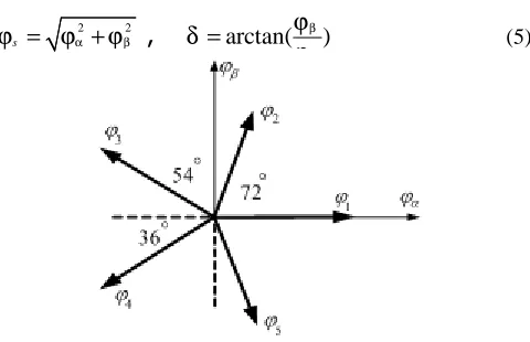
Selection of the stator flux optimal level for various speeds of the motor has been presented in [13]. In the SRM the voltages are highly non-sinusoidal, so the individual flux linkage of each phase should be firstly found by using (1). The magnitude of phase flux linkage is variable with time, but its direction is along the related phase stator pole axis. Thus there are five stationary pulsating phase flux vectors in 5-phase 10/8 SRM. To derive the unique stator flux vector, the phases flux vectors are transformed onto a stationary orthogonal two axis α β− reference frame as shown in Fig. 1. It is supposed that the phase a axis and α axis are in the same direction, so
2sin 72 3sin 36 4sin 36 5sin 72
β
ϕ =ϕ +ϕ −ϕ −ϕ
(4)
2sin 72 3sin 36 4sin 36 5sin 72
β
ϕ =ϕ +ϕ −ϕ −ϕ
The magnitude ϕsand angleδof obtained flux vector are
2 2
s α β
ϕ = ϕ +ϕ
,
arctan( β)α ϕ
δ = ϕ (5)
Fig. 1. Transformation of phases fluxes on two axis orthogonal stationary reference frame
B. Motor Torque Equation
Extraction of motor output torque equation has been illustrated in [11] that has defined the motor output torque as a function of system energy instead of co-energy as
( , )i wf
T =i ∂ϕ θ∂θ −∂∂θ (6)
It was shown in [14] that contribution of the second term in (6) is dispensable due to saturation, so
( , )i
T ≈i ∂ϕ θ∂θ (7)
On the other hand relation of the stator current and flux in the s domain can be derived as
d e
d i
sl
ϕ ω θ
−
= (8)
where ω=dθ dt. It can be seen that the stator current has a first order delay relative to∂ ∂ϕ θ , thus it can be supposed that the stator current is nearly constant during
ϕ θ
∂ ∂ variations. This means that the motor torque control can be based only on ∂ ∂ϕ θ variation. Consequently the second basic principle of DTC in SRM is:
The motor torque is controlled by positive and negative variation of ∂ ∂ϕ θ or in other words, by accelerating and decelerating of the stator flux vector.
The phases of the SRM are exited independently, thus total torque of motor is the sum of the five phases torques. As a result the individual torque of each phase T t ij( , ,j θj)
should firstly be obtained by using look-up tables. After extracting each phase torque, the motor total torque is expressed as
1
n
m i
i
T T
=
=
∑
(9)C. Power Converter Configuration
- 258 -
D. Voltage Space Vectors
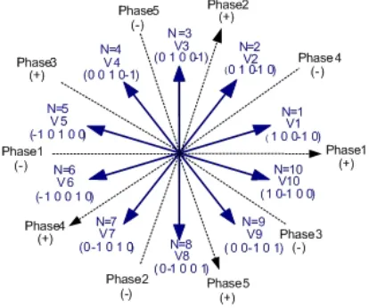
When the positive voltage of inverter dc link is applied to the phase winding, a voltage space vector can be defined in the related phase pole axis direction (e.g. vector Phase 1(+) in Fig. 2). By applying negative voltage same vector is definable but in the reverse direction (e.g. vector Phase 1(-)). Now with proper arrangement of the voltage states of all phases, the voltage space vectors vi
suitable for motor torque and flux control can be derived as shown in Fig. 2. As seen, only 10 vectors are selected from 35 possible vectors. Each vector lies in the center of decuple sectors with 2pi/10 radians width. Another vector v0
is definable when a zero voltage is applied to all five phases, in other words; v0
is achieved when each leg of the power converter is in the zero voltage state. This vector is utilized when it is not required to apply simultaneous changes in the torque and the flux.
E. Switching Table
As mentioned above, basic principles of DTC method in SRM are
1) The stator flux linkage vector of the motor is kept at constant amplitude by using (3)
2) The motor torque is controlled by positive and negative variation of ∂ ∂ϕ θ or in other words, by accelerating and decelerating of the stator flux vector.
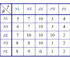
The stator flux and the motor total torque levels are controlled within two separate hysteresis bands, so when the instantaneous torque and flux cross the related band limits, they need to increase or decrease in order to remain inside the bands. To remove these requirements, the voltage space vectors and two mentioned basic principles of DTC method in SRM are utilized. Table 1 shows the switching table and required voltage space vector selection in each situation.
Fig. 2. Voltage space vectors of 5-phase 10/8 SRM
TABLE1SWITCHING TABLE
Where, Tˆ = Required variation in torque, ϕˆ= Required variation in flux, N = Stator flux sector, NL = Negative Large,
NS = Negative Small, ZE = Zero, PS = Positive Small and PL
= Positive Large. As an example when Tˆ=NL and
ˆ NS
ϕ= , it means that motor torque needs to large reduction and the stator flux needs to small reduction, so vector vN−4
will be able to respond to the system requirement. v0
is a vector that has no influence on the stator flux, and it causes the motor torque to reduce very gently. The vectors in circlets are not completely able to comply with the simultaneous requests of torque and flux, but they are the best available vectors. As an example, for N=1, Tˆ =NS and
ˆ NL
ϕ= vector v8
can not satisfy the system requirements that are small reduction in torque and large reduction in flux. Motor torque ripple minimization is one of the main aims of DTC method in SRM, so responding to torque requests by selecting of the suitable voltage space vector is prior to others. Namely a voltage space vector should be selected that causes to small reduction (NS) in the motor torque. Available vectors are v v v8, 9, 10
, but only v8
can reduce (N) the flux, and
9, 10
v v cause to flux increment (P) that is against the system request. As a result, responding to the torque request is prior to the flux request but the singe of the flux variation (N or P) should be considered. Since vectors in (10) are equal in a 10/8 SRM, for fuzzy controller simplicity in table 1 left-handed vectors are substituted with the right-handed ones.
1 9
N N
v − ≡v +
2 8
N N
v − ≡v +
3 7
N N
v − ≡v +
4 6
N N
v − ≡v + (10)
III. DESIGNING OF FUZZY CONTROLLER
- 259 - variables of the fuzzy controller, and a numerical set P as the output variable. These variables and the flux vector sector determine the suitable voltage space vectors.
As the first step of controller designing, the membership functions of the input and output variables are defined. Determination of the membership functions type depends on the designer’s experiences, and there is no predefined general rule to prefer a one type over others. In this work triangular type that is simple and easy to implement is selected. The membership functions of the input linguistic variables are shown in Fig. 3 and Fig. 4. It should be noticed that these are not the optimized membership functions. There are some optimization methods such as Kalman filter, neural networks and generic algorithm to obtain the best membership functions. Better results can be achieved by using the optimized functions.
Fig. 3. Membership functions of the motor torque
Fig. 4. Membership functions of the stator flux
Selecting an object from a number of similar objects mathematically is a discrete concept. Here the duty of the fuzzy controller is selection of the suitable voltage space vector from 10 available vectors, so the output parameter of the fuzzy logic controller should be a discrete variable. This is shown in Fig. 5 where the membership functions are defined as the numerical singleton type.
Fig. 5. Fuzzy controller output membership functions
Having the membership functions defined, the controller rule set should be designed in order to select the suitable voltage space vector. The resulting inference rules are listed in Table 2. In this table
0
if P =10 then vi =v
(11) and if P <10 then
10
if 10 then if 10 then
i P N i P N
P N v v
P N v v
+ + −
+ ≤ =
+ > =
(12)
where N =stator flux vector sector, P= fuzzy controller output and vi
= selected voltage space vector. As in the given example for table 1, when N=1, Tˆ =NL andϕˆ=NS ,
6
P = is selected that results in vN+6 from (12); this is same
as vN−4
according to (10).
TABLE2 FUZZY CONTROLLER RULE SET
Various inference mechanisms have been developed to defuzzify the fuzzy rules. In this paper the max-min inference method is applied to get an implied fuzzy set. The imprecise fuzzy control action generated by the inference engine must be transformed into a precise control action in a real application. The bisector method is used to defuzzify the implied fuzzy control variables.
IV. THE PHASES TRANSPOSITION PHENOMENON
The rotor instantaneous position calculation for each phase
( , , , , )
j j a b c d e
θ = and conversion it to the rotor
normalized position θnorm_j suitable to be applied to the
torque and flux look-up tables is not a new topic, but in order to illustrate the phases transposition phenomenon in a 5-phase 10/8 SRM it is necessary to discuss about it. The rotor normalized position for each phase θnorm_jis always a
number inside the range
_
0≤θnorm j ≤π Nr (13)
Where, Nr is the rotor poles number. Thus the nonlinear
electromagnetic torque characteristic T t ij( , ,j θj) can be
used easily. To obtain the phase instantaneous torque, separate look-up tables should be utilized for each phase, so it is needed three similar look-up table for 6/4 motor and five similar ones for 10/8 motor. The zero point of the rotor position encoder can be defined as the rotor zero axis. Assuming the rotor position is equal to zero when the rotor zero axis and the phase a axis are in the same direction, the rotor position with respect to other phases can be obtained by using Fig. 6.
Fig. 6. Extracting of rotor position
Where
0 for phase 1 for phase 2 for phase 3 for phase 4 for phase
a b
k c
d e
=
(14)
- 260 -
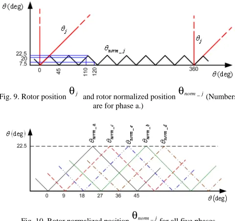
Fig. 7. Rotor position θj for all five phases
The rotor positions shown in Fig. 7 are not adequate to apply to the look-up tables, and have to be reformed properly. During rotor rotation within poles replacement with each other (e.g. 0 up to 2*pi/Nr), the positive torque is produced during first half (0 up to pi/Nr), and the negative torque is produced during second half (pi/Nr up to 2*pi/Nr). Therefore the rotor perimeter can be divided to 16 separate sections as shown in Fig. 8 where symbols + and - refer to positive and negative torque generation respectively while the rotor zero axis passes through the relative section. Thus the rotor position axis θ of the 5-phase SRM output torque characteristic is scaled within zero and 360 8 * 2=22.5
where 8 is the rotor poles number. With description above, while the rotor zero axis lies in the odd numbered sections of Fig. 8-(a), the rotor normalized position is:
(a)
(b)
Fig. 8. Rotor position sectors for
a) Phase a, b) Phase b
_ ( 1) * 22.5
norm j j Mj
θ =θ − −
(15) As an example, for phase a equivalent angle of
110
a
θ =
positioned in sector Ma =5 is20
, so angle
110
a
θ =
is replaced with angleθa =20
. When the rotor zero axis lies within the even numbered sections of Fig. 8-(a), the rotor normalized position is:
_ 22.5 [ ( 1) * 22.5 ]
norm j j Mj
θ = − θ − −
(16) As an example, equivalent angle of θa =120
positioned in sector Ma =6 is7.5
, so angle θa =120
is replaced with angle θa =7.5
(Fig. 8-(a)). Examples above are for phase a. Fig. 8-(a) changes to Fig. 8-(b) for phase b, so angle
110
a
θ =
in the above example is equal to
38
b
θ =
positioned in sectorMb =2.
Consequently, according to (16) normalized angle isθnorm b_ =7
. Similarly, rotor normalized angles can be obtained for other phases. Appling equations (15) and (16) to Fig. 7 results in Fig. 9 which shows the relation of the rotor position and the rotor normalized position of one phase. If Fig. 9 is plotted for all five phases, the rotor normalized position of all phases is derived as shown in Fig. 10.
Fig. 9. Rotor position θj and rotor normalized position θnorm_j(Numbers are for phase a.)
Fig. 10. Rotor normalized position θnorm_jfor all five phases
As shown in Fig. 7 each phase graph follows its previous phase graph. Namely phase b comes after a, c after b, d after c,
e after d and a after e, but in Fig. 10 phases sequence is different in comparison with Fig. 7. It means that the controller senses phase c instead of b, e instead of c, b instead of d and d instead of e. As a result, while applying θnorm_jand
j
i to the look-up table in order to obtain each phase instantaneous torque, phases order should be considered as following:
_
norm a
θ is applied to look-up table of phase a, θnorm_bis
applied to look-up table of phase d, θnorm_cis applied to
look-up table of phase b, θnorm_d is applied to look-up table
of phase e and θnorm_eis applied to look-up table of phase c.
- 261 - not mean that two different phases parameters are used to deriveT t ij( , ,j θj). In fact this approach is continuation of
deriving θnorm_jfrom the encoder output rotor position θ by
using Fig. 6 and equations (15) and (16).
V. SIMULATION RESULTS
To confirm the validity of the proposed method, a model of the system was constructed in Matlab/Simulink. Obtained results were compared with the results of hysteresis band control method. In both methods all parameters of the system such as sampling time (Ts= 2e-06 Sec) and solver (fixed-step discrete) are supposed to be same. In all below figures left-hand figures are for fuzzy control method.
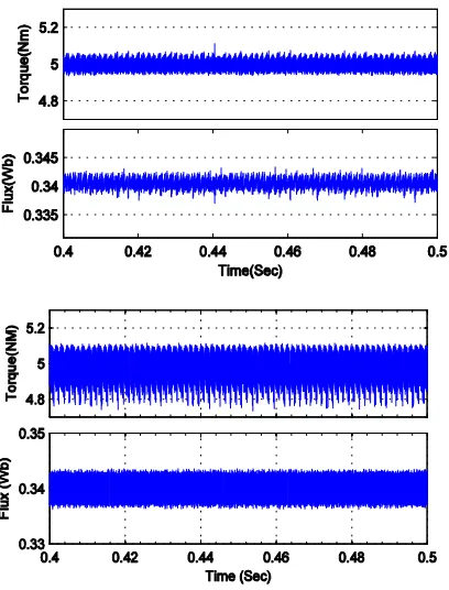
Fig. 11 shows the motor total torque under steady state condition. The motor torque and the stator flux reference levels are adjusted to 5 Nm and 0.34 Wb, and band width of torque and flux are 0.06 Nm and 0.004 Wb respectively in hysteresis band method. As seen, in both cases motor instantaneous torque and stator flux follow the reference values precisely within the certain band limits. The torque ripple in fuzzy method is 0.1 Nm that is only about 32% of the hysteresis band method with 0.31 Nm torque ripple. This is one of the most noticeable advantages of the fuzzy control method. The stator flux ripple in fuzzy method experiences a significant reduction about 50% in comparison with hysteresis band method. Since the stator flux is an electrical parameter, its ripple reduction means that the high frequency harmonics of the motor input current and hence electromagnetic inference (EMI) are reduced.
Fig. 12 shows that the fuzzy control method causes remarkable reduction in torque ripple for all levels of the motor torque. As an example, for T = 6 Nm the torque ripple is 0.13 Nm that is only 2.2% of the total torque. This amount of the torque ripple is very low for a SRM.
The performance of control methods in transient periods is evaluated by some tests. Motor torque response to the step change of the stator flux command with a constant torque level is shown in Fig. 13. In this test the stator flux is step changed from 0.34 Wb to 0.5 Wb at t = 0.35 Sec while the motor torque is adjusted to 5 Nm. It can be seen that a noticeable distortion is occurred at the change instance, but after a very short time both methods can control the motor torque.
The startup period of motor is one of the most important transient periods. Fig. 14 shows the motor startup performance for both methods. This test is performed in order to examine the low speed performance of the control system. In both methods the command torque and flux are set to 5 Nm and 0.34 Wb respectively. As shown in Fig. 14, in the output torque a large unwanted distortion occurs in transient period of t = 0 up to 3 ms. The stator flux in the startup period is shown in Fig. 14. After a short transient period, command fluxes are followed precisely in both cases.
In another test, simultaneous large changes are applied to the torque and flux commands at low speed in order to examine the system performance under difficult condition. The motor torque and flux commands experience large changes at t = 0.03 Sec when the motor speed is only 10 rad/sec. As seen in Fig. 15 the fuzzy method is able to
follow the torque and flux commands as well as the hysteresis band method. All Figs 13, 14 and 15 confirm that replacing fuzzy method instead of hysteresis band method does not affect the system transient performance.
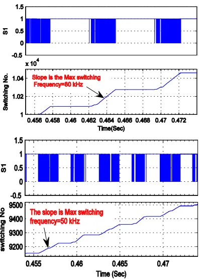
The mean and the maximum switching frequency of the switching devices are extracted from Fig. 16 and 17 for both methods respectively. Fig. 16 shows the number of switching in the time interval of 0.4 and 0.5 Sec that increases linearly, so the slope of this linear graph is proportional to the device mean switching frequency that is approximately 25.5 and 19 kHz for fuzzy and hysteresis band method respectively (the motor speed is 110 rad/sec for both methods). Closer view of this figure is shown in Fig. 17. As seen, switching is occurred only in some of time intervals. The number of switching has the nearly linear increment in these intervals. The slope of these parts is proportional to the device maximum switching frequency that is approximately 80 and 50 kHz for fuzzy and hysteresis band method respectively. These results are obtained for T = 5 Nm. If this test is repeated for different values of the motor torque accompanied by suitable flux levels, Figs 18 and 19 will be achieved. Fig. 18 shows that in the hysteresis band control method the mean switching frequency is nearly constant for different values of the motor torque, but in the fuzzy control method the mean switching frequency increases with the motor torque increment. For
4
T
<
Nm the mean switching frequency in the fuzzy control method is less than the one in the hysteresis band control method, and forT
>
4
Nm it is more than the one in the hysteresis band control method. If average mean switching frequency in Fig. 18 is calculated for both methods, 19.4 kHz as the result will be obtained. It means that switching losses in both methods are nearly equal.Similarly Fig. 19 shows that the maximum switching frequency has the same condition. Namely, in the hysteresis band control method the max switching frequency is nearly constant, but in the fuzzy control method the max switching frequency varies for different motor torque values. It means that the switching devices with higher frequency rating are needed in the fuzzy method case.
VI. CONCLUSION
- 262 -
Fig. 11. Motor torque and flux steady state response
0 0.1 0.2 0.3 0.4 0.5 0.6 0.7
1 2 3 4 5 6 7
Torque (Nm)
T
o
rq
u
e
R
ip
p
le
(
N
m
)
Hysteresis Band Fuzzy Logic
Fig. 12. Torque ripple for all levels of the motor torque
Fig. 13. Motor torque response to the stator flux step change at t = o.35 Sec
Fig. 14. Motor startup response
- 263 -
Fig. 16. The number of switching (Mean switching frequency)
Fig. 17. Closed view of the number of switching (Max switching frequency)
0 5 10 15 20 25 30 35
1 2 3 4 5 6 7
Torque (Nm)
M
e
a
n
S
w
it
c
h
in
g
F
re
q
u
e
n
c
y
(
k
H
z
) Hysteresis Band Fuzzy Logic
Fig. 18. Mean switching frequency
0 10 20 30 40 50 60 70 80 90
1 2 3 4 5 6 7
Torque (Nm)
M
a
x
S
w
it
c
h
in
g
F
re
q
u
e
n
c
y
(
k
H
z
) Hysteresis Band Fuzzy Logic
Fig. 19. Max switching frequency
REFERENCES
[1] L. Xu and E. Ruckstadter, "Direct modeling of switched reluctance machine by coupled field-circuit method," IEEE Trans. Energy Conv., vol. 10, pp. 446-454, Sept. 1995.
[2] N. J. Nagel and R. D. Lorenz, "Modeling of a saturated switched reluctance motor using an operating point analysis and the unsaturated torque equation," IEEE Trans. Ind. Applicat., vol. 36, pp. 714-722, May/June 2000.
[3] D. G. Taylor, "Adaptive control design for a class of doubly-salient motors," in Proc. 30th IEEE Conf. Dec. Cont., vol. 3, pp. 2903-2908,1991.
[4] N. J. Nagel and R. D. Lorenz, "Complex rotating vector method for smooth torque control of a saturated switched reluctance motor," in Proc. 34th Annu. Meeting IEEE Ind. Applicat. Vol. 4, pp. 2591-2598, 1999.
[5] N. Matsui, N. Akao and T. Wakino, "High –precision torque control of reluctance motor," IEEE Trans. Ind. Aplicat., vo;.27, pp. 902-907, Sep./Oct. 1991.
[6] B. Y. Ma, T. H. Liu and W. S. Feng, "Modeling and torque pulsation reduction for a switched reluctance motor drive system," in Proc. IEEE IECON. 22nd Int. Electron. Cont. Instrum.., vol.1, pp. 72-77, 1996. [7] M. Ilic'-Spong, R. Marino, S. M. Peresada and D. G. Taylor, "feedback
linearizing control of switched reluctance motors," IEEE Trans. Automat. Contr., vol. AC-32, pp. 371-379, May 1987.
[8] R. S. Wallace and D. G. Taylor, "A balanced commutator for switched reluctance motor to reduce torque ripple," IEEE Trans. Power Electron., vol. 7, pp. 617-626, July 1992.
[9] A. M. Stankovic, G. Tadmor, Z. J. Coric and I. Agirman, "On torque ripple reduction in current-fed switched reluctance motors," IEEE Trans. Ind. Electron., vol. 46, pp. 177-183, Feb. 1999.
[10] P Jinupun and P. C. K. Luk, " Direct torque control for sensorless switched reluctance motor drives," in Proc. 7th Int. Conf. Power Electron. Variable speed drives, pp. 329-334, 1993.
[11] [A. D. Cheok and Y. Fukuda, " A new torque and flux control method for switched reluctance motor drives," IEEE Trans. Power Elect., vol. 17, pp. 543-557, 2002.
[12] Chan. S and Bolton. HR, “Development of sub-kW single phase switched reluctance drives,” Conf. Rec. of ICEM, 2, pp. 527- 531, 1992.
[13] H. J. Guo, "Consideration of direct torque control for switched reluctance motors," IEEE ISIE 2006, pp. 2321-2325, july 2006. [14] J. V. Byrn and J. G. Lacy, "Characteristics of saturable stepper and