Tran Anh Son
, and Huynh Duc Thuan
HCMC University of Technology and Education, Ho Chi Minh City, Vietnam Ho Chi Minh City University of Technology, Vietnam
Corresponding Author: Pham Son Minh.
Abstract:In this paper, a baffle channel was applied to a core plate during injection molding. The temperature was observed through simulation and heating rate. The results showed that the baffle channel can support a temperature distribution better than that supported by the common channel, with a heating rate at the top point reaching up to 1.8°C/s and a core height of 50 mm. The temperature distribution also shows that the top area tends to have a higher temperature than that of the bottomowing to the thinner wall. With a higher core, the heating rate will decrease with the top area; however, with the baffle channel, the heating rate stays high.
--- --- Date of Submission: 27-09-2018 Date of acceptance: 12-01-2019 --- ---
I.
I
NTRODUCTIONNowadays, injection molding is considered to beone of the most popular methods for manufacturing plastic products. However, with the higher product quality demand of customers as well as the more complex product geometry, injection molding requires more improvements. There are many methods for improving the molding process. Among these methods, mold temperature control is an efficient method for solving the problems of the melt filling step [1–3]. In general, when the mold surface temperature increases, the quality of the part improves, although the cooling time increases, and the cycle time rises as well. Decreasing the mold surface temperature reduces the cooling time, but there is no benefit for the surface quality of the part itself [4, 5]. Therefore, a critical requirement for current studies is to increase the mold surface temperature and still maintain a cycle time that is not too long.
In injection molding, the cooling system is very important for the productivity of the injection molding process and the quality of the molded part. Much research has been conducted on the analysis of cooling systems [6, 7].Commercial computer-aided engineering software such as Moldflow [8] and Moldex3D [9] is widely applied for optimizing the cooling channel design. Many studies on the techniques of optimizing a given cooling system have also been reported [10]. Recently, methods to build better cooling systems using new forms of fabrication technology have also been reported.
In addition, with the development of product design, product geometry has become more and more complicated. Therefore, in order to cool down the part of interest, the cooling channel have to appeared at the concentrated temperature. In this paper, a cooling channel for injection molding with a U-cup shape will be researched by simulation and experiment.
II.
S
IMULATIONANDE
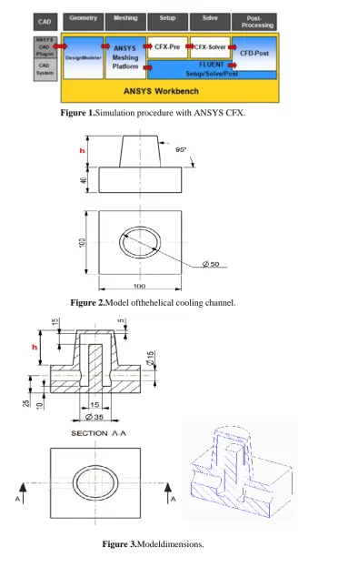
XPERIMENTFigure 1.Simulation procedure with ANSYS CFX.
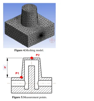
Figure 2.Model ofthehelical cooling channel.
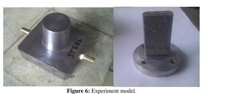
Figure 4.Meshing model.
Figure 5.Measurement points.
The meshing model is then import into the ANSYS CFX software with the mold material of C45. The
material properties are listed in Table 1.
Table 1: Material properties of C45 steel.
Mold material
Heat transfer coefficient
(W/m·K)
Specific heat(J/kg·K)
Density (kg/m3)
C45 steel 54 502,416 7,800
The governing equation used to describe the heat transfer during the cooling process is the steady-state
Laplace equation,which is expressed asfollows [11]:
𝑘𝑚
𝜕2𝑇𝑚
𝜕𝑥2 +
𝜕2𝑇𝑚
𝜕𝑦2 +
𝜕2𝑇𝑚
𝜕𝑧2 = 0. (1)
The heat transfer phenomena nearby shell plastic are governed by Poisson’s equation:
𝜌𝐶𝑝
𝜕𝑇
𝜕𝑡 = 𝑘𝑚
𝜕2𝑇𝑚
𝜕𝑥2 +
𝜕2𝑇𝑚
𝜕𝑦2 +
𝜕2𝑇𝑚
𝜕𝑧2 , (2)
where 𝑇𝑚 is the mold temperature,𝑘𝑚 is the thermal conductivity, 𝜌 is the density,𝐶𝑝 is the specify heat,𝑡 is the
Figure 6: Experiment model.
III.
R
ESULTS ANDD
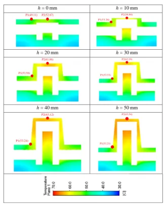
ISCUSSIONIn this research, we will study a cooling channel with a core plate height ranging from 0 to 50 mm. The initial mold temperature is 32°C. At the first step, 80°C water flows inside the channel to heat the mold. Then, 32°C water is used to cool it down. For all cycles, the temperature at points P1 and P2 will be collected. In addition, the temperature distribution is observed by simulation.
Figure 7 shows the temperature distribution of the core plate. This result proves that the baffle channel can provide good heating for the top of the core plate. In detail, when the height of the core plate increases from 0 to 50 mm, the temperature at point PT varies from 52.87 to 63.54°C. Compared with the common channel, this result shows a bright heating ability for the core plate. This is due to the fact that the hot water can reach the top area of the core plate. This advancement is clearer with a higher core plate. On the other hand, the top point of the core plate tends to have a higher temperature than that at the bottom point. This is because of the thinner wall at the top area. With the thinner wall and the same heating source from the hot water, the thermal energy easily increases the wall temperature.
In order to compare the heating rates between the case of the baffle cooling channel and thatof the common cooling channel, the heating rates at points PT and PB were calculated and compared, as shown in Fig. 8. This result shows that, with a lower core plate, the heating rate is almost the same with the value varied from 0.8 to 1.1°C/s. However, when the core height increases, the heating rate of the common channel clearly drops,whereas with the baffle channel, the heating rate tends to increase. At the top area, the heating rate can reach 1.8°C/s.
P1(53.56)
P2(61.86)
P1(53.53)
P2(62.19)
h = 40 mm h = 50 mm
P1(53.24)
P2(63.12)
P1(53.21)
P2(63.54)
T e m p er at u re ( ºC ) Time (s) (Experiment) (Experiment) (Simulation) (Simulation)
Figure 9: Temperature comparisonbetween simulation and experiment.
IV.
C
ONCLUSIONIn this paper, we tested a baffle cooling system with a cross section of 15 mm for a core plate through experiment and simulation. The temperature distribution and the heating rate were collected and compared between the baffle channel and the common channel. In general, conclusions could be drawn as follows:
With the baffle channel, the heating ability is much better than with the common channel. The heating rate at the top of the core plate could reach 1.8°C/s with a height of 50 mm.
With the temperature distribution, the baffle channel can support a higher temperature at the top of the core plate because of the thinner wall at this area.
R
EFERENCES[1]. Y. C. Lam, L. Y. Zhai, K. Tai, and S. C. Fok, “An evolutionary approach for cooling system optimization in plastic injection moulding,” Int J Prod Res, 2004, Vol. 42(10), pp. 2047–61.
[2]. X. Xu, E. Sachs, andS. Allen, “The design of conformal cooling channels in injection molding tooling,” Polymer Eng Sci, 2001, Vol. 41(7), pp. 1265–79.
[3]. Y. F. Sun, K. S. Lee, and A. Y. C. Nee, “The application of U-shape milled grooves for cooling of injection moulds,” Proc IMechE, Part B: J EngManuf, 2002, Vol. 216, pp. 1561–73.
[4]. Y. F. Sun, K. S. Lee, and A. Y. C Nee, “Design and FEM analysis of the milled groove insert method for cooling of plastic injection moulds,” Int J Adv Manuf Technol, 2004, Vol. 24(9–10), pp.715–26.
[5]. S. M. Ani, A. Muchtar, N. Muhamad, andJ. A. Ghani, “Fabrication of zirconia-toughened alumina parts by powder injection molding process: Optimized processing parameters,” Journal of Ceramics International, Vol. 40, 2014, pp. 273–80.
[6]. X. P. Li, G. Q. Zhao, and C. Yang, “Effect of mold temperature on motion behavior of short glass fibers in injection molding process,” International Journal of Advanted Manufacturing Technology, Vol. 73, 2014, pp. 639–45.
[7]. A. Agazzi, V. Sobotka, R. LeGoff, and Y. Jarny, “Optimal cooling design in injection mouldingprocesse- A new approach based on morphological surfaces,” Applied Thermal Engineering, Vol. 52, 2013, pp. 170–78.
[8]. http://www.moldflow.com/. [9]. http://w3.moldex3d.com/ .
[10]. L. Q. Tang, K. Pochiraj, C. Chassapis, and S. Manoochehri, “A computer-aided optimization approach for the design of injection mold cooling systems,” Trans ASME J Mech Design, 1998, Vol. 120, pp. 165–74.