42 Abstract— Asian cities face a serious air pollution problem from two and three-wheeled vehicles that run on two-stroke engines [3]. Inexpensive two-wheelers form a staggering 75-80% of the traffic in most Asian cities. Because two-stroke engines burn an oil gasoline mixture, they emit more smoke, carbon monoxide, hydrocarbons, and particulate matter than the gas run four-stroke engines found in newer motorcycles. Making matters worse, many Asian two-wheelers are converted into three-wheeled "baby taxis" by adding a sidecar. However the vehicle is not designed for the extra weight and the engine burns even dirtier. For small two stroke engine application, it is important that the newer concepts/systems should not adversely affect their existing advantages, particularly those of simplicity and low production and maintenance cost. The present work aims at reducing short circuiting of fresh charge by admitting cooled exhaust gas to pass through reed valves fitted at the upper end of the transfer passage in a crank case scavenged two stroke engine. This resulted in appreciable decrease in specific fuel consumption and in HC/CO emissions. The major work involved in the present work was to design and fabricate aluminium flanges which accommodate the reed valves. And an arrangement has been made at the upper end of the transfer passage in the engine cylinder to fasten the flange. A heat exchanger was fabricated in order to cool the exhaust gas at a temperature of about 400oC to avoid the pre-ignition inside the engine cylinder. The performance of the engine was tested using eddy current dynamometer.
Index Terms—EGR (Exhaust gas recirculation), Aluminium Flange, Reed Valves, Heat Exchanger.
I. INTRODUCTION
Two stroke spark ignition engines are used mainly in two wheeler vehicles which are meeting the present day individual transportation needs satisfactorily. Since there is no distinct exhaust stroke in these engines, the responsibility of driving out the combustion product from cylinder rests with the fresh charge entering into the cylinder.
Two stroke S.I engines in spite of their advantages like high specific output, ease of maintenance, they suffer from serious drawbacks like high HC/CO emissions and low brake thermal efficiency [2]. It is found that the fuel consumption and HC emissions of two stroke S.I engines are more than that of equivalent four stroke S.I engines.
In the crank case scavenged two stroke engines considerable amount of fresh fuel air mixture gets short circuited through the exhaust port during the scavenging process. Also a lot of exhaust gas gets retained inside the cylinder and dilute the fresh charge. The loss of fresh charge through the exhaust port varies from 25 to 40 % of which comes in to the cylinder depending upon the operating conditions and method of scavenging.
These factors are responsible for the high specific fuel
consumption and high HC/CO emissions. It is evident that any attempt to flush out the exhaust gas properly without losing a considerable amount of fresh charge will result in an improved performance of the two stroke SI engine.
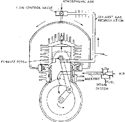
In the new design two reed valves are fitted at the upper end of the transfer ducts connecting the crank case and cylinder as shown in Fig 1.
The two reed valves permit exhaust gas to enter the transfer ducts during the upward movement of the piston due to the partial vacuums created in the transfer ducts and the crank case. This result in a complete or at least a partial filling of the transfer ducts by exhaust gas, A/F mixture is inducted in to the crank case in the conventional way. During the downward stroke of the piston the pressure inside the crank case increases and the transfer ports open and the exhaust gas which is trapped in the transfer ducts enters the cylinder and participates in the scavenging. Thereby it reduces the loss of the fresh air fuel mixture.
It is clearly proved that fresh charge loss during scavenging is the main cause for excess fuel consumption and high HC emission. Hence attempts have been made to overcome these drawbacks. Primarily on the consideration that the scavenging process should be carried out by air/cooled exhaust gases instead of A/F mixture.
Two reed valves were mounted on the top of the transfer port in a specially designed aluminium flanges. To these flanges, the cooled exhaust gas line is fitted. When the piston moves upwards vacuum is created in the crankcase and it leads to the opening of reed valves.
This result in complete or partial filling up of transfer port by air/cooled exhaust gases which scavenges the burnt products and avoids the loss of fresh A/F mixture during scavenging. Hence it results in improvement of specific fuel consumption and reduction of HC emissions.
II. SCAVENGING PROCESS
The performance of two-stroke engine depends on the art of scavenging and on port design [1]. In this case the exhaust port is opened near the end of the expansion stroke. With piston - controlled exhaust and inlet port arrangement the lower part of the piston stroke is always wasted. Thereby the useful power output which is about 15% to 40% of the expansion stroke becomes ineffective. The actual percentage varies with different designs. This early opening of the exhaust ports during the last part of the expansion stroke is necessary to permit blow down of the exhaust gases and also to reduce the cylinder pressure so that when the inlet port opens at the end of blow down process, fresh charge can enter into the cylinder. This will scavenge the burnt products. Some of the fresh charge is also lost due to short circuiting.
Modification of Two Stroke I.C Engine to
Reduce Emission and Fuel Consumption
43 Scavenging is the process of driving away the products of combustion in the cylinder from the previous cycle and replacing it with fresh A/F mixture to be burned in the next cycle.
III. MODIFIED ENGINE
In modified engine air fuel mixture and exhaust gas are supplied in the methods given below:
Primarily A/F mixture is sent through the carburettor in the conventional way. When the piston moves from BDC to TDC the pressure inside the crankcase is below atmospheric pressure. This causes the air to flow from the atmosphere to the crankcase by the above mentioned ways. When the exhaust gas flows through the reed valves the air fuel mixture present in the transfer duct as a result of the previous cycle is forced into the crankcase and exhaust gas takes its place. The sequence of events is shown in Fig 1. The flow of air through the carburettor per cycle for the same throttle positions gets reduced after the modifications. This is because the supplied exhaust gas will push the residual gas in the cylinder thereby fresh A/F. shot circuiting is reduced. During the downward stroke of the piston, pressure is built up in the crankcase and the transfer ducts as soon as the inlet port closes and hence the reed valve closes. When the piston descends further the transfer ports open and the exhaust gas in the transfer ducts enters into the cylinder instead of the air fuel mixture as in the conventional engine. This exhaust gas pushes the burned gases out, so that scavenging is done by exhaust gas. The A/F mixture which follows the exhaust gas is retained inside the cylinder to a large extent. Hence short circuiting of fresh A/F mixture can be reduced considerably.
Fig 1 Engine with improved scavenging technique
IV. EXPERIMENTAL DETAILS
The reed valves are enclosed in specially fabricated an aluminium alloy container. Gaskets are used on either side of the reed valve to prevent any leakage. Care should be taken to keep the volume of that portion of the container between the engine and the reed valve to a minimum
because this volume gets added to the crankcase volume of the unmodified engine and may affect the scavenging pressure developed to a large extent. The exploded view of the reed valve assembly is shown in Fig 2. The reed valve assembly are then screwed to the top of the transfer ducts after the fins around that area are removed by milling and a hole is drilled and tapped suitably. The connections are made in such a way that the air through the reed valve perpendicular to the cylinder axis as shown in Fig 3. Another Fig 3 shows the way how reed valve assemblies are fixed. Care should be taken to ensure that the reed valve connection does not extend over the inside surface of transfer duct wall which will obstruct the flow.
Fig 2 Reed block design
V. EXPERIMENTAL SETUP
An Eddy Current absorption dynamometer produces braking torque using the principle of eddy currents induced in a rotating metallic disk, immersed in a magnetic field [4]. It is basically an eddy current brake mounted in trunnion bearings. Its advantages are maintenance, control, simple construction and desirable speed-torque characteristics. The speed-torque characteristics make the eddy current dynamometer ideal for engine testing, and its versatility also allows effective use in testing transmissions, turbines, electric motors, gears, pumps and many other machines. The experimental setup is shown in Fig 3.
44 VI. HEAT EXCHANGER FOR EXHAUST GAS COOLING
When large quantities of heat are to be transferred, the heat transfer area of the exchanger also becomes large. In a single pass heat exchanger this requirement can be met either by increasing the length of the tube or by decreasing the diameter and increasing the number of tubes. Neither of these methods is practical because there is limitation of size and even the length of the tube cannot be increased arbitrarily as large pressure drop would occur with smaller diameter tubes. These difficulties lead to the concept of multi pass arrangements. The fluid flowing inside the tube is called the tube fluid and the fluid flowing outside the tube is called the shell fluid flow condition for a shell and tube type exchanger which is neither parallel nor counter flow type [5]. The design of heat exchanger is shown in Fig 4.
Mass flow rate of the fuel in kg/sec is given by
m
f
P SFC
(
)
(1.1)Mass flow rate of air in kg/sec is given by
a f
A
m
m
F
(1.2)Where,
A
F
=Air fuel ratioMass flow rate of exhaust gas in kg/ sec is given by
m
g
m
f
m
a (1.3)15% of Exhaust Gas is re-circulated back into the engine for scavenging process.
Heat lost by exhaust is given by
m C
g pg
T
g1
T
g2
(1.4) Heat gained by cooling water is given by
m C
w pw
T
w2
T
w1
(1.5) From equation 1.4 and 1.5 it can be inferred that heat lost by the exhaust gas is equal to the heat gained by the cooling water.m Cg pg
Tg1Tg2
mw Cpw
Tw2Tw1
(1.6)
w2 1
T =
+
m
wm C
C
g pg g1 g2
w pw
T
T
T
(1.7)LMTD (Log Mean Temperature Difference)
The log mean temperature difference is found out using the equation given below.
0
0
Q
Q
LMTD
Q
log
Q
i i
Where, 1 2Q
i
T
g
T
w (1.8)
Q
0
T
g2
T
w1 (1.9) Heat TransferThe heat transfer from the exhaust gas to the cooling water is found out using the equation given below
g pg g
Q
m C
T
(1.10)Heat Transfer Coefficient
Heat transfer coefficient for exhaust gas is given by
i
Nu
D
g
k
h
(1.11)The nusselt number for calculating the heat transfer coefficient of exhaust gas and cooling water is given below
Nu
0.296 (Re)
0.8(Pr)
0.33 (1.12)
Re
v D
i
(1.13)
v
m
gA
(1.14)
Heat transfer coefficient for cooling water is given by
h
w = uo
N
D
k
(1.15)
Re
v D
o
(1.16)Overall Heat Transfer Coefficient
The overall heat transfer coefficient is calculated using the equation given below
1
1
1
log
ee e
g i i w
D
D
D
U
h
D
k
D
h
(1.17)The amount of heat transfer can also be found out using the equation given below
Q
AU
LMTD
(1.18) From equation 1.19 the area of heat exchanger can be calculated.
Q
A
U LMTD
(1.19)
A
n D L
i (1.20)Length of Heat Exchanger
From equation 1.21the length of the heat exchanger can be calculated i
A
L
n D
(1.21)45
Fig 4 Heat exchanger design
VII. NOMENCLATURE
SFC Specific fuel consumption in kg/bhp.hr P Power in kw
pg
C
Specific heat capacity of gas in
kcal / g
k C
1
T
g Inlet temperature of the exhaust gas in C
2
T
gOutlet temperature of the exhaust gas in
C
1
T
w Inlet temperature of the cooling water inC
2
T
w Outlet temperature of the water in C
g
T
Temperature difference between exhaust gases in
C
Nu
Nusselt numberRe
Renolds NumberPr
Prandtl Numberi
D
Inside pipe diameter of heat exchanger in meters.v
Velocity in m/seck
Thermal conductivity of fluid inkcal mhr C
/
Density of exhaust gas kg/m
3o
D
Outside diameter of heat exchanger in meters.A
Area of heat exchanger inm
2n
Number of tubes inside the heat exchangerL
The length of the heat exchanger in meters.w
m
Mass flow rate of the cooling water in kg/ sec
pw
C
Specific heat capacity of the cooling water in
kcal / g
k C
VIII. RESULTS AND DISCUSSION
Effect Of Modified Engine On SFC
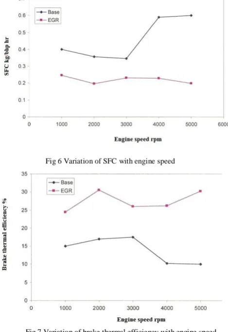
Specific fuel consumption is reduced in all speeds ranging from 20 to 30% than the conventional engine without any modification .The advantage of low specific fuel consumption means increase in mileage at road conditions. The variation of SFC with engine speed is shown in Fig 6 and Fig 12.
At full throttle and 5000 rpm engine speed and at 2.43 hp, the SFC without modification is 0.364 kg/bhp.hr and with EGR it is found to be 0.343 kg/bhp-hr. At half throttle and 5000 rpm engine speed, the SFC without modification is 0.6009kg/bhp.hr and with EGR it is found to be 0.229 kg/bhp.hr.
Effect of Modified Engine on Brake Thermal Efficiency
Brake thermal efficiency is increased at all engine speed than the conventional engine because the short circulating of fresh air fuel mixture is avoided then the unburned fuel is burned inside cylinder during scavenging process. But generally the modified engine is having higher brake thermal efficiency. The variation of brake thermal efficiency with engine speed is shown in Fig 7 and Fig 11.
At full throttle and 5000 rpm engine speed and at 2.43 hp, the brake thermal efficiency without modification is 16.51% and with EGR it is found to be 17.56%. At half throttle and 5000 rpm engine speed and at 1.35 hp the brake thermal efficiency without modification is 10.02% and with EGR engine it is found to be 26.19%.
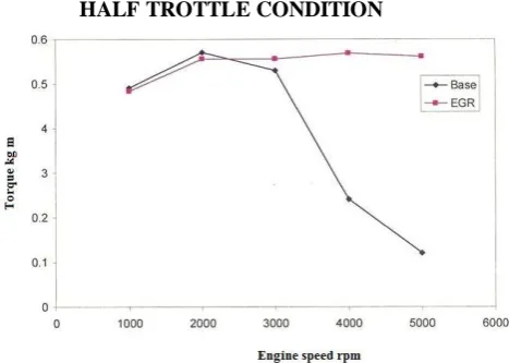
Effect Of The Engine With EGR On Torque:
There is no considerable change in torque than the conventional engine. The variation of torque with engine speed is shown in Fig 5 and Fig 10.
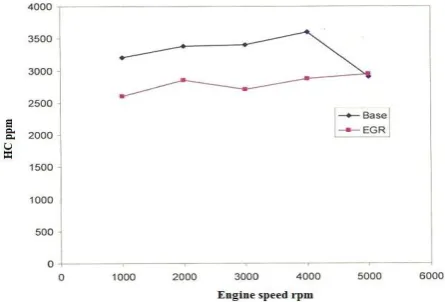
Effect Of The Engine With EGR On Emission:
There was a reduction of 25% of HC and 35% of CO in the modified engine, the reason is
1. Burning of re-circulated unburned fuel particles inside the cylinder by improved scavenging technique.
2. The short circulating fresh air fuel mixture is avoided by improved scavenging technique. The variation of HC and CO with engine speed is shown in Fig 8, Fig 9, Fig 13 and Fig 14.
At full throttle and 5000 rpm engine speed and at 2.43 hp, the HC emission without modification is found to be 2900 ppm and with EGR it is 2700 ppm. At full throttle and 5000 rpm engine speed and at 2.43 hp, the CO emission without modification is 2.8% and with EGR it is found to be 2.5%. At half throttle and 5000 rpm engine speed and at 1.35 hp, the HC emission without modification is found to be 2500 ppm and with EGR it is found to be 1730 ppm. At half throttle and 5000 rpm engine speed and at 1.35 hp, the CO emission without modification is 2.8% and with EGR it is 2.3%.
HALF TROTTLE CONDITION
46
Fig 6 Variation of SFC with engine speed
Fig 7 Variation of brake thermal efficiency with engine speed
Fig 8 Variation of CO emissions with engine speed
Fig 9 Variation of HC with engine speed
FULL THROTTLE CONDITION
Fig 10 Engine speed Vs Torque
Fig 11 Variation of brake thermal efficiency with engine speed
Fig 12 Variation of SFC with engine speed
47
Fig 14 Variation of HC with engine speed
IX. CONCLUSION
1) In the modified engine the SFC value is lower than the conventional engine in all throttle conditions. 2) The power output is slightly increased than the
conventional engine in all engine speeds because of (i) prevention of the short circulation of fresh A/F mixture and (ii) re-burning of unburned hydrocarbons by means of the improved scavenging technique.
3) On the emission side, the HC and CO emissions are drastically reduced than the conventional engine at all the speeds. It can be observed from the analysis that there is about 25 % reduction of HC emission and 30-40 % of CO emission.
4) The thermal efficiency for the modified engine is higher than the normal engine at all engine speeds
.
REFERENCE
[1] Blair G.P., Kenny R.G. -“Further development in scavenging analysis for two stroke cycle engine.” SAE Transaction -190-8000038. [2] Van Basshuysen, Richard, and Schäfer, Fred (2004)- "Internal
Combustion Engine Handbook," SAE International.
[3] Potera, Carol (2004) - “Asia’s two stroke engine dilemma.” Environ and Health perspect dilemma journal 112(11).A613.
[4] Martyr, A; Plint M (2007)-“Engine Testing - Theory and Practice.”(Third Edition ed.). Oxford, UK: Butterworth-Heinemann. [5] Sadik Kakaç and Hongtan Liu (2002) -“Heat Exchangers: Selection,