IJIRT 144456
INTERNATIONAL JOURNAL OF INNOVATIVE RESEARCH IN TECHNOLOGY235
Feedforward Linearization Technique to Reduce
Intermodulation Distortion and Spourius Free Dynamic
Range(SFDR) Measurements
Swapnil P. Kulkarni, Prof. M. R. Madki
Student of Master of Engineering Electronics Dept. W.I.T. Solapur
Professor Electronics Dept. W.I.T. Solapur
Abstract- The design of flexible, cheap, and reconfigurable
front-ends is a challenging task in terms of the RF transceiver electronics. Many requirements to the analogue components can be met by today’s technologies, however, this may not always be practical except for measurements and prototyping. This paper addresses RF impairments in wideband cognitive radios, especially non-linear distortions in the receiver. Receiver non-linearities affect the reliability of spectrum sensing, a key issue in spectrum awareness. Here, the focus is on mitigation of non-linear distortions using “Feedforward Technique”. We present experimental work studying the effects of non-linear distortions and analysing the performance of a typical wideband software defined receiver. A feed-forward mitigation algorithm with an adaptive filter has been implemented and applied to real measurement data for cleaning the baseband spectrum of distortion products. The results obtained show that a significant suppression of distortion products can be achieved.
I. INTRODUCTION
Nonlinearity in RF and IF circuits lead to two undesirable outcomes:
a. Harmonics
b. Intermodulation Distortion.
Harmonics in and of themselves are not particularly troublesome. For example, if we are listening to a QSO on
7.230 MHz, the second harmonic, 14.460 MHz is well outside the RF passband. However, when the harmonics mix with each other and other signals in the circuit, undesirable and troublesome intermodulation products can occur. Intermodulation distortion (IMD) is a common problem in a variety of areas of electronics. In RF communications in particular it represents a difficult challenge to designers who face tougher requirements on component and sub system linearity. This trend is driven in part, by an increase in radio spectrum congestion.
II. INTERMODULATION DISTORTION The harmonics produced by intermodulation distortion typically are nota problem in radio system design. There is a problem, however, that is much worse than harmonic distortion.This problem is called two-tone intermodulation distortion. Say the input to an amplifier consists of twosignals at dissimilarfrequencies:
vin =a cosω1t +a cosω2t
Here we will assume that both frequencies ω1 and ω2 are within the bandwidth of the amplifier, but are not equal to each other (ω1 = ω2 ) .
This of course is a much more realisticcase, as typically there will be multiplesignals at the input to an amplifier. For example, the two signals considered here could represent two FM radio stations, operating at frequencies within the FM band (i.e., 88.1 MHz ≤f1 ≤ 108.1 MHz and
88.1 MHz ≤f2 ≤ 108.1 MHz ).
An amplifier output is accurately described as:
𝑉𝑜𝑢𝑡= 𝐴𝑉𝑖𝑛+ 𝐵𝑉𝑖𝑛2 + 𝐶𝑉𝑖𝑛3 + ⋯
Consider first the second-orderterm if twosignals are at the input to the amplifier:
𝑉𝑜𝑢𝑡= 𝐵𝑉𝑖𝑛2
𝑉𝑜𝑢𝑡= 𝐵[𝑎. 𝑐𝑜𝑠𝜔1𝑡 + 𝑎. 𝑐𝑜𝑠𝜔2𝑡]2
𝑉𝑜𝑢𝑡= 𝐵[𝑎2𝑐𝑜𝑠2𝜔1𝑡 + 2𝑎2𝑐𝑜𝑠𝜔1𝑡. 𝑐𝑜𝑠𝜔2𝑡 + 𝑎2𝑐𝑜𝑠2𝜔
2𝑡]
Note the first and third terms of the above expression are precisely the same as the terms we examined on the previous handout. They result in harmonic signals at frequencies 2ω1 and 2ω2, respectively.
The middle term, however, is something new. Note it involves the product of cosω1t and cosω2t . Again using our knowledge of trigonometry, we find:
2𝑎2. 𝑐𝑜𝑠𝜔
1𝑡. 𝑐𝑜𝑠𝜔2𝑡
= 𝑎2cos(𝜔
2− 𝜔1) 𝑡 + 𝑎2cos(𝜔2 + 𝜔1)𝑡
IJIRT 144456
INTERNATIONAL JOURNAL OF INNOVATIVE RESEARCH IN TECHNOLOGY236
2𝑎2. 𝑐𝑜𝑠𝜔
1𝑡. 𝑐𝑜𝑠𝜔2𝑡
= 𝑎2cos(𝜔
1− 𝜔2) 𝑡 + 𝑎2cos(𝜔1 + 𝜔2)𝑡
Either way, the result is obvious —we produce two new signals. These new second-order signals oscillate at frequencies (ω1 + ω2) and |ω1 − ω2|.
Thus, if we looked at the frequency spectrum(i.e., signal power as a function of frequency) of an amplifier output when two sinusoids are at the input, we would see something like this:
Note that the new terms have a frequency that is either much higherthan both ω1 and ω2 (i.e., (ω1 + ω2)), or much lowerthan both ω1 and ω2 (i.e., |ω1 − ω2|). Either way, these new signals will typically be outside the
amplifier bandwidth.
This observation is indeed correct for second-order, two tone intermodulation products. But, we have yet to examine the third-order terms i.e.,
𝑉𝑜𝑢𝑡= 𝐶𝑉𝑖𝑛3
𝑉𝑜𝑢𝑡= 𝐶[𝑎. 𝑐𝑜𝑠𝜔1𝑡 + 𝑎. 𝑐𝑜𝑠𝜔2]3
If we multiply this all out, and again apply our trig knowledge, we find that a bunch of new third-order signals are created.
Among these signals, of course, are the second harmonics
(cos3ω1t) and (cos3ω2t) . Additionally, however, we get these newsignals:
[cos(2ω2 − ω1 )t] and [cos(2ω1 − ω2 )t] Note since cos(−x ) = cosx ,
we can equivalentlywrite these terms as: (cos(ω1 −2ω2 )t) and (cos(ω2 −2ω1 )t)
Either way, it is apparent that the third-order products include signals at frequencies |ω1 −2ω2| and |ω2 −2ω1|. Now lets look at the output spectrum with these new third order products included:
Now we should see the problem. These third-order products are very close in frequency to ω1 and ω2 . They will likely lie within the bandwidth of the amplifier.
For example, if f1 =100 MHz and f2 =101 MHz, then 2f2 -f1 =102 MHz and 2f1 -f2 = 99 MHz. All frequencies are wellwithin the FM radio bandwidth. Thus, these third-order, two-tone intermodulation products are the most significantdistortion terms. This is why we are most concerned with the third-order intercept pointof an amplifier.
III. MITIGATION TECHNIQUE
a. Feed-Forward Approach
Following the work in [1], we have implemented a feedforward approach to handle intermodulation distortions of third order (IM3), by modelling the distortions caused by interferers and subtracting them from the received signal. The mitigation algorithm requires a signal model for the imperfections, which in our case is an approximate polynomial model with adjustable coefficients. It is working at waveform level and can be inserted in front of the system-specific baseband processing.
A block scheme of the mitigation algorithm and sketches of baseband spectra at different locations along the processing chain are shown in Figure 1.
Fig.1 Block scheme of the implemented mitigation algorithm.
IJIRT 144456
INTERNATIONAL JOURNAL OF INNOVATIVE RESEARCH IN TECHNOLOGY237
to extract the crucial interferers contained in the baseband and to reproduce the distortions they cause. It is likely that only strong signals create significant IMx distortions at about 40 dB below their input signal power, thus only strong interferers near to desired signals or bands for secondary transmissions are identified in the first step. Therefore, a threshold of 20 dB below the maximum input signal level (mid of 40 dB level difference) has been used to detect strong interferers. Next, a bandpass/bandstop pair splits the distorted signal _y into a reference signal yref, containing the interferer without its distortion products, and the desired signal ydes, containing the distortions but not the interferer (inverse filter characteristics). If the frequency of the interferer changes in real applications, the filtering can be achieved by choice of the respective spectral components from the PSD, computed by a fast Fourier transform (FFT). The reference signal in the lower branch is then fed into a reference non-linearity, to regenerate the IMx products of the interferer. Here, 2nd, 3rd, and 5th order non-linearity are processed individually. At this stage, the amplitudes of the distortions are not equal to those contained in ydes due to the inaccuracy of the model. Therefore, the reference distortions are further processed by the LMS filter to adjust them to exact values. The finite impulse response (FIR) filter uses the reference signals to provide an estimate of IMx distortions contained in ydes. Thus, by subtracting the adaptive filter output from ydes, the effect of non-linearly induced interference is diminished. The error signal
𝑒(𝑡) = 𝑦𝑑𝑒𝑠(𝑡) − 𝑦3𝐿𝑀𝑆
for adapting the FIR filter weights becomes the main output of the mitigation processing. Finally, the interferer yref is added back to e, resulting in a corrected baseband spectrum with suppressed IMx distortions. Both I and Q components of the complex baseband signal have to be processed separately. Here, I/Q imbalance effects (branch mismatches) can also be included. To handle multiple interferers simultaneously, a parallel structure of feed forward processing is required. In this case, distortions stemming from a further interferer are subtracted from ydes in Equation (5). This will only be possible if the interferers and their distortion products do not coincide.
b. Experiment
The data acquisition and the processing were implemented in MATLAB. Two tone Third order signals are generated and masked into Equivalent Baseband Multitone Signal block. General Amplifire is used as a nonlinear DUT (Device Under Test). Which provide intermodulation distortion (i.e. nonlinear) signals to the LMS Decision Feedback Equaliser which is a main
block of our experiment. The nonlinear signals are one of the input for LMS Decision Feedback Equaliser the output of multitone will act as a desired input for Equaliser. Spectrum analysers at respective places gives exact waveforms and measurements such as Spurious Free Dynamic Range(SFDR) at that location. The port labeled Equalized outputs the result of the equalization process. Results are obtained by observing the waveforms before and after the LMS Desition Feedback Equaliser and also in terms of SFDR.Fig.2 shows the waveforms obtained
a)Output waveform of DUT before LMS Decision Feedback Equaliser.
b)Output waveform of LMS Decision Feedback Equaliser.
Fig.2 Waveforms of experimental result to reduce nonlinearity.
From the results it is obvious that the the nonlinearity in the Fig.a is get reduced in Fig.b.This result obtained from waveforms is also get verified by SFDR values.
c. Spurious Free Dynamic Range
IJIRT 144456
INTERNATIONAL JOURNAL OF INNOVATIVE RESEARCH IN TECHNOLOGY238
or with respect to the actual signal amplitude (dBc). The definition of SFDR is shown graphically in Fig. 3.
Fig.3 Spurious Free Dynamic Range (SFDR)
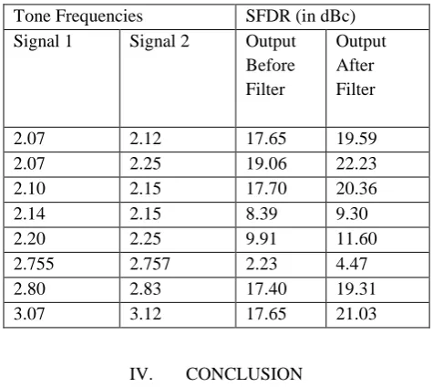
Table below shows the experimental values observed of SFDR.From definition it is clear that SFDR values should be as small as possible.
Tone Frequencies SFDR (in dBc) Signal 1 Signal 2 Output
Before Filter
Output After Filter 2.07 2.12 17.65 19.59 2.07 2.25 19.06 22.23 2.10 2.15 17.70 20.36 2.14 2.15 8.39 9.30 2.20 2.25 9.91 11.60 2.755 2.757 2.23 4.47 2.80 2.83 17.40 19.31 3.07 3.12 17.65 21.03
IV. CONCLUSION
In this paper, we presented real measurements of the nonlinear behaviour of a typical low-cost commercial SDR frontend and successfully applied the feed-forward mitigation algorithm to the measured data. The results show that a significant mitigation of non-linearly induced interference at the receiver can be achieved. Thereby, the baseband spectrum could be adjusted for reliable spectrum sensing in CR.
REFERENCES
[1] M. Allen, J. Marttila, and M. Valkama, “Digitally-enhanced wideband analog-digital interfaces for future cognitive radio devices,” in NEWCAS Conference (NEWCAS), 2010 8th IEEE International, June 2010, pp. 361–364.
[2] M. Valkama, A. Springer, and G. Hueber, “Digital signal processing for reducing the effects of RF
imperfections in radio devices - an overview,” Circuits and Systems (ISCAS), Proceedings of 2010 IEEE International Symposium on, pp. 813–816, June 2010. [3] G. Fettweis, M. Lohning, D. Petrovic, M. Windisch, P. Zillmann, and W. Rave, “Dirty RF: a new paradigm,” Personal, Indoor and Mobile Radio Communications, 2005. PIMRC 2005. IEEE 16th International Symposium on, vol. 4, pp. 2347–2355, Sept. 2005. [4] M. Valkama, A. Shahed Hagh Ghadam, L. Anttila, and M. Renfors, “Advanced digital signal processing techniques for compensation of nonlinear distortion in wideband multicarrier radio receivers,” Microwave Theory and Techniques, IEEE Transactions on, vol. 54, no. 6, pp. 2356–2366, June 2006.
[5] Q. Zou, M. Mikhemar, and A. Sayed, “Digital compensation of crossmodulation distortion in software-defined radios,” Selected Topics in Signal Processing, IEEE Journal of, vol. 3, pp. 348–361, June 2009. [6] E. Keehr and A. Hajimiri, “Digitally-assisted linearization of wideband direct conversion receivers,” European Microwave Integrated Circuit Conference, EuMIC, pp. 159–162, Oct. 2008.
[7] Y. Chiu, “Equalization techniques for nonlinear analog circuits,” Communications Magazine, IEEE, vol. 49, no. 4, pp. 132–139, April 2011.
[8] M. Oude Alink, E. Klumperink, M. Soer, A. Kokkeler, and B. Nauta, “A 50MHz-to-1.5GHz cross-correlation CMOS spectrum analyzer for cognitive radio with 89dB SFDR in 1MHz RBW,” in New Frontiers in Dynamic Spectrum, 2010 IEEE Symposium on, April 2010, pp. 1–6.
[9] M. Grimm, R. K. Sharma, M. Hein, and R. Thoma, “Mitigation of non-linearly induced interference in cognitive wideband receivers,” 7th Workshop on
Software Radios, Karlsruhe, Germany, March 2012. [10] P. B. Kenington, High-linearity RF amplifier design. Boston, Mass.[u.a.]: Artech House, 2000. [11] M. Grimm, A. Krah, N. Murtaza, R. K. Sharma, M. Landmann, R. Thoma, A. Heuberger, and M. Hein, “Performance evaluation of directional spectrum sensing using an over-the-air testbed,” 4th International Conference on Cognitive Radio and Advanced Spectrum Management, CogART’11, Barcelona, Spain, Oct. 2011. [12] D. Mahrof, E. Klumperink, J. Haartsen, and B. Nauta, “On the effect of spectral location of interferers on linearity requirements for wideband cognitive radio receivers,” in New Frontiers in Dynamic Spectrum, 2010 IEEE Symposium on, April 2010, pp. 1–9.
IJIRT 144456
INTERNATIONAL JOURNAL OF INNOVATIVE RESEARCH IN TECHNOLOGY239
[14] T. Schenk, RF imperfections in high-rate wireless systems : impact and digital compensation. Dordrecht: Springer, 2008.