FPGA based DWT-IDWT implementation of OFDM on
UWB Systems
Naagesh S. Bhat
Student
M.S. Ramaiah School of Advanced Studies
ABSTRACT
Orthogonal Frequency Division Multiplexing/Modulation (OFDM) is widely used for symbol level modulation-demodulation in communication systems for a high data rate low distance range applications. OFDM refers to both multiplexing and modulation technique to transmit parallel data using orthogonal carriers in the same or different frequency bands. In this work, DWT-OFDM is modeled which aims to send the signal in 3.168-4.752 GHz of the UWB spectrum with three working channels, while maintaining minimum bandwidth of 528 MHz. The architectures for FFT-OFDM and DWT-OFDM are modeled in Simulink software reference model and compared the performances of both from BER plots proving DWT-OFDM better over FFT-OFDM by 6dB gain. DWT-OFDM is implemented for all wavelets which proved Haar better over other wavelets by approximately 2dB. The input signal is sent as 64 samples per frame generated using two sine waves of different frequencies at 5 MHz and 10 MHz respectively. The maximum operating frequency for the design is 140 MHz with zero timing violating paths. Xpower Analyzer reports the total estimated power consumption by the FPGA board as 885 mW.
Keywords
Orthogonal frequency Division Modulation (OFDM), Ultra Wide band (UWB), Discrete Wavelet Transformation (DWT).
1.
INTRODUCTION
An efficient modulation technique is required today to achieve higher to lower rate data transfer over a range of lower to higher distances and low power respectively. The answer right now comes as Multiband-OFDM. It implements proficient orthogonal sub carrier generation blocks like FFT/IFFT or DWT/IDWT blocks to achieve spectral efficiency. On February 14th, 2002 the UWB spectrum had been officially allocated in the RF spectrum from 3.1 GHz to 10.6 GHz by the FCC. The total bandwidth of 7.5 GHz is defined from the constraints provided by FCC as the minimum bandwidth must occupy more than 20% of the centre frequency and that it must exceed 500 MHz. In 2003, a task group, IEEE 802.15.3a was developed to standardize UWB which came up with two main proposals of Multiband-OFDM (MB-OFDM) and Direct Sequence (DS) technique. The two techniques are totally different methods which transfers data in the bandwidth allocated and satisfy the power spectral densities defined by FCC. DS technique which uses short impulse signals to fill the total bandwidth.
The main disadvantage of these systems is the challenge of building RF and analog circuits with large bandwidths, high speed analog to digital converters (ADCs) to process this
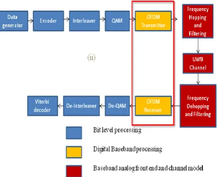
extremely wideband signal, and the significant digital complexity required to capture the multi-path energy in dense multipath environments. UWB is generally preferred for short range high data rate applications of up to 500 Mbps below 10 meters range, while 802.11a at around 5 MHz band gives just 50 Mbps in the same range which proves UWB better over 802.11a. Other earlier modulation techniques in UWB systems included impulse, pulsed multiband and then came the MBOA (Multiband OFDM Alliance). The System Architecture of UWB is shown in Figure 1.
Figure 1 UWB System Architecture
2.
OFDM
Figure 2 OFDM using Guard Bands at receiver
Figure 3 FFT based OFDM
2.1
Working Principle
There are two approaches to implement MIMO, namely single carrier and multi carrier (OFDM) systems. In single carrier approach, the whole channel is utilized to send a single packet of data at a time in a sequential manner for typically short period of time. In OFDM, the data packets are sent parallel, each using a narrowband channel ensuring each data packet travelling for longer time. Though interference still exists, since each of the data packets are made to travel for longer time, receiver can still retain the data from multi path. It proves the relation of more the multi path interference, more is the signal strength achieved at the receiver in OFDM.
Figure 4 Single and Multi carrier OFDM
In Figure 4, it can be seen that single carrier technique uses single frequency and OFDM uses multiple frequencies in parallel to send the data and in the single carrier it can be observed that little interference can degrade the whole
channel. These result in OFDM giving parallel symbols, narrow frequency and long symbol time and single carrier giving serial symbols, wide frequency and short symbol times. Equalizers are used at thereceivers in single carrier approach to reduce the ISI caused by the frequency selective channels, i.e. the attenuation. Although equalizers make the channel flat amplifying the attenuation region, it also amplifies noise which is not desired as it increases the probability of error in signal transmission. In OFDM, use of equalizers is over come where the attenuation region is rather uncovered or less data is sent in that region and also since the band is divided into narrow sub bands, the channel response is almost flat in each of them thus avoiding equalizers. In each of the sub bands the power and the data rate varies depending on the response of the channel.
3.
DESIGN OF DWT-OFDM
Orthogonal Frequency Division Multiplexing/Modulation (OFDM) is widely used for symbol level modulation-demodulation in communication systems for a high data rate low distance range applications and low data rate longer distance applications as well. The design re-presents OFDM transmitter-receiver using both IFFT-FFT and IDWT-DWT modulation implementations, proving DWT modulation better over FFT in retrieving the input signal efficiently at the receiver in the presence of the AWGN channel. Low signal power at the transmitter is achieved using IDWT-DWT, which improves the BER of the signal due to the reduction in the size of the data word over FFT-OFDM. It proves haar wavelet based DWT-OFDM is better over the IFFT-FFT implementation.
3.1
Modeling of DWT-OFDM
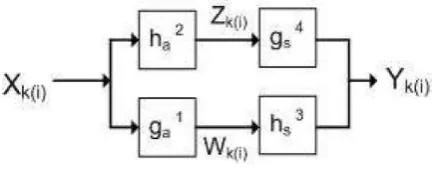
DWT-IDWT forms the vital part of the OFDM symbol modulation. IDWT is to be modeled at the transmitter and DWT at the receiver. Both the forward and reverse transforms mainly comprise of low pass and high pass fir filters having approximate coefficients and detailed coefficients. These coefficient values differ with forward and reverse transforms. These coefficients are modeled which satisfies the perfect reconstruction property shown in Figure 5.
Figure 5 DWT-IDWT Co-efficients
values are de transposed and added/ subtracted before converting to parallel data and further to demodulation.
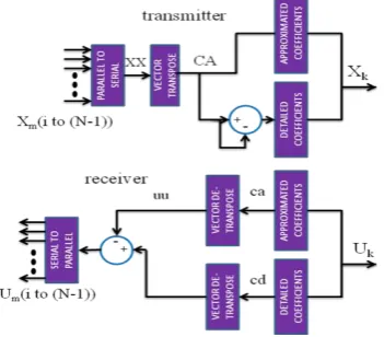
Figure 6 Symbol Structure of OFDM
3.2
Modeling of DWT-OFDM
The modeled OFDM transmitter-receiver using DWT-IDWT is designed in Simulink. The input is a quantized positive amplitude shifted sine wave of frequencies 1MHz and 5MHz. It sends signals of amplitudes in suitable range for 64-QAM from 0-63 for signal modulation, which gives out symbols on which OFDM symbol level modulation is performed. The output from 64-QAM modulation is considered giving to one of either the low pass or high pass filter of 1D one level IDWT used in the transmitter section. While the second input is given as zero padding to the other filter. The output of IDWT, which is usually double the input signal length, is transmitted through the AWGN channel. In order to improve the power spectral efficiency, the input data is transposed before that it is given to the IDWT block. At the receiver the data is given to DWT where the data is split convoluting with both the low pass and high pass filter coefficients and is down sampled. This data is de-transposed and added/subtracted according to the logic implementation at the transmitter. The data is then demodulated using a rectangular 64-de-QAM and converted from parallel to serial data to give it to the output port. The IDWT and DWT blocks act as 1D- one level in the model. Figure 6 shows the functionality of a two dimensional IDWT-DWT blocks used in the Simulink model.
3.3
Design of FFT-OFDM
In FFT-OFDM, the output from QAM modulation is given to 64 point IFFT logic. It is used to generate orthogonal sub-carriers and map the data onto the subsub-carriers. This parallel data is converted to serial and the cyclic prefix (CP) which is considered as the last 25% of the input data is added and transmitted through the AWGN channel. At the receiver, the CP is de-punctured and given to FFT modulation and amplified. This is given to QAM demodulation and is converted to serial to give it to the output port.
3.4
Performance of DWT and FFT
The two implementations of DWT and FFT based OFDM are concatenated in the same simulink model. Quantized positive amplitude shifted sine wave sending 64 samples in a frame given to 64-QAM for signal modulation, which gives out symbols on which OFDM symbol level modulation is performed. The output from QAM is given to both the DWT
and FFT based implementations. DWT-OFDM transmits a data size of 64X2, while FFT-OFDM transmitting 80X1 data length increases the signal power leading to more BER over DWT-OFDM. When calculating for BER in presence of channel for a range of SNR, it varies with respect to the input signal power that is given in the channel parameters. It is the RMS square of the signal measured before that it is given to the channel. The noise that will be added to the data when it is passed through the channel will be proportional to the input signal power with respect to the SNR. This signal power is reduced in case of DWT over FFT-OFDM as the data-word length in FFT-OFDM increases when adding cyclic prefix while transmitting which increases the transmission power. Although same input is sent to both DWT-OFDM and FFT-OFDM, both the models do not utilize the same signal power during transmission. It actually varies by the time the data is to be transmitted, which is rectified by measuring it before the channel. [9], [10] stated achieving the performances with a minimum delay of one sample and maximum delay of one frame at the receiver according to the perfect reconstruction property, which is overcome in this design. The performance plots of DWT-OFDM using Haar and FFT-OFDM in SNR range of 0-20 dB, Haar giving 0.93 at 0dB SNR and 0.04 at 20dB SNR which proves DWT better over FFT based OFDM.
4.
FPGA Implementation
Floating point implementation on FPGA leads to utilization of greater memory resources and degrades the performance/speed of the design. To overcome this drawback fixed point implementation is used which consumes fixed number of resources, as well improves the performance of the design.
4.1
Data Flow for modeling in Xilinx
System Generator
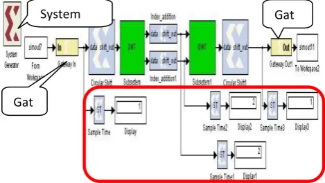
Figure 7 Design Flow using sysgen
Perfect reconstruction property for DWT-IDWT is modeled in
sysgen for implementation on FPGA. The design flow for this model is shown in Figure 7. The input signal is circular shifted before sending it to the analysis filter bank and down sampled. ‘wkeep’ block represent extracting the central part of the data by adding the data at indexes. This data is up sampled and conceded by the synthesis filter bank. The convolved data from low pass and high pass filter of synthesis bank are added extracting the central part for resizing and later circular shifted to give at the output.
4.2
Modeling of Perfect Reconstruction
Property
Figure 8 shows the Xilinx System Generator model of the perfect reconstruction property of DWT-IDWT used for the implementation of OFDM transmitter and receiver. According to perfect reconstruction property, the incoming samples are circular shifted and given to DWT. In DWT, block the circular shifted data undergoes convolution with analysis filter bank (low pass and high pass FIR filters) coefficients and are down sampled along with required operation on indexes for resizing appropriately to send it to IDWT. In IDWT, the data is first up sampled and then it undergoes convolution with synthesis filter bank (low pass and high pass FIR filters) coefficients. The coefficients of synthesis and analysis filter banks differ. The sum of the convoluted signals from synthesis filter bank is further circular shifted and given at the output. This model forms a multi rate system because of the up sampling and down sampling taking place. System generator uses clock enable to switch between the different sample rates.
Figure 8 Xilinx System generator Model for DWT-IDWT
4.3
Simulation using Sysgen Model
Black box implementation is included the Sysgen model implementation, which imports custom verilog HDL to the model and connects to the other sysgen blocks. While running the model, it acts as a black box while connecting its inputs and outputs. Such blocks are implemented for circular shift and wkeep which takes the central part of the data by adding data at indexes.
4.4
Simulation using Sysgen Model
Synthesized verilog HDL netlist and testbench is generated from the Sysgen model using the system generator token for implementation on Virtex-5. The logic is implemented among the Configurable Logic Blocks (CLBs) and BRAMs routed among the IO blocks via switching matrices on the FPGA. Each CLB comprise of slices (number vary with respect to device). Every Slice contains four 6 input Look Up Tables (LUTs) which represent the combinational logic using multiplexers; arithmetic logic for carry out, 4 flip flops for storing the signal values on Virtex-5. The design occupies 202 out of 17,280 slices, 112 six input LUT- FF pairs out of 656 on FPGA. STA report shows the minimum time period of 7.160ns achievable for a given 10ns, i.e., the maximum operating frequency at 140 MHz while analyzing all the paths with zero errors being detected. Xpower Analyzer report shows the total estimated power consumption by the FPGA board as 885 mW.
5.
Simulation
The library generation of the model for hardware-software co-simulation, implementation results on Virtex-5 and the simulation results of software reference model of the re-configurable DFe MIMO-OFDM module are discussed. It also consists of the simulation and synthesis results of the re-configurable DFe MIMO-OFDM module design in ModelSim, Xilinx ISE and Xilinx System Generator.
5.1
Hardware Software Co-Simulation
The hardware library for the DWT-IDWT Sysgen model targeting Virtex-5 is generated, which is required for the hardware-software co-simulation environment. A single block is generated that represent the hardware of the model, could replace all the Sysgen blocks as shown in Figure 9, is linked to a bit stream that will be downloaded on to the FPGA during co-simulation. During the process of generating the library, it undergoes synthesis, translate, map, place and route, bit file generation that is required to implement on FPGA. This block includes all the functionality and comprise of one input through which input from Simulink is fed and the output from which the output data could be analyzed using Simulink sinks.
Figure 9 hardware Software Co-Simulator
Figure 10 shows the hardware-software co-simulation environment which incorporates both the sysgen custom (software) model and the hardware library generated (harware) in the same model checking with the results from both the paths. The outputs from both software and the data read back from FPGA are found to be same as the input with a delay of three samples. This verifies the software and hardware outputs to be the same.
Figure 10 Hardware Software Cp-Simulator Environment
System Generator Token
Gat ew ay In
5.2
Device Utilization Summary
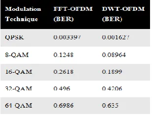
Table 1 shows the comparison of BER performances when using QPSK and M-ary QAM in FFT and DWT based OFDM systems. Although QPSK represents more resistance towards noise, it yields low data rates and works best for a constant transmitter, while QAM yields high data rates and works for a linear transmitter. Both of the modulations could be employed by OFDM using a switching module appropriately using for different applications.
Table 1 Comparison of BER Performance
5.3
Performance results
Simulations of software reference model with respect to input and output of DWT-OFDM and its performance plots of BER with respect to a range of SNR are presented in Section 4.4. Functional Simulations of the sub blocks during the FPGA implementation is presented in the Section 5. Hardware-Software Co-simulation verification results are presented in Section 5.1. To summarize all the results presented in the thesis are given below
1. Software reference model (Simulink) Functional Simulations
2. Simulink BER performance plots comparing FFT-OFDM and DWT-OFDM
3. Simulink BER performance plots comparing all the wavelets using DWT-OFDM
4. RTL (hardware) Functional Simulations of the sub-blocks
5. Resource Utilization Summary, timing and power analysis reports post place and route implementation on FPGA
6. Hardware-Software Co-simulation verification
5.4
Limitations of the implementation
Implementation of DWT-OFDM proved efficient over FFT-OFDM only in case of Haar wavelet. Higher order QAM consumes more transmission power leading to higher BER, which achieves higher data rates though. Although, the delay is overcome in the software reference model (Simulink), the hardware implementation of the perfect reconstruction property results in delay of 3 samples at the output. Not all the blocks in system generator like FIR Filter are compatible for a given FPGA board.
6.
CONCLUSION
DWT-OFDM outperformed FFT-OFDM by approximately 6dB gain in BER. Haar wavelet showed best performance over Biorthogonal (bior3.3, bior5.5), Daubechies (db2,db4), reverse biorthogonal (rbior3.3, rbior5.5) by approximately 2dB. Though QPSK yielded better BER through observations,
it is used for a constant power output transmitter, while QAM works better for a linear transmitter. HDL generated from ‘sysgen’ resulted a synthesizable, timing constrained netlist for the design precisely achieving the output. The benefits using Sysgen regarding the number of slices occupied is better over the resource utilization by custom HDL. The maximum operating frequency achieved for the design is 140 MHz when implemented on Virtex-5 FPGA board. Hardware-Software co-simulation environment has been developed and verified the results of software and hardware to be the same.
7.
REFERENCES
[1] Ramjee Prasad, OFDM for Wireless Communications
Systems, Artech House Universal personal
communications series, ISBN 1-58053-796-0, 2004
[2] Yu-Wei Lin, Chen-Yi Lee, Design of an FFT/IFFT Processor for MIMO OFDM Systems, IEEE transactions on Circuits and Systems-I, Vol. 54, No. 4, April 2007
[3] Oscar Robles Palacios and Carlos Silva Cardenas,
Design and implementation of a reconfigurable OFDM modulator for software-defined radios, IEEE Transactions on Communications, 2008
[4] Anuj Batra, Jaiganesh Balakrishnan and Anand Dabak,
Multiband OFDM: Why it Wins for UWB, Texas Instruments, June, 2003
[5] Yuh-Ren Tsai, Xiu-Sheng Li, Kasami Code-Shift-Keying Modulation for Ultra
[6] Wideband Communication Systems, Institute of Communications Engineering, National Tsing Hua University, Taiwan
[7] K. Abdullah and Z. M. Hussain, Studies on DWT-OFDM and FFT-OFDM Systems, IEEE International Conference on Communication, Computer and Power, February 15-18, 2009
[8] W. Saad, N. El-Fishawy, S. EL-Rabaie, and M. Shokair,
An Efficient Technique for OFDM System Using Discrete Wavelet Transform, Springer-Verlag Berlin Heidelberg, pp. 533–541, 2010
[9] R. Dilmirghani and M. Ghavami, Wavelet Vs Fourier Based UWB Systems, 18th IEEE International Symposium on Personal, Indoor and Mobile Radio Communications, pp.1-5, September, 2007
[10]Khaizuran Abdullah and Zahir M. Hussain, Impulsive Noise Effects on DWT- and WPTOFDM versus FFT-OFDM, International Conference on Communication, Computer and Power (ICCCP’09), February 15-18, 2009
[11]Hiroki Harada, Marco Hernandez and Ryuji Kohno,
Multiband and Multicarrier Wavelet Packet Multiplexing for UWB Transmissions, Proceedings of the 2008 IEEE International Conference on Ultra-wideband (ICUWB2008), Vol. 3, 2008
[12]Khaizuran Abdullah, Katrina L. Neville, and Zahir M. Hussain, An Interference Cancellation Algorithm for Fourier-Based and Wavelet-based OFDM Systems, International Conference on Advanced Technologies for Communications, 2008
Multiband OFDM UWB System in the Presence of Narrowband Interference, IEEE Globecom proceedings, 2009
[14]Khaizuran Abdullah, Seyed Mehdi Lajevardi and Zahir M. Hussain, QAM Modulations over Wavelet based
OFDM Channel for Facial Expression Recognition,