Ongole, (AP), India, E-mail: [email protected]
Abstract:- Flexible AC Transmission Systems (FACTS) devices are used to control power flow in the transmission lines. This paper describes the concept of power flow control in transmission line by Distributed FACTS (D-FACTS), called Distributed Interline Power Flow Controller (DIPFC). The DIPFC is taken from the Unified Power Flow Controller (UPFC). The DIPFC can be considered as to be eliminated common dc link UPFC. Same as UPFC, DIPFC also having series and shunt converters. DIPFC having multiple small sizes single phase three series converters and single three phase shunt converter. The three single phase series converters are located to connecting the two transmission lines to moderate the voltage sag and swell as to improve the power quality problems. In DIPFC the operation of both the converters are independent. The active power substitute between the shunt and series converters, which is throughout the universal dc link in the UPFC, now the active power throughout the transmission lines at the third-harmonic frequency. Modelling and principle of operation is presented in this paper. Distributed Interline Power Flow Controller (DIPFC) is located connecting the two parallel transmission lines of infinite bus. The case studies are simulated in MATLAB/ Simulink and the results validate the DIPFC has ability to improve the power quality.
Keywords:- FACTS, Power Quality, Sag and Swell improvement, Distributed Power Flow Controller (DPFC), Distributed Interline Power Flow Controller (DIPFC)
I. INTRODUCTION
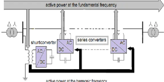
In the last decade, the electrical power quality issue has been the main concern of the power companies [1]. Power quality is defined as the index which both the delivery and consumption of electric power affect on the performance of electrical apparatus [2]. From a customer point of view, a power quality problem can be defined as any problem is manifested on voltage, current, or frequency deviation that results in power failure [3]. The power electronics progressive, in particular in flexible alternating-current transmission system (FACTS) and convention power devices, affect power quality improvement [4]. Generally, custom power devices, e.g., dynamic voltage restorer (DVR)[5], are used in medium-to-low voltage levels to improve customer power quality [6]. Most serious threats for sensitive equipment in electrical grids are voltage sags (voltage dip) and swells (over voltage). These disturbances occur due to some events, e.g., short circuit in the grid, inrush currents involved with the starting of large machines, or switching operations in the grid. The FACTS devices, such as unified power flow controller (UPFC) and synchronous static compensator (STAT-COM), are used to improve the disturbance and improve the power system quality and reliability [8]. In this paper, a distributed power flow controller, introduced in as a new FACTS device, is used to mitigate voltage and current waveform deviation and improve power quality in a matter of seconds. The DPFC structure is derived from the UPFC structure that is included one shunt converter and several small independent series converters, as shown in Fig. 1 [9].
The DPFC has same capability as UPFC to balance the line parameters, i.e., line impedance, transmission angle, and bus voltage magnitude [10]. The Interline Power Flow Controller (IPFC) is comprised of a number of SSSCs with the common link at their DC sides. The IPFC provides series compensation for multiple lines. This compensation can be both active and reactive. The reactive power required for the series compensation is generated by the series converter itself and the required active power is exchanged from other converters Similar to the DPFC, the DIPFC consists of multiple single-phase series converters, which are independent from each other. As the DIPFC is a power flow control solution for multiple transmission lines, the series converters are installed in different line.
Fig. 1. The DPFC Structure
II.
DPFC PRINCIPLE
In comparison with UPFC, the main advantage offered by DPFC is eliminating the enormous amount of DC-link and instate using 3rd harmonic current to active power exchange. In the following subsections, the DPFC basic concepts are explained.
A. Eliminate DC Link and Power Exchange
Inside the DPFC, the transmission line is used as to connection between the DC terminal of shunt converter and the AC terminal of series converters, instead of direct connection using DC-link for power exchange between converters. The strategy for power trade in DIPFC depends on power hypothesis of non-sinusoidal parts. In view of Fourier arrangement, a non-non-sinusoidal voltage or current can be existing as the entirety of sinusoidal segments at diverse frequencies. The result of voltage and current segments gives the dynamic force. As the basic of a few terms with diverse frequencies are zero, so the active power comparison is as take after:
𝑃 =
∞𝑖=1𝑉
𝑖𝐼
𝑖cos 𝜑𝑖
(1)
Where 𝑉𝑖 and 𝐼𝑖are the voltage and current at the 𝑖𝑡ℎ harmonic, respectively, and 𝜑𝑖is the angle between the
III.
DPFC CONTROL
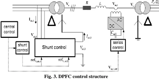
The DPFC has three control methodologies: central controller, series control, and shunt control, as appeared in Fig. 3.
A. Central Control
This controller deals with every one of the series and shunt controllers and sends reference signs to them two.
B. Series Control
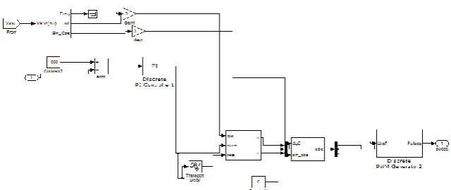
Every single-stage converter has its own particular series control through the line. The controller inputs are series capacitor voltages, line current, and series voltage reference in the 𝑑𝑞 frame. The block diagram of the series converters in Mat lab/Simulink environment is demonstrated in Fig. 4.
Fig. 3. DPFC control structure
Any series controller has a low-pass and a third pass filter to make central and third harmonics current, individually. Two single-phase lock loop (PLL) are utilized to take frequency and phase data from system [11]. The block diagram of series controller in Matlab/Simulink is shown in Fig. 5. The PWM-Generator block manages switching processes.
C. Shunt Control
Fig. 5. Block diagram of series control structure in Matlab/Simulink
Each converter has its own controller at different frequency operation (fundamental and third-harmonic frequency). The shunt control structure block diagram is shown in Fig. 6
Fig. 6. The shunt control configuration: (a) for fundamental frequency
Fig. 6.1. The shunt control configuration: (b) for third-harmonic frequency
IV.
DISTRIBUTED INTERLINE POWER FLOW CONTROLLER
Figure 7: IPFC configuration
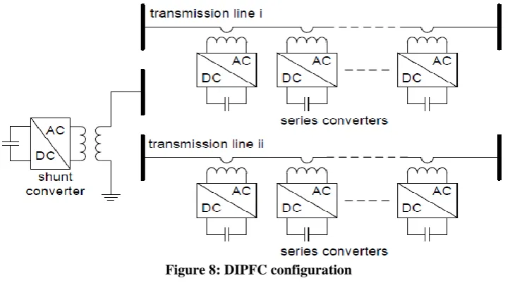
Similar to the DPFC, the DIPFC consists of multiple single-phase series converters, which are independent from each other. As the DIPFC is a power flow control solution for multiple transmission lines, the series converters are installed in different lines. The DIPFC can also include shunt converters, but these are not compulsory. The single line diagram of a DIPFC is shown in Figure 8.There is an exchange of active power between the DIPFC converters and this active power is exchanged in the same transmission line at the 3rd harmonic frequency. If the DIPFC is without a shunt converter, the series converters in one transmission line will exchange active power with the converters in the other lines. If there is a shunt converter in the DIPFC, the shunt converter will supply the active power for each series converter.
Figure 8: DIPFC configuration
V.
POWER QUALITY IMPROVEMENT
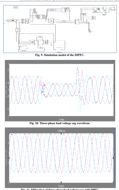
Fig. 9. Simulation model of the DIPFC.
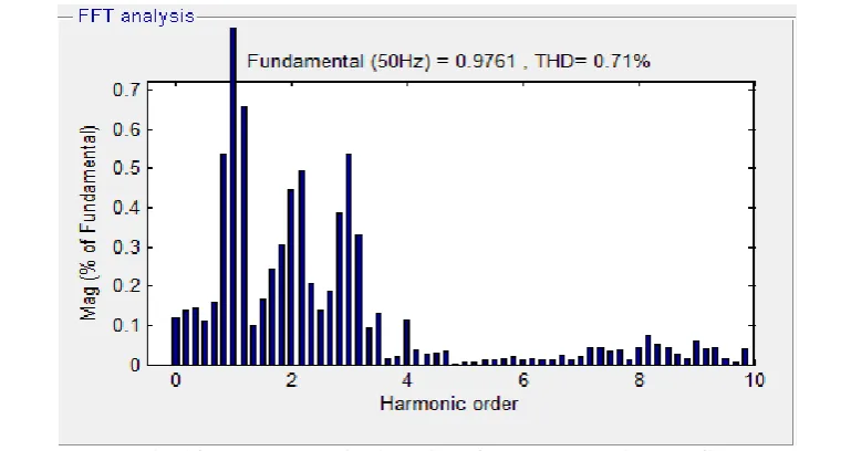
Fig. 10. Three-phase load voltage sag waveform.
Fig. 12. Three-phase load current swell waveform without DPFC
Fig. 13. Mitigation of three-phase load current swell with DPFC
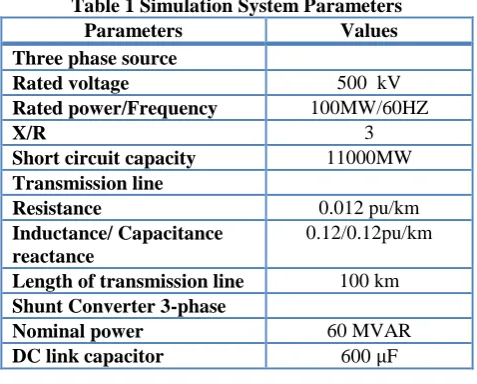
The load voltage harmonic analysis without presence of DPFC is illustrated in Fig. 13. It can be seen, after DPFC and DIPFC implementation in system, the even harmonics is eliminated, the odd harmonics are reduced within acceptable limits, and total harmonic distortion (THD) of load voltage is minimized from 45.67 to 0.71 percentage and also total harmonic distortion (THD) of load voltage is minimized 0.39 percentage (Fig. 13), i.e., the standard THD is less than 5 percent in IEEE standards.
Fig. 15. Total harmonic distortion of load voltage with DIP
VI.
CONCLUSION
In power sector the power quality improvement of the power transmission systems is an essential issue. In this revise, the appliance of DPFC and DIPFC as a novel FACTS device, in the voltage sag and swell mitigation of a system composed of a three-phase source connected to a non-linear load through the parallel transmission lines is simulated in Matlab/Simulink background. By implementing a three-phase fault close to the system load voltage dip is investigated. To identify the voltage sags and find out the three single phase reference voltages of DIPFC, the SRF scheme is used as a detection and determination method. The simulation results show the efficiency of DIPFC in power quality improvement, particularly in sag and swell mitigation when compared with DPFC.
Table 1 Simulation System Parameters
Parameters Values
Three phase source
Rated voltage 500 kV
Rated power/Frequency 100MW/60HZ
X/R 3
Short circuit capacity 11000MW
Transmission line
Resistance 0.012 pu/km
Inductance/ Capacitance reactance
0.12/0.12pu/km
Length of transmission line 100 km
Shunt Converter 3-phase
Nominal power 60 MVAR
DC link capacitor 600 μF
REFERENCES
[1]. Ahmad Jamshidi,a, S. Masoud Barakati,b, and Mohammad Moradi Ghahderijani, Power Quality Improvement and Mitigation Case Study Using Distributed Power Flow Controller, 978-1-4673-0158-9/12/$31.00 ©2012 IEEE
[2]. S. Masoud Barakati, Arash Khoshkbar Sadigh and Ehsan Mokhtarpour, “Voltage Sag and Swell Compensation with DVR Based on Asymmetrical Cascade Multicell Converter”, North American Power Symposium (NAPS), pp.1 – 7, 2011
[3]. Alexander Eigels Emanuel, John A. McNeill “Electric Power Quality”. Annu. Rev. Energy Environ 1997, pp. 263-303.
Distributed Power Flow Controller (DPFC)” IEEE Transaction on Power Electronics, vol. 25, no.10, October 2010.
[11]. Zhihui Yean, Sjoerd W.H. dc Haan and Braham Frreira “DPFC control during shunt converter failure” IEEE Transaction on Power Electronics 2009.