Rashmi et al. World Journal of Engineering Research and Technology
ADVANCED HEAD LAMP LEVELING SYSTEM BY OCCUPANT
DETECTION METHOD
R. Rashmi* and Dr. B. Ramachandra
PES College of Engineering, Mandya, Karnataka-571401, India.
Article Received on 25/08/2018 Article Revised on 15/09/2018 Article Accepted on 05/10/2018
ABSTRACT
Head lamps are designed to light / illuminate the way ahead.
Traditionally automotive designs use two beams; Main beam is
normally used on unlit roads where long sight distance is needed and
high speeds are allowed and Dipped beam is normally used to provide
good road illumination & still offer no dazzling intensity (glare) to the oncoming traffic. The
primary objective for the use of headlamp leveling systems in the vehicle is to control the
increase in glare that occurs with headlamps aimed too high. Dipped beam light cut off will
move up-down as per the vehicle loading conditions such as co- passenger, rear seat
occupants and boot load. Due to different loading conditions, naturally beam will move up
and certainly cause the glare for the oncoming traffic. To overcome this problem National
and International regulations currently specifies a limited range within which the vertical aim
(illumination range) of the dipped headlamps must be maintained under various vehicle load
conditions either by automatically or by manual headlamp leveling system to avoid the glare
for the oncoming traffic. Earlier one is cost effective and generally used in all types of lower
and middle class of vehicle. Second one used in higher segment class of vehicles and more
expensive. To overcome this problem Investigation and formulation of low cost
semiautomatic headlamp leveling devices is developed. This proposed technology will
address the lower and mid-segment vehicle in India, considering India is a still developing
and lower economy country. This paper describe the study of load sensors located in different
seating position and boot load to provide the signals to the headlamp actuator for maintaining
the required beam pattern. Finally total system was integrated and calibrated as per the
national and international norms.
World Journal of Engineering Research and Technology
WJERT
www.wjert.org
SJIF Impact Factor: 5.218*Corresponding Author R. Rashmi
KEYWORDS: Headlamp; glare, headlamp leveling, micro-controller, automotive safety.
1.0INTRODUCTION
The motor vehicle industry is one of the major pioneer activities for social and economic
progress of any country. Automotive manufacturer always depends on new technologies for
vehicular accessories like lighting systems, mirrors, seat belts, interior fittings, windscreen
bumpers dashboards etc. These components are defined as safety critical components in
Central Motor Vehicle Rule (CMVR). In India it is reported[1] during the year 2016 the
number of deaths occurred every hour were 17 due to road accidents. The occurrence of road
accidents is observed to be higher during night when visibility is at its lowest. The two
factors which affect visibility are insufficient illumination and glare caused by the oncoming
traffic. Road accident at night is disproportionately high in numbers & severity compared to
day time driving. The statistics bring out that 60% of all road accidents take place during
night, when only 15% of the total traffic is plying.[8] Fig shows the statistics of the road
accidents for oncoming (vehicles coming from opposite) and following traffic (self driving)
due to glare. This shows the importance of the vehicle lighting system for night visibility.
Fig. 1: Percent frequencies of respondents for oncoming and following glare.
1.1.Headlamp leveling system
National and International regulations[4,5] currently specifies a limited range within which the
vertical aim (illumination range) of the dipped headlamps must be maintained under various
vehicle load conditions either by automatically or by manual headlamp leveling system to
leveling systems in the vehicle is to control the increase in glare that occurs with headlamps
aimed too high. Dipped beam light cut off will move up-down as per the vehicle loading
conditions such as co- passenger, rear seat occupants and boot load. Due to different loading
conditions, naturally beam will move up and certainly cause the glare for the oncoming
traffic. The Fig. 2 demonstrate the head lamp beam movement due to different loading
conditions.
Fig. 2: Head lamp beam movement due to different loading conditions.
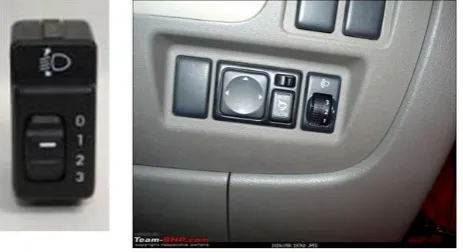
To overcome these problems, presently there are two types of leveling systems viz; manual
and automatic head lamp leveling systems. The manual headlamp leveling system is
controlled by the driver with a switch and having various positions 0-4 or 0-3 range. These
leveling systems can take care of loading effect on vehicle where the manual switch is placed
near the driver and two typical switches are shown in Fig. 3.
Fig. 3: Two types of manual switches near driver.
The automatic headlamp leveling system linked to the vehicle suspension system will keep
the headlamps position correctly as per the requirement regardless of vehicle load and
without driver intervention.
Automatic headlight leveling control system fall into two categories: Static and dynamic.
dynamic systems also correct headlamp aim during acceleration both from standing starts and
when under way and when breaking.
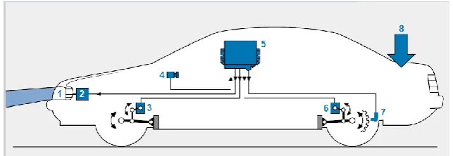
Components of a typical headlight leveling control system include in Fig 4. Sensors on the vehicle axles to precisely measure the vehicle’s inclination or tilt. An ECU that uses the
sensor signals as the basis for calculating the vehicle’s pitch angle. The ECU compares these
data with the specified values and responds to deviations by the transmitting appropriate control signals to the headlamps motor. Headlamp’s motor will adjust the lamp to the correct
angle.
1. Head lamp 2. Actuator 3.Front suspension travel sensor 4. Light switch (ON/OFF) 5. ECU
6. Front suspension travel sensor 7. Wheel speed sensor 8. Load.
Fig. 4: System components of automatic leveling devices.
In both the system, aiming is achieved by movement of headlamp reflector by actuator
present in the headlamp. The signals either from automatic leveling or manual received by
actuator depending on the loading conditions of the vehicle and actuator will rotate the
reflector of the headlamp to achieve the required beam level.
2.0 SCOPE OF THE STUDY
Second one used in higher segment class of vehicles and more expensive. Certainly
second version is not viable in Indian scenario considering the segment of vehicle
category present and cost of leaving. The manual leveling device is cost effective and
generally used in all types of lower and middle class of vehicle. Manual leveling device is
totally depends on the driver responsibility, he needs to operate dashboard control lever or
knob depending the loading conditions of his vehicle and it is always a question mark in
the system. The study shows that.
Drivers not aware of the headlamp leveling function and it’s relation with passenger
Drivers using the headlamp leveling function on Highways for better visibility by pulling
up the beam irrespective of any load.
Drivers using the headlamp leveling function in low lit areas by pulling down the beam
Maximum drivers do not change the company setting for headlamp leveling device ever
in the vehicle life span.
No awareness of existence of headlamp switch or knob by 40 % of drivers.
To overcome this situation low cost adoptive headlamp leveling devices concept is developed
based on the occupant and load detection in the vehicle. In this system, presence of occupant
and boot load is detected by load sensors located below the each passenger seat and luggage
compartment. Load sensors located in different seating position and boot load will provide
the signals to the headlamp actuator to maintain the required beam pattern. Total system is to
be integrated and calibrated as per the norms.
3.0 METHODOLOGY
The following methodology adopted for the study:
Study is limited to M1 category of vehicles with 5 seating capacity
Study is conducted on static mode without consideration of vehicle
Regular headlamp with manual motor was used for this study for the simulation
5 different types of Load cell was used for the purpose of occupant detection
Initial study was conducted with load range from 50 kg to 75 kg on each load cell.
The components (digital weighing machine, amplifier, control unit, leveling motor etc)
required for the research investigation were procured, studied and integrated in the
laboratory. The system will be placed inside the vehicle and integrated to the vehicle
headlamp and headlamp motor. Total system is to be integrated and calibrated as per the
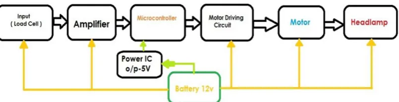
national and international norms. Block Diagram of the circuit for automatic leveling control.
The Fig 5 shows that block diagram of working principle of head lamp leveling system.
The load cells generate an electrical signal in response to the substrate being stressed by the
weight. The electrical signal changes as a function of the weight of the seat occupant. The
system was integrated with the consideration of electrical signal output v/s load of each load
cell and same is connected to the headlamp leveling motor through amplifier and micro
controller. The Figure 6 shows the working principle of the headlamp leveling system.
Fig. 6: Working principle of the headlamp leveling system.
The relay operates with the microcontroller and gives supply to motor according to the
different load. The above electronic board is fitted to the headlamp of a vehicle and
experiments were conducted.
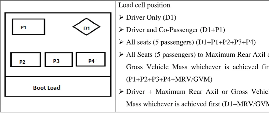
3.1 Combination of Seat Numbers and Switching Positions
For the purpose of experimentation, M1 category (5-seater) vehicle is used, hence the seat
positions are simulated same as in M1 category vehicles. With the number of seat occupants
detected, the combinations for the switch positions are set and accordingly the motors are
being controlled. Fig.7 depicts seat Position layout of M1 Category Vehicle.
Load cell position
Driver Only (D1)
Driver and Co-Passenger (D1+P1)
All seats (5 passengers) (D1+P1+P2+P3+P4)
All Seats (5 passengers) to Maximum Rear Axil or
Gross Vehicle Mass whichever is achieved first
(P1+P2+P3+P4+MRV/GVM)
Driver + Maximum Rear Axil or Gross Vehicle
Mass whichever is achieved first (D1+MRV/GVM
The M1 category, 5 seater sedan vehicle was identified to conduct the experiments. The
loading specification for the vehicle is as follows:
Unladen Rang 2244Kg
Gross Vehicle Weight (GVM) 3050Kg
Maximum Rear Axle 1775Kg
Maximum Front Axle 1500Kg
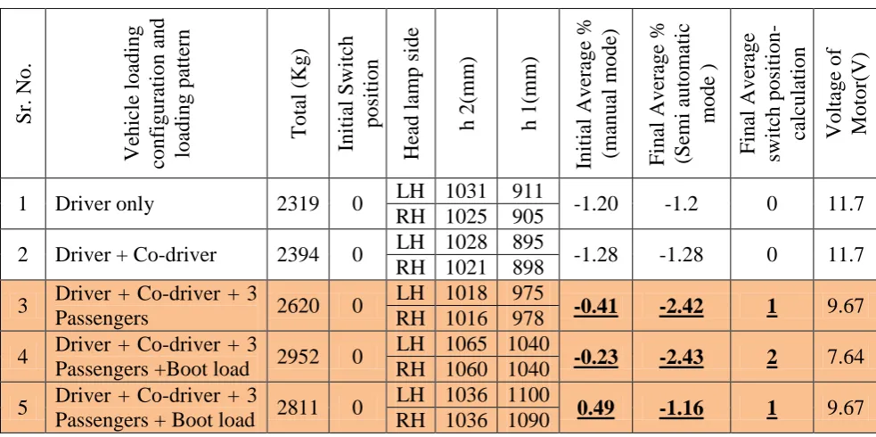
The table 1 shows experiment results of the Head lamp beam movement position with various
loading conditions and is lies between the ranges of -0.5 to -2.5% cut-off as per the standard
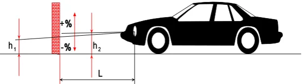
requirements.[4,5] The following figure 8 represents the head lamp filament reference position,
test distance and range of beam movement requirements. The same is follows for all beam
angle representation.
Fig. 8: Head lamp beam inclination.
Inclination is expressed in percentage inclination
Where
h1 is the height above the ground, in millimeters, of the above- mentioned characteristic
point, measured on a vertical screen perpendicular to the vehicle longitudinal median
plane, placed at a horizontal distance L.
h2 is the height above the ground, in millimeters, of the center of reference (which is
taken to be the nominal origin of the characteristic point chosen in h1).
L is the distance, in millimeters, from the screen to the centre of reference (10 M).
4.0 EXPERIMENTATION
The system tested as per the procedure defined in ECE R 48 / AIS: 008 with each loading
position. The readings were taken in the zero position, then after in each loading conditions
for both Left (LH side) and right (RH side) hand side of head lamps beam position. The
average beam inclination is calculated with the consideration of LH and RH side headlamp
automatically within the specified range as per the standards by occupant detection using load
sensors and headlamp motor activation to move the head lamp beam through reflector.
Conducted repeatability and reproducibility of the test and observed that results are
satisfactory. Also noted the beam movement and correlated with the manual leveling switch
position. The table shows the Head lamp beam movement position with various loading
conditions.
Table 1: Head lamp beam movement position with various loading conditions.
S r. No. Ve hicle loading configur ati on a nd loading pa tt ern Tota l (K g) Initial S witch posi ti on He
ad lamp si
de
h 2(mm) h 1(mm)
Initial Ave ra g e % (ma nua l mode) F inal Ave ra ge % (Semi automatic mode ) F inal Ave ra ge switch posit ion -ca lcula ti on Voltage of Mot or (V )
1 Driver only 2319 0 LH 1031 911 -1.20 -1.2 0 11.7 RH 1025 905
2 Driver + Co-driver 2394 0 LH 1028 895 -1.28 -1.28 0 11.7 RH 1021 898
3 Driver + Co-driver + 3
Passengers 2620 0
LH 1018 975
-0.41 -2.42 1 9.67
RH 1016 978
4 Driver + Co-driver + 3
Passengers +Boot load 2952 0
LH 1065 1040
-0.23 -2.43 2 7.64
RH 1060 1040
5 Driver + Co-driver + 3
Passengers + Boot load 2811 0
LH 1036 1100
0.49 -1.16 1 9.67
RH 1036 1090
5.0 CONCLUSION
The literature review indicates the possible prospects of further investigations in the field of
automotive head lighting and night safety; hence the low cost adoptive headlamp leveling
devices concept investigation is formulated using occupant detection method using load
sensors. Experiments were conducted with different loading conditions in static level
conditions. The experimental results shows that the headlamp leveling position is under limit
as specified in the standard with different loading conditions With this system, manual
leveling switch can be replaced by this system, so that malfunctioning of beam leveling is
removed and will be achieved more safety during night driving. Above concept may be one
of the solutions to overcome all these problems. However, more detail study need to be
conduct regarding the selection of load sensor, integration in the seat, calibration of load,
calibration of leveling motor with respect to different load cell electrical signals, adoption in
6.0REFERENCES
1.
http://www.newindianexpress.com/nation/17-people-killed-every-hour-in-road-accidents-in-India/2016/06/10/article3474499.eceIntro 2.
2. Drivers’ perceptions of headlight glare from oncoming and following vehicles; Report
No. DOT HS 809 669 publication by National Highway Traffic Safety Administration
(NHTSA).
3. Nighttime Glare and Driving Performance: Research Findings Report No. DOT HS 811
043 669 publication by National Highway Traffic Safety Administration (NHTSA).
4. AIS-008_Rev1Installation Requirements of Lighting and Light-Signalling Devices for
Motor Vehicle having more than Three Wheels, Trailer and Semi-Trailer excluding
Agricultural Tractor.
5. Uniform provisions concerning the approval of vehicles with regard to the installation of
lighting and light-signalling devices, Regulation No. 48 (Revision-12).
6. Michael F. Krey. Titled “Headlight leveling device” US patent No. 4733334 A– 22, Mar
1988.
7. "Predicting Weight Distribution from Occupant Load Using a Monte Carlo Method,"
SAE Technical Paper 2012-01-1925, 2012, doi:10.4271/2012-01-1925.
8. Sushil Kumar Choudhary, Rajiv Suman, Sonali and Honey Banga titled, “Electronic Head Lamp Glare Management System for Automobile Applications” International Journal of