©2013 JNAS Journal-2013-2-9/410-416 ISSN 2322-5149 ©2013 JNAS
Multi Machine PSS Design by using Meta
Heuristic Optimization Techniques
Mostafa Abdollahi
*, Saeid Ghasrdashti, Hassan Saeidinezhad and Farzad
Hosseinzadeh
Department of Electrical Engineering, Bandar Lengeh Branch, Islamic Azad University, Bandar Lengeh, Iran
Corresponding author: Mostafa Abdollahi
ABSTRACT: Designing power system stabilizer (PSS) in multi machine power systems has always been reported as a critical issue; because, unsuitable adjusting of PSSs may lead to stability decreasing instead of stability improvement. Therefore, a coordinated PSS design should be carried out in multi machine power systems. In this paper, all PSSs are simultaneously tuned in a multi machine power system. A Meta heuristic optimization technique namely artificial bee colony (ABC) algorithm is used to adjust the PSSs parameters. Non linear simulations are carried out to validate of results. Simulation results clearly verify that the proposed technique enhances the dynamic stability of the system considering uncertainties.
Keywords: Artificial Bee Colony, Dynamic Stability, Multi Machine Power System, Non Linear Simulations, Power System Stabilizer.
INTRODUCTION
411
extended PSS design method for multi-machine systems. This is based on: pseudo global system models; frequency response based model order reduction technique; and the pole assignment algorithm. The new design method is applied to a practical ten-machine power system. A power system stabilizer design method for multi-machine power systems is given by (Yang, 1997). In this design method, the design problem is translated into an equivalent problem of decentralized controller design for Multi-Input Multi-Output (MIMO) control systems. Subject to a condition based on the structured singular values, each stabilizer can be designed independently. The robust stability condition for power systems with stabilizers on can be easily stated as to achieve a sufficient interaction margin, and a sufficient gain and phase margin defined in the classical feedback theory during each independent design. Within this general framework, the conventional stabilizer design methodology based on the concept of synchronous and damping torques is used to decide the design details of each stabilizer. The suggested design method is applied to a model of a practical 10 machine power system. In paper (Wang and Swift, 1998) the phase compensation method is used to design multiple FACTS-based stabilizers and PSSs in multi-machine power systems. A three-machine power system is demonstrated and TCSC-based stabilizer and PSS are designed by phase compensation method. An observer-based controller to improve stability in power systems, by using the excitation of synchronous generators, is introduced by (Leon et al., 2012). The strategy goal is to attain maximum damping injection and to increase the transient stability, while good voltage regulation performance is maintained. The proposed strategy presents two important features from the implementation point of view. First, the controller only needs sensing currents and rotor speed, and second, previous knowledge of network parameters and topology is not required. Several comparisons in multi-machine scenarios with current power system stabilizers are presented. These studies confirm the viability and the performance improvement when conventional solutions are replaced by the proposed approach.
This paper deals with power system stabilizer design in multi machine power system considering uncertainty. A new optimization algorithm namely artificial bee colony (ABC) algorithm is used for tuning power system stabilizers. A multi machine power system is considered as case study and installed with PSSs. Simulation results demonstrate the ability and effectiveness of the proposed method in stability improvement.
Power system stabilizer
A power system stabilizer (PSS) is a device which provides additional supplementary control loops to the automatic voltage regulator (AVR) system and/or the turbine-governing system of a generating unit.A PSS is also one of the most cost-effective methods of enhancing power system stability.Adding supplementary control loops to the generator AVR is one of the most common ways of enhancing both small-signal (steady-state) stability and large-signal (transient) stability.Adding such additional control loops must be done with great care; it is known that an AVR(without supplementary control loops) can weaken the damping provided by the damper and field windings. This reduction in the damping torque is primarily due to the voltage regulation effects inducing additional currents in
the rotor circuits that oppose the currents induced by the rotor speed deviation Δω (Machowski et al., 2011).
The main idea of power system stabilization is to recognize that in the steady state, that is when the speed
deviation is zero or nearly zero, the voltage controller should be driven by the voltage error ΔV only. However, in
the transient state the generator speed is not constant, the rotor swings and ΔV undergoes oscillations caused by
the change in rotor angle. The task of the PSS is to add an additional signal which compensates for the ΔV
oscillations and provides a damping component that is in phase with Δω. This is illustrated in Figure 1; where the
signal VPSS is added to the main voltage error signal ΔV. In the steady state VPSS must be equal to zero so that it
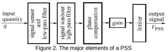
does not distort the voltage regulation process. The general structure of the PSS is shown in Figure 2; where the
PSS signal VPSS can be provided from a number of different input signals measured at the generator terminals. The
412
Figure 1. block diagram of supplementary control loop for the AVR system
Figure 2. The major elements of a PSS
Artifital bee colony algorithm
The ABC algorithm was first proposed by Karaboga (Karaboga, 2005) in 2005. Similar to other intelligent swarm algorithms, it simulates the foraging behavior of honeybees. There are three groups of honeybees in the ABC algorithm, employed bees, onlooker bees, and scout bee. Employed bees take the responsibility of searching new food sources. After the process completed, they fly back to the hive and share the position and nectar amount information with onlooker bees in the dancing area. By observe the dance of employed bees, onlooker bees decide the food sources which they want. Scout bees carry out the random search while the food source is exhausted. In the original ABC algorithm (Karaboga and Basturk, 2007), the number of food sources is equal to the number of employed bees. The number of employed bees is equal to the number of onlooker bees simultaneously. In other words, a half of the colony size is employed bees. The process of the artificial bee colony algorithm is shown as below (Liao et al., 2013):
Step 1: Initialize the population.
Step 2: Send the employed bees to the food sources.
Step 3: Memory the best food source in employed bees by fitness evaluation.
Step 4: Employed bees come back to hive and share information of food sources with onlooker bees, then onlooker bees fly to the food sources which they have chosen.
Step 5: Memory the best food source in onlooker bees by fitness evaluation. Step 6: The scout bees fly to the search area and look for new food sources.
Step 7: While the terminal condition is met or maximum cycle number is reached, Algorithm stop; otherwise, go back to step 2.
Simulated to other swarm evolution algorithms, the ABC algorithm has its own operators such as employed bee phase, onlooker bee phase and scout bee phase.
The employed bee phase
In the employed bee-phase, artificial bees update the new food sources by following expression(Liao et al., 2013):
j
k j i j i j i j
i x x x
m (1)
where mij and x
j
i represents the new and old solution (food source) in jth dimension of the ith individual,
respectively; φi
j is a random real number between {-1, 1} corresponding to xji, it controls the effectiveness of
distance between xji and x
j
k, k is an index number selected randomly in food sources. Obviously, a new food source
is affected by the status of the bee colony distribution. After the new food source updated, original ABC chose the food source by the fitness value of each corresponding employed bee. Greedy selection has been applied in the ABC algorithm in order to determine which food source is better and would be remembered after the employed bee phase.
The onlooker bee phase
413
Scout bee phase
After onlooker bee phase, a modified bee colony distribution is determined. If one of these food sources cannot be improved in predetermined cycle ‘‘limit’’, it will be replaced by a new one according to following equation(Liao et al., 2013):
j j
j j
i x rand x x
x min [0,1] max min (1)
where xjmin and xjmax represent the lower and upper boundary in dimension j, respectively; rand {0, 1} is the random
number between {0, 1}; Scout bee phase in ABC is applied to abandon the solution which cannot be improved (Liao et al., 2013).
Power suystem stabilizer design
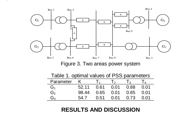
A multi machine power system comprising four synchronous generators is considered as case study. The proposed test system is depicted in Figure 3 and the system data are given in (Anderson and Farmer, 1996). Three
generators G1, G2 and G3 are equipped with PSSs and their parameters are tuned by using ABC method. The PSS
configuration is as follows; it comprises two compensators with time constants, T1–T4 with an additional gain K.
Δω ST 1
ST 1 ST 1
ST 1 ST 1
ST K output Stabilizer
4 3
2 1
W W
(2)
The optimum values of K and T1–T4 are accurately computed using ABC Algorithms. Objective function is also
considered as following which is the Integral of the Time multiplied Absolute value of the Error (ITAE). The
optimum values of the parameters are obtained and summarized in the Table 1.
n
1 i
t
0
idt
Δω t
ITAE (3)
G4
G3
G2
G1
π π
π π
π
π
π
Bus 1
Bus 2 Bus 3
Bus 4 Bus 5
Bus 6 Bus 7 Bus 8 Bus 9
Figure 3. Two areas power system
Table 1. optimal values of PSS parameters
Parameter K T1 T2 T3 T4 G1 52.11 0.61 0.01 0.88 0.01 G2 98.44 0.65 0.01 0.85 0.01 G3 54.7 0.51 0.01 0.73 0.01
RESULTS AND DISCUSSION
Simulation results
414
Figure 4. Speed G1 following disturbance
Figure 5. Speed G2 following disturbance solid: with PSS; dashed: without PSS
Figure 6. Speed G3 following disturbance solid: with PSS; dashed: without PSS
Figure 7. Speed G4 following disturbance solid: with PSS; dashed: without PSS
0 5 10 15 20 25 30 35 40 45 50
0.9998 0.9999 1 1.0001 1.0002 1.0003 1.0004
Time (s)
S
p
e
e
d
G
1
(
p
.u
.)
0 2 4 6 8 10 12 14 16 18 20
0.99 0.995 1 1.005 1.01 1.015
Time (s)
S
p
e
e
d
G
2
(
p
.u
.)
0 2 4 6 8 10 12 14 16 18 20
0.9985 0.999 0.9995 1 1.0005 1.001 1.0015 1.002
Time (s)
S
p
e
e
d
G
3
(
p
.u
.)
0 5 10 15 20 25 30 35 40 45 50 0.9999
1 1.0001 1.0002
Time (s)
S
p
e
e
d
G
4
(
p
.u
415
Figure 8. output signal of installed PSS on G1 following disturbance
Figure 9. output signal of installed PSS on G2 following disturbance
Figure 10. output signal of installed PSS on G3 following disturbance
CONCULSION
A multi machine power system stabilizer design by using BAC algorithm was presented by this paper. Three PSSs were simultaneously tuned and simulated on the given test system. The simulation results were carried out to validate the proposed technique in damping oscillations. The ability of PSSs in damping low frequency oscillations was successfully shown.
REFERENCES
Anderson PM, Farmer RG. 1996. Series compensation of power systems. PBLSH Incorporated.
Bhattacharya K, Kothari ML, Nanda J, Aldeen M, Kalam A. 1998. Tuning of power system stabilizers in multi-machine systems using ise technique. Electric Power Systems Research. 46:119-31.
Gao F, Strunz K. 2009. Multi-scale simulation of multi-machine power systems. International Journal of Electrical Power & Energy Systems. 31:538-45.
Karaboga D, Basturk B. 2007. A powerful and efficient algorithm for numerical function optimization: artificial bee colony (ABC) algorithm. Journal of global optimization. 39:459-71.
0 2 4 6 8 10 12 14 16 18 20
-0.2 -0.15 -0.1 -0.05 0 0.05 0.1 0.15 0.2
Time (s)
O
u
tp
u
t
o
f
P
S
S
o
n
G
1
0 2 4 6 8 10 12 14 16 18 20
-0.2 -0.15 -0.1 -0.05 0 0.05 0.1 0.15 0.2
Time (s)
O
u
tp
u
t
o
f
P
S
S
o
n
G
2
0 2 4 6 8 10 12 14 16 18 20
-0.2 -0.15 -0.1 -0.05 0 0.05 0.1 0.15 0.2
Time (s)
O
u
tp
u
t
o
f
P
S
S
o
n
G
416
Karaboga D. 2005. An idea based on honey bee swarm for numerical optimization. Techn Rep TR06, Erciyes Univ Press, Erciyes.
Leon AE, Mauricio JM, Solsona JA. 2012. Multi-machine power system stability improvement using an observer-based nonlinear controller. Electric Power Systems Research. 89:204-14.
Liao X, Zhou J, Ouyang S, Zhang R, Zhang Y. 2013. An adaptive chaotic artificial bee colony algorithm for short-term hydrothermal generation scheduling. International Journal of Electrical Power and Energy Systems. 53:34-42.
Machowski J, Bialek J, Bumby J. 2011. Power system dynamics: stability and control. John Wiley & Sons2011.
Wang HF, Swift FJ. 1998. Multiple stabilizer setting in multi-machine power systems by the phase compensation method. International Journal of Electrical Power & Energy Systems. 20:241-6.
Yadaiah N, Venkata Ramana N. 2007. Linearisation of multi-machine power system: Modeling and control – A survey. International Journal of Electrical Power & Energy Systems. 29:297-311.
Yang TC. 1995. Extending a stabilizer design method to multi-machine power systems. International Journal of Electrical Power & Energy Systems. 17:275-80.