ISSN: 2395-7549
A Review on Abrasive Jet Machining
Mistri Ankit N. Shah Hardil D.
UG Student UG Student
Department of Mechanical Engineering Department of Mechanical Engineering Chhotubhai Gopalbhai Institute of Technology, Bardoli Chhotubhai Gopalbhai Institute of Technology, Bardoli
Patel Urvin R. Manish Maisuria
Assistant Professor Assistant Professor
Department of Mechanical Engineering Department of Mechanical Engineering Chhotubhai Gopalbhai Institute of Technology, Bardoli Chhotubhai Gopalbhai Institute of Technology, Bardoli
Dhaval Patel Assistant Professor
Department of Mechanical Engineering Chhotubhai Gopalbhai Institute of Technology, Bardoli
Abstract
Advance machining processes are used where higher accuracy and surface finish is required. One of them, Abrasive jet machining is a non-traditional machining process in which a high-pressure air stream and abrasive particles impinge on a work surface through a nozzle. Abrasive jet machining (AJM) removes material through the action of a focused beam of abrasive jet directed at the workpiece the resulting erosion can be used for cutting, drilling and debarring etc. With the increase of needs for machining of ceramics, semiconductors, electronic devices and L.C.D., AJM has become a useful technique for micromachining. it is more useful in industries for precision work. Material removal rate during this process affected by different parameters like abrasive particle size, the velocity of abrasive flow rate, gas pressure, standoff distance etc.
Keywords: Abrasive jet machine (AJM), Material removal rate (MRR), Stand-off distance (SOD), Abrasive mass flow rate, Erosion rate
_______________________________________________________________________________________________________
I. INTRODUCTION
Abrasive jet machining (AJM) is a processing nontraditional machine which operators on no physical contact between tool and workpiece so there is no thermal stresses and shocks developed. AJM is applied for many applications like cutting, cleaning, polishing, deburring, etching, drilling and finishing operation. In Abrasive jet machining, abrasive particles are made to impinge on work material at high velocity. A jet of abrasive particles is carried by carrier gas or air. The high-velocity stream of abrasives is generated by converting pressure energy of carrier gas or air to its Kinetic energy and hence high-velocity jet. Nozzles direct abrasive jet in a controlled manner onto work material. The high-velocity abrasive particles remove the material by micro-cutting action as well as a brittle fracture of the work material.
II. ABRASIVE JET MACHINING
Background:
This novel technology was first initiated by Franz to cut laminated paper tubes in 1968 and was first introduced as a commercial system in 1983. In the 1980s garnet, abrasive was added to the water stream and the abrasive jet was born. In the early 1990s, water jet pioneer Dr. John Olsen began to explore the concept of abrasive jet cutting as a practical alternative for traditional machine shops. His end goal was to develop a system that could eliminate the noise, dust, and expertise demanded by abrasive jets at that time. In the last two decades, an extensive deal of research and development in AJM is conducted.
III. ABRASIVE JET MACHINING PROCESS
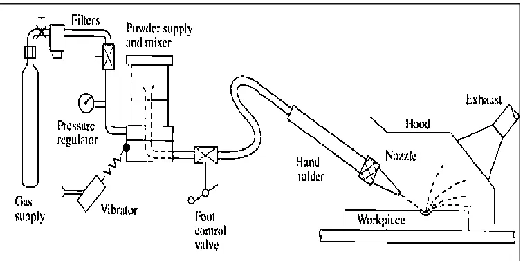
COMPONENTS [6]
Abrasive Jet Machining consist of 1) Air/gas supply cylinder/compressor 2) Filter
5) Mixing chamber 6) Foot control valve 7) Nozzle
8) Piping system 9) Guideways 10) Abrasives
Air/gas supply cylinder/compressor
Cylinder basically used for the storage of air/gas at certain high pressure & this pressurized gas/air is supplied forward to the system. Same way, Air compressors collect and store air in a pressurized tank, and use pistons and valves to achieve the appropriate pressure levels within an air storage tank that are attached to the system.
Filter
The main purpose of using a filter is to purify the air/gas passed through it by removing an unnecessary or unwanted particle from air/gas flow.
Pressure Regulator
The line pressure is regulated by a pressure regulator. A pressure regulator’s primary function is to match the flow of gas through the regulator of gas place upon the system. A pressure regulator includes a restricting element, a loading element, and a measuring element.
Vibrator
The main function of the vibrator in this is to proper mixing of two different materials by vibration mechanism. Mixing chamber
A mixing chamber is a small compartment in which proper mixing of gas/air abrasive particle takes place with help of vibrator attached to it.
Foot control valve
It is used to maintain required pressure at the tip of the nozzle for material removal from the workpiece by controlling valve. Nozzle
The abrasive particles are directed into the work surface at high velocity through nozzles. The rate of material removal and the size of machined area are influenced by the distance of the nozzle from the workpiece.
Piping system
The piping systems are required for carrying the compressed air from the compressor to the mixing chamber and from the mixing chamber to the nozzle orifice via the regulator. It is required to maintain the pressure in the line without eroding the pipe.
Guide ways(x-y table)
The x‐y table is the most important part of the AJM over which the workpiece has to be kept and machined. The main function of the guideway is to make sure that the machine tool operative element moves along the predetermined path. The guideway provides a smooth and linear motion in machine tool due to which higher accuracy and precision can be obtained. Guideway has a mechanism to bear the load and to guide their linear motion simultaneously.
Abrasives
An abrasive is a material that is used to shape or finish a workpiece through rubbing which leads to part of the workpiece being worn away. While finishing a material often means polishing it to gain a smooth surface. Various abrasives used are Silicon oxide (SiO2), Silicon carbide (SiC), Aluminum oxide (Al2O3) of different sizes for cutting and drilling operation.
(J4R/ Volume 03 / Issue 02 / 003)
First, Gas /dry air is supply from the cylinder/compressor & reaches to a filter.
After the filtration, air/gas move towards pressure regulator, which indicate the pressure of the air/gas flow.
Then this air/gas is mixed with abrasive particle powder in the mixing chamber with the help of vibrator attached to it. Then this mixer of abrasive particle & air/gas reaches to foot control valve, which uses for maintaining the required pressure
of mixer at the tip of the nozzle.
Mixer with sufficient pressure reaches to the nozzle, nozzle increases the velocity of the mixer and strike the workpiece at very high velocity, say about 300m/s.
So due to the high velocity of air-abrasive mixer strike at the work surface, material removal can take place & machining can do.
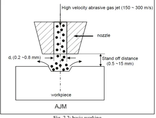
Fig. 2.2: basic working
This is a process of removal of material by impact erosion through the action of a concentrated high-velocity stream of grit abrasives entrained in high-velocity gas stream AJM is different from the shot or sand blasting, as in AJM, finer abrasive grits are used and parameters can be controlled more effectively providing better control over product quality.
In AJM, generally, the abrasive particles of around 50 microns grit size would Impinge on the work material at a velocity of 150-300 m/s from a nozzle of ID 0.5mm with a standoff distance of around 0.5mm-15mm. The kinetic energy of the abrasive particles would sufficient to provide material removal due to brittle fracture of the workpiece or even micro cutting by the abrasives.
Mechanics for AJM [4]
Abrasive particle impinges on the work surface at a high velocity and this impact causes a tiny brittle fracture and the following air or gas carries away the dislodged small workpiece particle.
So the removal of the material takes place due to micro-cutting action as well as a brittle fracture of the work material.
TYPICAL PARAMETERS FOR AJM [1]
Abrasive
Material: - Al oxide, brass, silicon carbide Shape: - irregular / spherical
Size: - 10 to 50 micron
Mass flow rate: – 2 to 20 gm/min Carrier gas
Composition - dry air, nitrogen(N2), carbon dioxide(CO2) Pressure – 2 to 10 bar
Flow rate – 5 to 30 L/min Abrasive Jet
Velocity – 100 to 300 m/s(1000 km/hr) Standoff distance – 0.5 to 15 mm Impingement angle – 60° to 90°
Mixing ratio – Volume flow rate of abrasives/Volume flow rate of gas Nozzle
Material – tungsten carbide(WC)/ Sapphire Diameter – (internal)0.2 to 0.8 mm
Life – 300 hours for sapphire, 20 to 30 hours for WC
ADVANTAGES & DISADVANTAGES FOR AJM [1]
Advantages:-
– Capital cost is low and it is easy to operate and maintain AJM.
– The process is free from chatter and vibration as there is no contact between the tool and workpiece.
– The Higher surface finish can be obtained.
– Ability to cut fragile, brittle hard & heat sensitive material without damage.
– Thin sections of hard brittle materials like germanium, mica, silicon, glass, and ceramics can be machined It provides cool cutting action, so it can machine delicate and heat sensitive Material.
– It has the capability to cut intricate shape holes of any hardness and brittleness material. Dis-advantages:-
Limited capacity due to low MRR. MRR for glass is 40 gm/minute.
Abrasive powders cannot be reused as the sharp edges are worn and smaller Particles can clog the nozzle. Short standoff distances when used for cutting, damages the nozzle.
A dust collection system is a basic requirement to prevent atmospheric pollution and health hazards. Nozzle life is limited (300 hours).
Abrasive jet machining cannot applicable for a ductile material. Stray cutting is difficult to avoid.
APPLICATION OF AJM [1].
This is used for abrading and frosting glass more economically as compared to Etching or grinding.
Cleaning of metallic smears on ceramics, oxides on metals, resistive coating etc.
AJM is useful in the manufacture of electronic devices, drilling of glass wafers, deburring of plastics, making of nylon and Teflon parts permanent marking on rubber stencils, cutting titanium foils.
Used for cutting thin fragile components like germanium, silicon etc.
Used for drilling, cutting, deburring etching and polishing of hard and brittle materials.
Most suitable for machining brittle and heat sensitive materials like glass, quartz, sapphire, mica, ceramics germanium, silicon, and gallium.
EFFECTIVE PROCESS PARAMETERS [1][2][3]
The followings are some of the important parameters of abrasive jet machining which directly or indirectly affect the material removal rate (MRR) during the process.
(J4R/ Volume 03 / Issue 02 / 003)
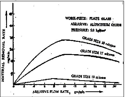
Effect of Abrasive mass flow rate and grain size on MRR:-
Fig. 2.3: variation in MRR with change in abrasive flow rate for different grain size
Above graph shows the variation in MRR with a change in abrasive flow rate for different grain size say 10, 27 & 50 microns. It is clear from the figure that at a particular pressure MRR increase with the increase of abrasive flow rate and is influenced by the size of abrasive particles. But after reaching optimum value, MRR decreases with further increase of abrasive flow rate. This is owing to the fact that Mass flow rate of gas decreases with the increase of abrasive flow rate and hence mixing ratio increases causing a decrease in material removal rate because of decreasing energy available for erosion.
Effect of exit gas velocity and abrasive particle density
This graph shows variation in exit gas velocity with respect to abrasive particle density. The velocity of carrier gas conveying the abrasive particles changes considerably with the change of abrasive particle density as indicated in the figure.
The exit velocity of gas can be increased to critical velocity when the internal gas pressure is near twice the pressure at the exit of the nozzle for the abrasive particle density is zero. If the density of abrasive particles is gradually increased exit velocity will go on decreasing for the same pressure condition. It is due to fact that Kinetic energy of gas is utilized for transporting the abrasive particle.
Fig. 2.4: Effect of exit gas velocity and abrasive particle density
Effect of Mixing ratio on MRR
Fig. 2.5: Effect of Mixing ratio on MRR
Mixing ratio is defined as the ratio of mass flow rate of abrasive particles to the mass flow rate of air (gas). The effect of mixing ratio on the material removal rate is shown in above graph.
The material removal rate can be improved by increasing the abrasive flow rate provided the mixing ratio can be kept constant. The mixing ratio is unchanged only by a simultaneous increase of both gas and abrasive flow rate. An optimum value of mixing ratio that gives maximum MRR is predicted by trial and error.
Fig. 2.6: Effect of Mixing ratio on MRR
Effect of Nozzle pressure on MRR
Fig. 2.7: Effect of Nozzle pressure on MRR
The abrasive flow rate can be increased by increasing the flow rate of the carrier gas. This is only possible by increasing the internal gas pressure as shown in the figure. As the internal gas pressure increases abrasive mass flow rate increase and thus MRR increases.
(J4R/ Volume 03 / Issue 02 / 003)
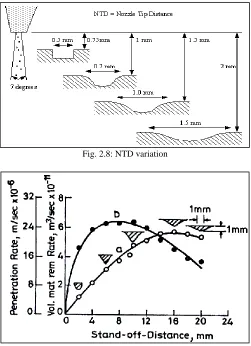
Effect of Standoff distance
Standoff distance is defined as the distance between the face of the nozzle and the work surface of the workpiece.SOD has been found to have a considerable effect on the work material and accuracy. A large SODresults in flaring of the jetwhich leads to pooraccuracy.
Fig. 2.8: NTD variation
Fig. 2.9: change in penetration rate & volume of material remove
Above graph shows the change in penetration rate & volume of material removed with a change in standoff distance. It is clear from the figure that MRR increases with nozzle tip distance or Standoff distance up to the certain distance and then decreases. Penetration rate also increases with SOD and then decreases. The decrease in SOD improves accuracy, decreases kerf width, and reduces taper in the machined groove. However light operation like cleaning, frosting etc is conducted with large SOD say 12.5 to 75mm.
IV. CONCLUSION
For Higher precision work higher pressure and lower standoff distance are adopted to attain a higher accuracy and penetration rate for AJM.
The Higher stand off distance is preferable where material removal is prime importance.
MRR increase with an increase in abrasive jet flow rate, mixing ratio, internal pressure, standoff distance under certain condition.
REFERENCES
[1] Jagadeesha T, Assistant Professor, Abrasive jet machining, National Institute of Technology, Calicut
[2] Rajeev Kumar, Gurdeep Singh Deol, C. S. Kalra, Vijay Kr Sharma, Analysis on Performance of Different Parameters during Abrasive Jet Machining by Taguchi Method, International Journal of Emerging Research in Management &Technology ISSN: 2278-9359 (Volume-3, Issue-8)
[3] http://mechteacher.com/process-parameters-of-abrasive-jet-machining/.
[4] A.P. Verma and G. K. Lal Publication “An experimental study of abrasive jet machining”, International Journal of Machine Tool Design and Research, Volume 24, Issue 1, 1984, Pages 19-29