ISSN: 2278-067X, Volume 1, Issue 10 (June 2012), PP.36-40
www.ijerd.com
Discrete Event Simulation for Increasing Productivity in Digital
Manufacturing
Dr. Y.Arunkumar
1, Mr. Rajashekar Patil
2, Dr. S. Mohankumar
31
Dept. of Industrial and Production Engineering, Malnad College of Engineering, Hassan-573 201, Karnataka, India,
2,3
Mechancial Engineering Department, SDM College of Engineering & Technology, Dharwad-580002, Karnataka, India,
Abstract—Manufacturing Systems provide one of the most important applications of simulation. Simulation has been used successfully as an aid in the design of new production facilities and as well to evaluate suggested improvements to existing systems. There are many simulation tools available for simulating activities of manufacturing, however the today’s complex manufacturing situation demands for the tool that has an excellent GUI, open architecture, reusability and interfacing capability with other software tools. In this paper the few capabilities available in the latest versions of discrete event simulation tool have been used to support digital factory and to increase the productivity of the manufacturing by considering few cases of manufacturing situations. The Tecnomatix plant simulation software with an interface developed through Microsoft Visual Basic and Oracle Data Base to support the simulation and manufacturing is discussed.
Keywords—Discrete Event Simulation, Tecnomatix, Visual Basic, Oracle, ODBC
I.
INTRODUCTION
Simulation is an important tool for planning, implementing, and operating complex manufacturing systems. Several trends in the global manufacturing such as increased product variety, product complexity, flexibility, shorter product cycles, shrinking lot sizes, competitive pressure demands for shorter planning cycles [3]. Simulation is an excellent tool where simpler methods no longer provide useful results. In addition, the number of technical components in many products and as a consequence also the requirements for corresponding assembly processes and logistics processes increases. These requirements can be managed only by using appropriate Digital Factory tools in the context of a product lifecycle management environment. Cutting inventory and throughput time by 20–60% and enhancing the productivity of existing production facilities by 15–20% can be achieved in real-life projects [2].
Today’s simulation tools provide key features such as a whole range of easy-to-use tools, necessary functionality, object orientation and inheritance to model, analyse, and maintain large and complex systems in an efficient way, and to determine optimized system parameters. It allows the users to develop, exchange/reuse, and maintain their own objects and libraries to increase modelling efficiency.
Optimization capabilities support users to optimize multiple system parameters at once like the number of transporters, monorail carriers, buffer/storage capacities, etc., taking into account multiple evaluation criteria like incre ased throughput, reduced stock, increased utilization, etc. Based on these accurate modelling capabilities and statistic analysis capabilities, typically an accuracy of at least 99% of the throughput values is achieved with the simulation models in real -life projects depending on the level of detail [1].
Many Optimisation tools such as bottleneck analyser, Sankey diagrams, Gantt charts, Layout optimizer, Genetic Algorithm wizards, Neural Network, Statistical tools, interfacing tools are embedded and available as objects for the users in the recent simulation software. With all these and powerful simulation programming language any complex model building, analysis and optimization is possible.
Even with all the required features built into simulation tools, model building requires special training. Simulation modelling and analysis is time consuming and expensive. Skimping on resources for modelling and analysis may result in a simulation model or analysis that is not sufficient for the task.
In this paper the recent version of the Tecnomatix Plant Simulation, an excellent discrete event simulation tool with all the latest features required to create simulation model is used to simulate the manufacturing system. An user friendly Graphical Interface is created using the Microsoft Visual Basic to simplify the model building activity. A popular and powerful database management system, Oracle is used to store the data related to simulation model is used. The important aspects of this work is the integration of three tools, A GUI, a data base management system and the simulation tool. The integration has been tested by considering a problem in manufacturing. This type of integration helps the collaborative manufacturing with the sharing and effective utilization of resources.
II.
DISCRETE
EVENT
SIMULATION
MODEL
Table 1. Details of the simulation model
No. of Shops :04 No. of Machines :18 No. of Families :10 No. of Parts :40
Parts : p1,p2,p3………p40
Shops: c1,c2,c3,c4
Families : F1,F2,F3,………F10
C1M1 Machine 1 of Shop C1
To perform the integration of the GUI, Data Base Management System and the Simulation tool a general batch manufacturing problem is considered. The details and terminology used in the model is shown in the table 1. Four shops with different set of machines, forty parts with different part routings, set up and processing times belonging to different family is considered. Figure 1 shows the simulation model created using Tecnomatix plant simulation. The Sankey diagram shows the part routing and the flow path density. The model is created using predefined objects such as Frame, Source, Singleproc, MU, Drain, Tablefile, Chart, Method, ODBC. In table 2. the details of the family, part routing and the processing machines details have been provided.
Table 2. Details of the family, parts and part routing
Family Name Parts Part Routings
F1 P1, P4, P7, P10 , P12 C1M C1M6 C2M1C2M8C3M8C4M5
F2 P16, P18, P19 , P20 C1M3C1M7 C3M3 C3M5C3M7C4M1
F3 P33, P35, P37 C1M2C1M9C2M3 C2M9C3M1C4M3
F4 P2, P6, P9,P11,P13 C1M1 C1M6C2M1 C2M8C3M8C4M5
F5 P21, P22, P23, P24 C1M3C1M7C3M3C3M5C3M7 C4M1 F6 P17, P34, P36, P38 C1M3C1M7C3M3C3M5C3M7C4M1
F7 P39, P40 C1M3C1M7C3M3C3M5C3M7 C4M1
F8 P3, P5, P8, P14,P15 C1M2C1M9C2M3C2M9C3M1C4M3
F9 P25,P27, P29,P31 C1M2C1M9C2M3C2M9C3M1C4M3
F10 P26,P28, P30, P32 C1M1C1M6C2M1C2M8C3M8C4M5
B. Processing and Setup Time for parts
1) Processing and Setup time for the parts is obtained using the Erlang distribution. The Erlang-distribution is the sum of k independent, exponentially distributed random numbers with the same argument beta. The realizations are non-negative real numbers [4]. The built in function of the following form is used to obtain the processing and setup time for the parts
2) Processing time function : z_erlang(1,5000,1000); 3) Setup time function : z_erlang(1,500,100);
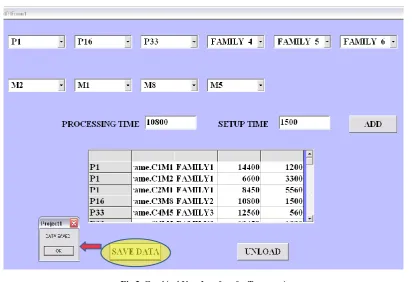
Fig 2. Graphical User Interface for Tecnomatix
III.
DATABASE
STRUCTURE
Table 3: details (table details stores the number of shops, machines, families and parts)
Field Description Field Name Data Type
No. of shops ns number (4) No. of machines nm number (4) No. of families nf number (4) No. of parts np number (4)
Table 4: shop_machine (table shop_machine stores the names of the shops and machines)
Field Description Field Name Data Type
shop name shop varchar2 (10) machine name machine varchar2 (10)
Table 5: family_parts (table family_parts stores the relation of family and parts)
Field Description Field Name Data Type
family name family varchar2 (10) part name parts varchar2 (10)
Table 6: part_routing (table part_routing stores the part routing and processing details-workplan)
Field Description Field Name Data Type
part name pname varchar2 (25) machine name mname varchar2 (25) family name fname varchar2 (25) Processing time in seconds processing_time varchar2 (25) Setup time in seconds setup_time varchar2 (25)
IV.
INTEGRATION
OF
TECNOMATIX,
VB
AND
ORACLE
C. Integration of GUI, Oracle Data base and Tecnomatix Plant Simulation
time details are input. All these details are stored in the Oracle database. The structure of the database to store these details is show in table 3,4,5 and 6
Once the entry of these details is completed the simulation model is automatically created by importing the details of the model from the data base using the ODBC object. The data imported are stored in the table files and this data is provided during the simulation run. The interface simplifies the modeling and simulation activity. In the method object used the data importing commands have been coded. The simulation can be executed using the event controller and the results are stored and exported for the statistical analysis and the reports are generated:
V.
THE
ODBC
INTERFACE
The ODBC interface allows to access ODBC data sources. In this work the ODBC interface for reading data from an oracle database and storing the results of simulation is used. The plant simulation provides the ODBC object that allows the database to be connected from a specified user and a server. The built in ODBC object in the plant simulation has all the necessary attributes to connect to the required database and the SQL commands to fetch the required data from the table using SimTalk.
VI.
RESULTS
AND
DISCUSSIONS
Two simulation models have been created. One without the buffer and one with the buffer. The performance measures such as makespan, throughput, utilization flow path are studied.
Makespan (Total completion time ) without the use of buffer 19:15:22:44.0000 Makespan (Total completion time ) with the use of buffer 16:06:41:40.0000
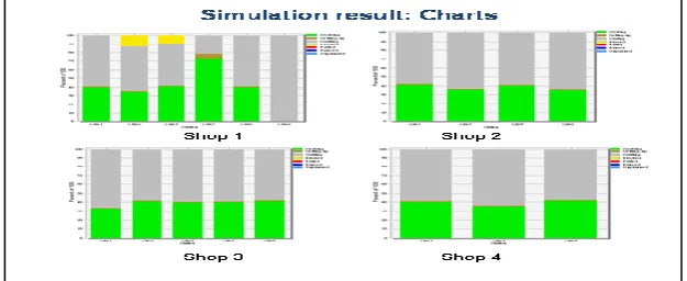
The makespan, total time to complete processing of all the jobs with and without the use of buffers have been computed. Simulation model gives the total completion time in DD:HH:MM:SS. It is clear that the use of buffer reduces total completion time more than 3 days and 15 hours. Such details are difficult to get manually and creating simulation model also is difficult to generate. The use of such interfacing tools makes job easier. Simulation results such as total working, setup, idle and blocking time of the machines of four shops is shown using the stacked column chart of fig. 3. The chart object of the Tecnomatix plant simulation is used to plot these charts.
Fig. 3 Stacked column charts showing the working, setup, idle and blocking time of the machines
VII.
CONCLUSIONS
Latest technical objects and features of the simulation tools simplify model building, analysis activities of any complex manufacturing problem. The open architecture, reusability and interfacing capabilities of the simulation software simplify the creation of user friendly interface. The resource sharing and collaborative work through the web integration can be achieved and the utilization of the expensive simulation tool can be increased.
REFERENCES
[1]. M. C. (Mike) Albrecht, P.E. (AZ), Introduction to Discrete Event Simulation, January 2010
[2]. Stefen Bangsow, Manufacturing simulation with plant simulation and SimTalk, 2010 Springer-Verlag Berlin Heidelberg
[3]. B. Kadar, A. Pfeiffer, L Monostoril, Discrete event simulation for supporting production planning and scheduling decisions in digital factories, research paper of Computer and Automation Research Institute, Hungarian Academy of Sciences, Budapest, Hungary
[4]. S. G. Ponnambalam1, P. Aravindan1 and K. Raghu Rami Reddy, Analysis of Group-Scheduling Heuristics in a Manufacturing Cell, Int J Adv Manuf Technol (1999) 15:914–932
[5]. Kenneth Musselman, Jean O.Reilly, Steven Duket, The role of simulation in advanced planning and scheduling, Proceedings of the 2002 Winter Simulation Conference