Design of Compact U-Shaped Microstrip Slot
Antenna for WLAN, Wimax and Radar
Applications using ADS Software
C. Pricilla Paul Dr. M. Baritha Begum
PG Student Assistant Professor
Saranathan College of Engineering,Trichy, India Saranathan College of Engineering,Trichy, India
Abstract
In present years Micro strip patch antenna is predominately worn in numerous wireless communication system and Radar applications. In this paper a projected configuration of U shaped micro strip slot antenna for high frequency application is designed and simulated. This projected Antenna with a reduced size of 28.3 x 37 mm is intended with FR4 Substrate by using the micro strip line feeding techniques for Micro strip patch is with a stamped ‘U’ shaped slot. This Antenna provides a preferential impedance Bandwidth along with an uni directional Radiation Pattern. The antenna is intended for operating frequency 6.33 GHz and dielectric constant 4.4 by using advanced design Systems simulation software. Projected antenna is deliberate for wireless local area network (WLan).
Keywords: Advanced design Systems, Return Loss, wireless local area network, U shape micro strip slot
________________________________________________________________________________________________________
I. INTRODUCTION
Micro strip antenna (MSA) realize many applications in the devise of wireless communication systems an antenna is distinct by the IEEE as a “transmitting or receiving system that is intended to emit or collect electromagnetic waves”. Now a days there is a insist for wireless and transportable devices are available to increase for the wireless applications like WLAN, Wi-Fi, WiMAX, and etc. An antenna can be several shape or different size. It has numerous advantages such as low profile, firmness, easy to produce on chips, low cost easy and installation etc but it has a few drawback of narrow band width which proved to be a confront for engineers to meet very high data rate for a variety of wide band application. The band width of antenna can be enlarged by a range of techniques such as cutting slot, different shape of antenna and intensifying the depth of substrate with small dielectric constant. By micro strip line feeding moving the different location of feeding point thus we obtained maximized bandwidth.
II. LITERATURE SURVEY
A square opening, a couple of L-strips, and the monopole radiator are used to motivate three different resonances point in [1]. In paper [2], a micro strip line feeding techniques along with, a thick substrate, and a ground plane on which some simple openings are imprinted to accomplish tri band operation. The fork-type ground is using along with non-uniform meandering of line and are anticipated triple band Wireless local area network applications in paper [3]. A twisted M-shaped patch is worn the longer arm of the patch to devise the triple band antenna, for the purpose of compactness in ref [4]. The Inverted L-slot patch with a defect ground plane is used for triple-band operation in paper [5], An F-shaped micro strip slit antenna with both undefined and small-ended slits linked by a metal by means for getting a micro strip line is oppressed for WLAN and WiMAX multiple input multiple output systems in ref [7]. A monopole antenna with two rectangular corners engraves off and two inverted L slots are imprinted to accomplish three resonant modes for tri band operation is presented in paper [8]. A crooked coplanar stripe fed configuration was instigating in ref paper [9, Meta material transmission lines and MTM inspired reactive loading methods are used in [10] and [11]. In ref paper [14], the antenna can be able to envelop the obligatory bands with a tremendously miniature form factor with the assist of the MTM motivated reactive loading and L cut shaped slot. Even though, every reported antennas reveal triple-band performance. In this communication, a compressed F shaped planar antenna is projected and intended for wireless communication systems with the intention of supporting the triple-band WLAN/WiMAX applications. The anticipated antenna consists of two F shaped openings of the identical size that are etc. on a rectangular patch to accomplish multi band operation.
III. ANTENNA DESIGN
Input power to the patch. A U-Shaped opening facilitates with the purpose of the patch Antenna to radiate at 6.33 GHz and 9.1 GHz frequencies which also provide the benefits better gain and also boost up the efficiency. The general structure of the proposed antenna is given below.
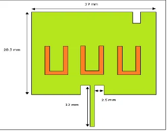
Fig. 1: proposed U shaped slotted micro strip patch antenna
Dielectric constant is distinct as the determining of extent to which an EM wave is slowed down at the same time as it travels throughout the material. consequently, a small value of dielectric constant material is selected to keep away from the storage of charge in the dielectric substrate, Electro Magnetic wave should be contemplate through the substrate and it is not engrossed. The very thin substrates with higher dielectric constant which causes the reduction of efficiency, lesser band widths and slighter element sizes, the excitation of surface waves that decline the radiation pattern. To raise the narrow bandwidth and radiation efficiency of patch antenna, slotted patch antennas or stacked can be used. If the quality factor of the antenna is small so we are used the small value of dielectric constant.
IV. DIMENSION OF ANTENNA
The devise parameters are specified below which conveys the dimensions between patch u shaped slot, and the feed line. The feed width and gap are designed to get 50 ohm input impedance. The projected U-Shaped patch Antenna geometry are given below.
Width of the patch w = 37 mm Length of the patch L = 28.3 mm Height of the substrate h = 1.6 mm Dielectric constant = 4.4
Length between patch and feed line =4.2 mm Width between patch and feed line =2.5 mm Width of the ground plane = 30 mm
Length of the ground plane = 30 mm
Width of the slot =1mm Length of the slot=7.9 mm Thickness of the u slot = 0.9 mm Length of the upper u slot=3.5 mm.
Micro strip patch antennas can be feed by a different of methods. These methods be able to be secret into two types: one is contacting and another one is non-contacting.
1) In contacting Technique, the RF input power is contacting directly between fed to the radiating patch using a connecting element such as a microstrip line.
V. SIMULATION RESULTS
Our main objective of this work is to intend and extend a U shaped micro strip based antenna, which can operates for wireless applications. The ADS software is used to figure the power, gain, radiation pattern, and return loss of the antenna. Reflection coefficient s11 is greatly depends on the source and load impedance. It shows with the intention of how much the transmission line is well matched. But the load impedance and source impedance are having the same value. For greatest power transfer of the Return Loss should be present less as much as achievable. This conveys that the that the ratio PR\PT should be as miniature as possible otherwise or articulated in dB, the return loss should be as huge in negative number as achievable
Fig. 2: Return loss at 6.63 GHz and 9.12 GHz Frequencies
The below image Figure out the return loss which conveys the information that the loss throughout the radiation of antenna is very a smaller amount thus the efficiency is increased. The antenna resonates at frequency of 6.63 GHz and 9.125 GHz with low return loss of -39 dBi and -22 dBi respectively.
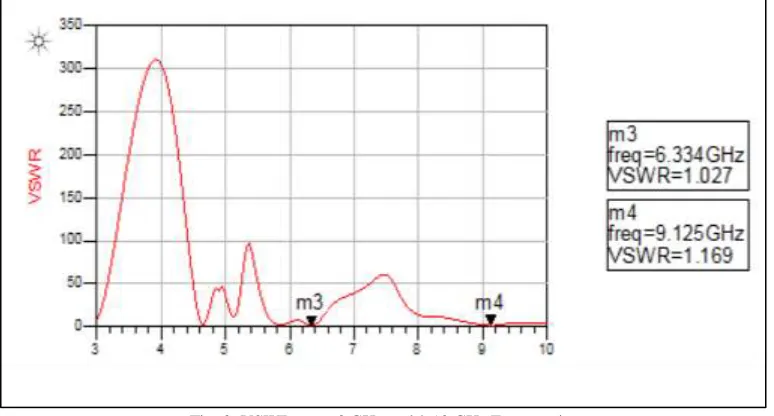
Fig. 3: VSWR at 6.63 GHz and 9.12 GHz Frequencies
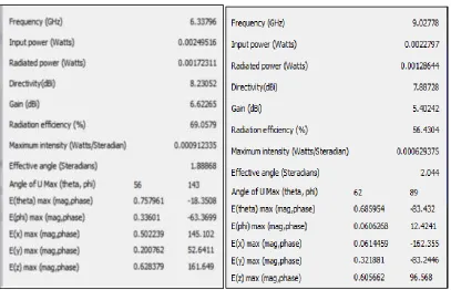
Fig. 4: Gain and Directivity for 6.33 GHz Fig. 5: Gain and Directivity for 9.12 GHz
Fig. 6: Average current density at 6.33 GHz Fig. 7: Average current density at 9.12 GHz
More specifically it is a plot of the power radiated from an antenna per unit solid angle which is nothing but the radiation intensity.
VI. CONCLUSION
In this paper a microstrip U shaped antenna is successfully designed at a resonant frequency of 6.63 GHz. Micro strip antenna s has become a rapidly growing area of research such as light weight, compact size and various applications. A compact triple U shaped microstrip patch antenna is designed for Wireless communication application. Antenna gain is 6.62 d B , Directivity is 8.23 and the Radiation Efficiency is also increased.
REFERENCES
[1] W. Hu, Y.-Z. Yin, P. Fei, and X. Yang, “Compact tri band square-slot antenna with symmetrical L-strips for WLAN/WiMAX applications,” IEEE Antennas Wireless Propag. Lett., vol. 10, no. pp. 462–465, May 2011.
[2] L. Dang, Z. Y. Lei, Y. J. Xie, G. L. Ning, and J. Fan, “A compact microstrip slot triple-band antenna for WLAN/WiMAX applications,”IEEE Antennas Wireless Propag. Lett., vol. 9, pp. 1178–1181, Dec. 2010.
[3] C.-M. Wu, C.-N. Chiu, and C.-K. Hsu, “A new non-uniform meandered and fork-type grounded antenna for triple-band WLAN applications,”IEEE Antenna Wireless Propag. Lett., vol. 5, no. 1, pp. 346–349, Dec.2006.
[4] L. Peng, C.-L. Ruan, and X.-H.Wu., “Design and operation of dual/triple band asymmetric M-shaped microstrip patch antennas,” IEEE Trans. Antennas Propag., vol. 9, pp. 1069–1072, Dec. 2010.
[5] A. Kunwar, A. K. Gautam, and B. K. Kanaujia, “Inverted L-slot triple band antenna with defected ground structure for WLAN and WiMAX applications,” Int. J. Microw. Wireless Technol., Feb. 2, 2016, doi: 10.1017/S1759078715001105 R. Karimian, H. Oraizi, S. Fakhte, and M. Farahani, “Novel F-shaped quad-band printed slot antenna for WLAN and WiMAX MIMO systems, ”IEEE Antennas Wireless Propag. Lett., vol. 12, pp. 405–408, Mar. 2013. [6] H. Chen, X. Yang, Y. Z. Yin, S. T. Fan, and J. J. Wu, “Tri band planar monopole antenna with compact radiator for WLAN/WiMAX applications,” IEEE
Antennas Wireless Propag. Lett., vol. 12, pp. 1440–1443, Oct. 2013.
[7] X. Li, X.-W. Shi, W. Hu, P. Fei, and J.-F. Yu, “Compact tri band ACS-fed monopole antenna employing open-ended slots for wireless communication,” IEEE Trans. Antennas Propag., vol. 12, pp. 388–391, Mar. 2013.
[8] H. Huang, Y. Liu, S. Zhang, and S. Gong, “Multiband meta material loaded monopole antenna for WLAN/WiMAX applications,” IEEE Antennas Wireless Propag. Lett., vol. 14, pp. 662–665, Feb. 2015.
[9] C. Zhou, G. Wang, J. Liang, Y. Wang, and B. Zong, “Broadband antenna employing simplified MTLs for WLAN/WiMAX applications,” IEEE Antennas Wireless Propag. Lett., vol. 14, pp. 595–598, Apr. 2014.
[10] S. Joshi, A. K. Gautam, and R. Upadhyay, “Frequency agile triple band microstrip antenna for WLAN/WiMAX application,” Int. J. Future Comput. Commun., vol. 3, pp. 258–261, 2014.
[11] P. Liu, Y. Zou, B. Xie, X. Liu, and B. Sun, “Compact CPW-fed tri band printed antenna with meandering split-ring slot for WLAN/WiMAX applications,” IEEE Antennas Wireless Propag. Lett., vol. 11, pp. 1242–1245, Nov. 2012.
[12] C.-M. Peng, I.-F. Chen, and J.-W. Yeh, “Printed broadband asymmetric dual-loop antenna for WLAN/WiMAX applications,” IEEE Antennas Wireless Propag. Lett., vol. 12, pp. 898–901, Jul. 2013.
[13] C. A. Balanis, Antenna Theory Analysis and Design, 3rd ed. Hoboken, NJ, USA: Wiley, 2005
[14] Kawei Qian and Xiaohong Tang, “Compact LTCC dual band circularly polarized perturbed hexagonal micro strip antenna,” IEEE Antennas and Wireless Propagation Letters, Vol. 10 pp. 1212-1215,2011
[15] K. Kumar and N. Guna sekaran, “A novel wideband slotted mm wave microstrip patch antenna,” Proc. IEEE Vol. 987-1,pp.10-14, 2011.
[16] A. Sen, J. S. Roy and S.R. Bhadra Chaudhuri,“ Investigation on a dual-frequency microstrip antenna for wireless applications,” Proc. IEEE. Vol. 978-1, 2009.