Development of a Discrete Event Controller
Supervisor using a Hybrid Matrix Formulation
with Fuzzy Logic Conflict Resolution
Jose Mireles Jr.1, Frank L. Lewis2, Roberto C. Ambrosio1, Edgar Martínez1 1Universidad Autónoma de Ciudad Juárez, Chih, México
2University of Texas at Arlington, TX, USA
Emails: *[email protected], [email protected], [email protected], [email protected]
Abstract— Using a patented matrix formulation, a Discrete Event (DE) controller is designed for a manufacturing cell. The DE controller can directly be implemented from standard manufacturing tools such as the Bill of Materials or the assembly tree. The matrices also make it straightforward to actually implement the DE controller for sequencing the jobs and assigning the resources. We use virtual places to interact with our machine resources to control and supervise the DE system as a transient timed place Petri Net (PN) system. This modified PN together with marking transition equation provides a complete dynamical description of a Discrete Event System (DES). In this paper, we include to our DE supervisor several new structures that contain all decision making attributes for each part and resource jobs in the Manufacturing processes. The versatility of this DE controller permits implementing different methodologies for decision making and conflict resolution, including artificial intelligence techniques, as well as optimization of the resource assignment and part throughput. This paper shows an example of such versatility included in the supervisor by showing a hybrid decision making development.
Index Terms— Petri nets, Virtual Places, Timed Place Petri Net, Discrete Event Systems, Reentrant flow lines, Flexible manufacturing systems, Fuzzy Logic.
I. INTRODUCTION
For analysis, modeling and control of manufacturing systems, resource sharing for proper job sequencing has always been a main problem. While some resources manipulate or machine single parts in a DES, others manipulate or machine multiple parts for several products in the manufacturing process. If jobs are not correctly sequenced in the latter case, serious problems in the performance of the DES can be obtained, including blocking and system deadlock [Banaszak et al. 90, Mireles et al. 03]. Therefore, it is very important that the workcell controller properly sequences jobs and assigns resources.
To properly sequence jobs and dispatch resources, one of the base tools that is extensively used is Petri nets (PN) [Peterson 81, Murata 89, Desrochers 90, Zhou et al. 92-93]. This paper uses a Discrete Event Controller (DEC) based on the decision making matrix formulation introduced in [Lewis 92, Lewis et al. 93], and
implemented at [Mireles et al. 01], which can control and sequence jobs like PNs. Important features of this matrix formulation are that it uses a logical algebra, not the Max/Plus algebra [Cofer et al. 92], and that it can be described directly from standard manufacturing tools that detail product requirements, job sequencing [Eppinger 90, Steward 81] and resource requirements [Kusiak et al. 92]. That is, this matrix-based DEC can be directly written down from the bill of materials or the partial assembly tree. Also, using the flexibility of this matrix formulation we modified its matrices and included Virtual Places to control job dispatching in a Timed Placed PN fashion [Mireles et al. 04], to provide a complete dynamical description of DE System (DES.) This description of the DES takes into account a vector Time which was used in a simulation scheme in [Mireles et al. 01ab]. It can be shown that this DEC is a formalized version of both the “Top-Down” and the “Bottom-Up” PN design approach [Desrochers 90; Zhou et al. 92-93].
Since the DE supervisor needs detailed information of the pending jobs, and the attributes of the in-process parts into its decision making algorithms, in this paper we integrate new structures that maintain all attributes for each part and resource jobs in the Manufacturing processes. These attributes on independent parts (or tokens in PN algebra/notation) are those needed for the FIFO, FBFS, LBFS, EDD, LS, and other Heuristic scheduling and artificial intelligence decision making algorithms [Kusiak 00, Xiong et.al 95]. Examples of few of these attributes are arrival time of part into cell, time waiting in current buffer, expected finish time, cost, product line, and others.
II. MATRIX-BASED DISCRETE EVENT CONTROLLER (DEC)
A novel DEC for manufacturing workcells was described in [Lewis et al. 92-93, Pastravanu et al. 94, Tacconi et al. 97]. This DEC is based on matrices, and it was shown to have important advantages in design, flexibility and computer simulation. In this paper, we show that it also allows commensurate advantages in actual implementation on a practical robotic cell. Following the same notation used in [Lewis et al. 93], the definition of the variables of the Discrete Event System is as follows. Let v be the set of different tasks or resource jobs used in the system, r the set of resources that implement/perform the tasks, u the set of inputs or parts entering the DES and y the set of outputs or finished parts/products of the DES. The DEC Model State Equation is then described as
v r u uc c
x =F ⊗ ⊕v F ⊗ ⊕r F ⊗ ⊕u F ⊗u (1) Where
x
is the task or state logic vector Fv is the job sequencing matrix Fr is the resource requirements matrix Fu is the input matrixFuc is the conflict resolution matrix, and uc is a conflict resolution vector.
This DEC equation is performed in the AND/OR algebra. That is, multiplication
⊗
represents logical “AND,” addition⊕
represents logical “OR,” and the over-bar means logical negation. From the model state equation, the following four interpretations are obtained. The job sequencing matrix Fv reflects the states to be launched based on the current finished jobs. It is the matrix used by [Steward 81] and others [Whitney et al. 91]. The resource requirement matrix Frrepresents the set of resources needed to fire possible job states. It is the matrix used by [Kusiak et.al 92]. The input matrix Fu determines initial states fired from the input parts. The conflict resolution matrix Fucprioritizes states launched from the dispatching input u, which has to be derived via some decision making algorithm [Panwalker et al. 77, Kusiak 00, Elsayed et al. 94]. The relationship of these matrices with Petri-Nets is shown in the next section. Discrete Event matrices are combined to give activity completion (2) and activity start matrices (3) which are the key components of the incidence matrix of an ON structure.[
u v r y]
F
=
F F F F
(2) T[
u v r y]
S
=
S S S S
(3)III. MATRIX FORMULATION AND PETRI NETS
There is a very close relationship between the DEC just described and PNs. The Incidence Matrix [Peterson 81] of the PN is obtained after defining the activity
completion matrix and the activity start matrix. Then, the PN’s Incidence Matrix is defined as
] ,
, ,
[ y
T y r T r v T v u T u T
F S F S F S F S F S
M= − = − − − − (4)
If we define X containing the elements x (the state controller vector), and A as the set of activities containing the vectors v and r, i.e. ( A=[ v r ]T), then it can be shown
that (
A X F S
, ,
T,
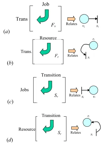
) is a Petri Net [Pastravanu et al. 94]. This allows one to directly draw the PN of a system given the matrices F and S.The elements of matrices F and S, which are ‘zero’ or ‘one’, can be related directly with a PN representing the Reentrant Flow Line (RFL). Use figure 1 as a referencefor the following explanation. In fact, FTis the PN input incidence matrix and S is the PN output incidence matrix. The fi,jelements of Fv which are set to ‘one’, state that to fire transition xi, the job vjneeds to be finished. The fi,jelements of Fr set to ‘one’, indicate that to fire transition xi, the resource rjneeds to be available. The fi,jelements of Sv set to ‘one’, indicate that to start job vj, the transition xi needs to be finished. The set of fi,j elements from Sr are set to ‘one’ to indicate that the resource riis released after the transition xjis finished. If the marking vector m(t) from a PN is defined as
( ) [ ( ) , ( ) , ( ) ,T T T ( ) , ( ) ]T T T D
m t = u t v t r t u t vp t (5) for a specific time iteration t, then the PN marking transition equation [Peterson 81] is
( 1) ( ) T ( ) [ T ] ( )
m t+ =m t +M x m t= + S −F x t (6)
IV.MODELING AND INDUSTRIAL WORKCELL
(a)
Job
Trans
Fv Relates vj xi
(b)
Relates x
i
Trans.
Fr
Resource rj
(c)
Relates x j vi
Transition Jobs
Sv
(d)
Relates x
i
Transition
Sr
Resource
rj
Figure 1. Relationship of the matrices with PN: (a) job-sequencing matrix Fv, (b) resource requirement matrix Fr, (c)
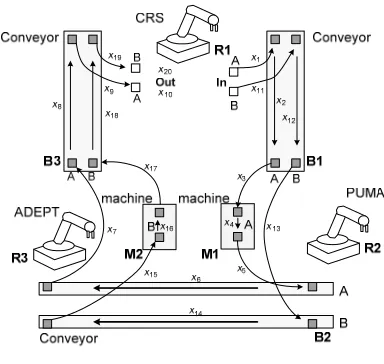
The Intelligent Material Handling (IMH) cell at the University of Texas at Arlington’s ARRI is composed of three robots, three conveyors, ten sensors and two machines (shown in figure 2.) The IMH cell is a multipart RFL problem because some resources are required more than once to manufacture products, which re-use these resour-ces. See [Kumar 93] for notions on analysis and shared resource dispatching in RFL. The DEC matrices in (1) can be directly written down by considering the RFL, or the resource assignment and the bill of materials [Harris 98]. This cell is an excellent platform to experiment with different conflict problems, like the one discussed in this work. Different configuration of re-entrant flowline problems can be accomplished with this structure. The image and the part flowline of the IMH cell are depicted in Figures 2 and 3, respectively. For this specific layout the robot defined as R1 (a CRS robot) can perform four different tasks, ⎜J(R1)⎜=4. Two tasks (R1u1 and R1u2) are related to picking up part-types A and B from the input-parts area, which are to be placed on the conveyor denoted B1. The other two tasks (R1u3 and R1u4) are associated with picking up final products A and B from conveyor B3 and placing them in the output-parts area. A PUMA robot, R2, performs three different tasks, ⎜J(R2)⎜=3: pick up parts A from conveyor B1 to place them in machine M1 (R2u1), pick up parts B from conveyor B1 to place them on conveyor B2 (R2u2), and pick up parts A from M1 to be placed on conveyor B2 (R2u3). The Adept robot, R3, also performs three different tasks, ⎜J(R3)⎜=3: pick up parts A from conveyor B2, to place them on conveyor B3 (R3u1), pick up parts B from conveyor B2 to place them in machine M2 (R3u2), and pick up parts B from M2 to be placed on conveyor B3 (R3u3).
Figure 2. Intelligent Material Handling (IMH) cell.
Due to the existence of shared resources this configuration of the IMH cell presents a dispatching problem. Both phenomena, conflict and deadlock, may occur in the case of an inappropriate dispatching strategy. Deadlock prevention and avoidance will not be discussed in this paper, due that we concentrate our attention on the hybrid supervision of the combination of matrix formulation and the fuzzy conflict resolution strategy.
Figure 3. A layout with the parts paths of the IMH-cell used in a case study
The matrix model can be directly written down from Figure 3, which shows both job sequencing and resource assignment. From Figure 3 one can find that the system is described with 20 rules. The job sets that correspond with job sequences for two part paths and the set of resources are defined as follows:
part A path: J1 = {R1u1, B1AS, R2u1, M1P, R2u3,
B2AS, R3u1, B3AS, R1u3}
part B path: J2 = {R1u2, B1BS, R2u2, B2BS, R3u2, M2P,
R3u3, B3BS, R1u4}
set of resources: R = {B1AA, B1BA, M1A, B2BA, B2AA, M2A, B3AA, B3BA, R1, R2, R3} with a set of shared resources Rs={R1, R2, R3}.
The description of jobs performed by nonshared resources is given in Table 1.
Table 1. Description of jobs in IMH cell
Notation Description
B1AS transporting part A on conveyor B1
M1P processing part A in machine M1
B2AS transporting part A on conveyor B2
B3AS transporting part A on conveyor B3
B1BS transporting part B on conveyor B1
B2BS transporting part B on conveyor B1
M2P processing part B in machine M2
The nomenclature used in the IMH is as follows: “RXuY” means job “Y” is executed by robot “X”, “BxyS” means that product type “y” is transported by conveyor “x”, “MxP” stands for machine “x” is busy, “BxyA” means that conveyor “x” is available for product type “y”, “MxA” denotes machine “x” is available, “RxA” stands for robot “x” is idle. Note that instead of having three different resources for conveyors B1, B2 and B3, six different resources are used. This is because of the two different materials paths on each conveyor. For example, conveyor B1 has paths B1A and B1B, which are denoted as B1AA and B1BA when they are available, and denoted as B1AS and B1BS when they are carrying material.
Given the system layout and the system description, one can determine the system matrices, herein shown “graphicaly” with black and white rectangles, indicating “1” and “0”, respectively.
The last three columns of Fr correspond to the shared resources R1, R2 and R3. From the number of 1s in those columns we see that R1 is involved in four conflicting rules (possible conflict if any combination of states x1, x9, x11 and x19 fire at the same time), while each of the
remaining robots, R2 and R3, contribute in three, which finally gives ten state combinations requiring conflict rules. According to the definition, Fd is constructed by creating a new column for each “1” appearing in Fr for the shared resources, hence, the dispatching matrix will have 10 columns, shown as follows:
It should be noted that columns of Fd have been rearranged in order to group components of the dispatching vector that belong to the same shared resource, for instance, the last column for Fr has been converted to create three columns in Fd. Specifically, R1 is controlled with ud1, ud2, ud3 and ud4, R2 with ud5, ud6
and ud7, and R3 with ud8, ud9andud10.
V.SHARED-RESOURCES IN CONFLICT
One of the strengths of the matrix-based DEC is that different shared–resources conflict resolution strategies can be implemented by suitably computing uc, the
conflict resolution input. This DEC is capable to apply different conflict resolution strategies for the shared-resources by monitoring via matrix Fuc and controlling
the input vector uc [Pastravanu 94].
Shared-resource dispatching in multi-path reentrant flow lines is not an easy topic. Depending on the way one selects the conflict resolution strategy to generate uc,
different dispatching rules can be selected. These rules fall mainly into three categories: Part/Machine, Buffer, and Hybrid (part-buffer) [Panwalker et al. 77, Kumar 93, Lewis et al. 93]. Examples for the Buffer category are First-In-First-Out (FIFO), First-Buffer-First-Serve (FBFS), Last Buffer-First Serve (LBLS), Shortest Non-Full Queue, Shortest Remaining Capacity, and Shortest Queue Next. Examples for the Part/Machine category are Earliest-Due-Date (EDD), Least-Slack (LS), Shortest Imminent Operation Time, Largest Imminent Operation Time, Shortest Remaining Processing Time (SRPT), Largest Remaining Processing Time, Machine with Least Work and Least Slack Time.
In this paper we use a Fuzzy Logic conflict resolution approach combining Hybridly the matrix formulation of states to look for an optimal production throughput. Also, this approach uses also a dispatching rule that avoids first order deadlocks, discussed in previous work [Mireles et al. 01-03ab]. However, in this work, we do focus in the development of the augmented DEC which makes it easy to implement any dispatching rule desired, including this intelligent dispatching hybrid rule for conflicted parts, buffers, and machines.
Sv =
Fv = Fu =
SyT= Fr =
Sr =
VI.HYBRID DISCRETE EVENT CONTROLLER FOR PROPER
DECISION MAKING
In the presence of job sequencing conflicts in manufacturing cells, the Petri Net tool itself provides through the enabled transitions the possible firing of jobs that are in conflict for particular resources. Refer to figure 4, showing a simplified PN example for further problem definition. Since for this case enabled transitions r2•, put
in conflict to resource r2, a decision must be made and
decide which of the resources/buffers r1 or r3 should be
released.
By controlling the marking on vector uc, only one
transition from the set of conflicted transitions can be fired (i.e. leaving only one token in either uc1 or uc2.) This
decision could be made based on the preference on the resource to be released, but also on the preference of the part to be released among all parts from places v1 and v3.
In large manufacturing processes, including Semiconductor manufacturing processes, this decision is made based on parts/wafers, and its attributes. This means that it is desired to include more information in the marking vector, m(t) (5), since not only the number of ‘tokens’/parts per buffer, or job, are important, but also the independent attributes of parts such as arrival time to the cell, cost, waiting time, and its expected end of process time.
Figure 4. Petri Net structure with conflict in r2.
Then, it is required that all part attribute information must be conserved and maintained on each element of v(t)T, the
pending or finished jobs of the entire cell. This can be easily maintained by enhancing this vector through v(t,k)T, where k stands for the kth part in the set of parts
for each resource job vector v(t)T. For example.
Considering figure 4, the marking in that state t of this PN for job v1 is three (each job type vk(t) is a member of v(t)T.) Then, each part in v
k(t) can be particularized
though v(t,k), since
vj(t) =
U
vj(t,k) = { vj(t,1), vj(t,2), …, vj(t,n)}, (7)where n is the number of parts in job or buffer vj(t).
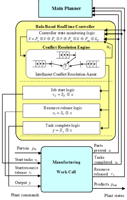
Then, we propose that our main DE Supervisor be divided as shown in figure 5. The main planner decides on the system supervisor structure of matrix formulation, creating indirectly the entire PN system structure. Then, the matrix controller structure calculates the task or state logic vector, (1), which determines the possible firing of jobs of resources.
In case of any conflict on jobs, a conflict resolution engine takes its decision based on the attributes of the parts which uses a fuzzy logic approach. This engine might consider intelligent decision making by combining different standard conflict resolution rules, and by considering each attribute of parts in conflicted buffers. In this work, in order to demonstrate the performance of the cell, we combined the following resolution techniques: FIFO, LS, EDD, and SRPT.
In order to define the way we combine these resolution techniques, consider the following definitions:
1) define Resol( type , vj(t) ), as the conflict resolution
type technique to be applied to all
available/machined parts in vj(t). The outcome of this
function is the set
[vj(t,k), w], (8)
where vj(t,k) is the part that conflict resolution type
opted, and w is the percentage weight that this conflict resolution routine weighted the part vj(t,k)
over the others.
2) define Conflict( rj(t) ), as the function that returns the
set of jobs {vj(t)} in conflict with this resource (this
is a row vector). (9)
Then, for each machine rj(t) we calculate the matrix Resol( type , Conflict(rj(t)) )T. For the r2 resource from
our conflict example, this matrix has the following format:
r1
v2
u1 v1 o3 uc1 r2
uc2 v3
u2 v4 o2
r3
Resol(FIFO, Conflict(r2(t)) )
Resol(LS, Conflict(r2(t)) )
Resol(EDD, Conflict(r2(t)) )
Resol(SRPT, Conflict(r2(t)) )
Resol (FIFO, v1(t) ) Resol (FIFO, v3(t) )
Resol (LS, v1(t) ) Resol (LS, v3(t) )
Resol (EDD, v1(t) ) Resol (EDD, v3(t) )
Resol (SRPT, v1(t) ) Resol (SRPT, v3(t) )
{v1(t, 1), 0.35} {v3(t, 1), 0.58} {v1(t, 3), 0.45} {v3(t, 2), 0.60} {v1(t, 2), 0.48} {v3(t, 2), 0.80} {v1(t, 1), 0.39} {v3(t, 1), 0.67}
Figure 6 represents the classes written in C++ for each place and each token contained in such a place. Also, internal functions of these classes are shown.
Note.- we assumed some attributes shown above on each part on jobs/buffers v1 and v2, and calculate for each of
the resolution functions the following outcomes: the outcome for conflict resolution type FIFO in job v1 was
v1(t,1) (the first part in buffer v1,) with a weighted wining
gain of 0.35; the outcome for conflict resolution type LS in job v1 was v1(t,3) with a weighted wining gain of 0.45;
etc.
Notice that this matrix can help us decide not only among job types v1(t) and v3(t), but among parts from these job
type/buffers. This matrix resolution scheme is the input for our intelligent hybrid resolution engine, which in this case we are using a Fuzzy logic algorithm, that decides for the best vj(t,k) part to dispatch.
VII. IMPLEMENTATION OF THE DEC ON THE IMH
The DEC was implemented using eqs. (1)-(8) in LabWindows text based programming environment working on C platform. To run several process at one time we included the concept of multithreading which
allowed us to communicate between different resources at the same time. This allow us to monitor multithreaded processes, which control the jobs from each robot, machining jobs and the transfer of parts through conveyors, without the need to perform procedural programming to monitor each resource. The Petri Net structure of this case problem developed in the IMH cell is shown in figure 5.
We modified this PN structure and included the Virtual Places as discussed in [Mireles et al. 04]. We have five threads for the three robots and two machines and a main thread which does the matrix formulation for the DEC. The main supervisor considers the conditions for the virtual places and always keeps a track of the jobs being performed by the robots and the machines. This PC-based IMH controller has three serial ports that interact with the three robots of the IMH cell, as well as a DAQ card. The DAQ card receives discrete signals from capacitive proximity sensors, which sense parts within the IMH cell, and also sends discrete signals to the machines to initialize jobs.
VIII. FUZZY LOGIC RESOLUTION ENGINE
The resulting matrix, as the example shown in section 4.2, is the input to this Fuzzy engine, in the form of degree of validity of input rules. The engine consists on creating and comparing defuzzificated membership functions among all parts in conflict. Each membership function (MF) associated to a part is an expert comparison of the level of importance of the scheduling resolution techniques used (in our case, among resolution techniques FIFO, LS, EDD, and SRPT.) An example of one of the defuzzificated MFs associated to part v3(t, 2) is
shown in figure 7. Here we are showing different levels of importance among std. resolution techniques (having EDD higher, and SRPT lower level of importance.)
Figure 7. Membership function for v3(t, 2).
Then, for each part from vj(t,k) found in the matrix
Resol[type,Conflict(rj(t))]T, we calculate the
center-of-area (or centroide), shown as φ(vj(t,k)) in figure 7 for part v3(t,2). Then, by obtaining the higher φ(vj(t,k)) among the
parts disputing resource rj(t), we can have an outcome for a mixed resolution technique. However, we decided to include one more Fuzzy decision level in this work. As you might notice, earlier MF function gives priority to EDD resolution technique. But, what if one vj(t,k) part has two or more appearances in the matrix resolution used with out showing any in cells Resol (EDD, vj(t,k))? This is, a part should compete if it has won over two or more conflict resolution among SRPT, FIFO, and LS, vs. competing with a part having only won in EDD.
=
=
Figure 6. Interpretation of classes for each place in the Petri Net, and each token in places.
SRPT FIFO LS EDD 0.80
0.60 v3(t, 2)
Figure 8. Final MF for v3(t, 2).
Therefore, in order to give importance to parts that have won more than once conflict resolution technique among the ones having won only one type, we used a second MF like the one shown in figure 8. This is, the final conflict is defined by the locating the highest weight w, which is the centroide obtained from this 2nd MF. For
the example shown in PN from figure 4, the best outcome is to release part v3(t, 2) from job v3.
IX. CONCLUSIONS
The decision making matrix formulation controller supervisor proposed in [Lewis et al. 93, Mireles et al. 01], which provides the capability to analyze and control Discrete Event (DE) systems, was augmented through the addition of new hybrid supervisory structures to facilitate implementation of more sophisticated and intelligent conflict resolution techniques for manufacturing cells. Through this addition, we developed a matrix combination of standard manufacturing scheduling rules. Such a matrix formulation makes it possible to find a more optimal throughput and better performance of workcells. In this paper, using this matrix form, we show an implementation of a hybrid formulation combining matrices and Fuzzy Logic for decision rules and for better performance of workcells. The development of this DE supervisor was written in C code using the LabWindows© platform to manipulate and sequence a laboratory workcell composed of three robots, three conveyors, and two machining stations. Further work on more complex systems having shared resources, routing jobs, and deadlock resolution rules will be performed.
REFERENCES
[1] Banaszak Z. A. and B. H. Krogh “Deadlock Avoidance in Flexible Manufacturing Systems with Concurrently Competing Process Flows.” IEEE Trans. Robotics and Automation, RA-6, pp. 724-734 (1990).
[2] Cofer D. D. and V.K. Garg (1992). “A Timed Model for the Control of Discrete Event Systems Involving Decisions in the Max/Plus Algebra.” Proc. Of the 31st Conf. On Decision and
Control, pp.3363-3368.
[3] Desrochers A.A. (1990). “Modeling and Control of
Automated Manufacturing Systems,” IEEE Computer Society
Press. Washington
[4] Elsayed E.A, and T.O. Boucher (1994). “Analysis and
Control of Production Systems.” 2nd Ed., Prentice-Hall,
Englewood Cliffs, NJ.
[5] Harris, B., F. Lewis and D. Cook (1998). “Machine Planning for Manufacturing: Dynamic Resource Allocation and On-Line Supervisory Control.” Journal of Intelligent Manufacturing, pp. 413-430.
[6] Kumar, P.R. (1993). “Re-entrant lines.” Queueing Systems:
Theory and Applications. Switzerland. vol. 13, pp. 87-110.
[7] Kusiak A. and J. Ahn (1992). “Intelligent Scheduling of Automated Machining Systems.” Computer Integrated
Manufacturing Systems, vol.5, no.1, Feb. 1992, pp.3-14. UK.
[8] Kusiak, A. (2000) “Computational Intelligence in Design and
Manufacturing.” Wiley-Interscience, John Wiley & Sons, Inc.
New York, USA. 2000.
[9] Lewis F. L. (1992). “A Control System Design Philosophy for Discrete Event Manufacturing Systems.” Proc. Int. Symp.
Implicit and Nonlinear Systems, pp. 42-50, Arlington, TX.
[10] Lewis F.L., O.C. Pastravanu and H.-H. Huang (1993). “Controller Design and Conflict Resolution for Discrete Event Manufacturing Systems.” Proceedings of the 32nd IEEE
Conference on Decision and Control (Cat. No.93CH3307-6).
IEEE. Part vol.4, 1993, pp.3288-93 vol.4. New York, NY, USA.
[11] Mireles J. Jr, Lewis F.L, (2001a). “Intelligent Material Handling: Development and Implementation of a Matrix based Discrete Event Controller,” Trans. Industrial Electronics, Vol. 48, No. 6, December 2001.
[12] Mireles, J., Jr.; and Lewis F.L., (2001b) “On the development and implementation of a Matrix-Based Discrete Event Controller,” 9th Mediterranean Conference on Control
and Automation MED01, IEEE-CSS, RA, Dubrovnik Croatia,
June 27-29, 2001. ISBN: 953-6037-35-1, CD-ROM release. [13] Mireles, J., Jr., and Lewis F.L., (2003a) “Blocking
Phenomena Analysis for Discrete Event Systems with Failures and/or Preventive Maintenance Schedules,” Chapter 15, book
Advances in Automatic Control, Mihail Voicu (Ed.), Kluwer
Academic Publishers, Norwell, MA, 2003, ISBN 1-4020-7607-X; 456 pages, pp. 225-238.
[14] Mireles, J., Jr., Lewis F.L., Gurel A., and Bogdan S., (2003b) “Deadlock Avoidance Algorithms and Implementation, a Matrix-Based Approach,” 7th chapter from book: Deadlock
Resolution in Computer-Integrated Systems, Editor Mengchu
Zhou, Marcel Decker Inc. NY, pp. 158-207.
[15] Mireles J., Dang P., Lewis F., (2004) “Virtual Places for the Development and Implementation of Modified Matrix-Based Discrete Event Controller.” IEEE-CSS, 12th Mediterranean
Conference on Control and Automation, June 6-9 2004,
Kusadasi, Aydin, Turkey.
[16] Murata, T. (1989). “Petri Nets: Properties, Analysis and Applications.” Proceedings of the IEEE, vol.77, no.4, April 1989, pp.541-80. USA.
[17] Panwalker S.S. and W. Iskander (1977). “A Survey Of Scheduling Rules,” Operations Research, vol. 26, pp. 45-61. [18] Peterson J.L. (1981). “Petri Net Theory and the Modeling of
Systems.” Prentice-Hall. 1981, Englewood Cliffs, NJ, USA.
[19] Steward, D. V. (1981). “The Design Structure System: A Method for Managing the Design of Complex Systems.” IEEE
Trans. On Engineering Management, vol. EM-28, no. 3, pp.
71-74.
[20] Tacconi D.A. and Lewis F.L. “A New Matrix Model for Discrete Event Systems: Application to Simulation.” IEEE Control Systems, 1997.
[21] Whitney D. E., SD. Eppinger, RP Smith, DA Gebala (1991). “Organizing the Tasks in Complex Design Projects.”
Computer-Aided Cooperative Product Development.
MIT-JSME Workshop Proceedings. Springer-Verlag. 1991,
pp.229-52. Berlin, Germany.
[22] Xiong H.H, Zhou M., Manikopoulos C.N. “Scheduling Flexible Manufacturing Systems Based on Timed Petri Nets and Fuzzy Logic Dispatching Rules.” Emerging Technologies and Factory Automation, 1995. ETFA ’95, Proceedings, 1995 INRIA/IEEE Symposium on, vol: 3, 10-13 Oct. 1995.
One Two Three
φ=0.65
José Mireles Jr. (Bs’90–Eng.Master’06–PhD’02).
Received his B.Eng. degree from Instituto Tecnológico de Chihuahua, Mexico, in 1990, the M. Sc. degree in Electronics from Instituto Tecnológico de Chihuahua, México in 1996, and Ph.D. degree in Electrical Engineering from The University of Texas at Arlington (UTA), in 2002. He is a Research Professor at the Universidad Autónoma de Ciudad Juárez. His current research interest includes Discrete Event Systems, Robotics and MEMS design and packaging. He has published extensively in refereed journals, a textbook and book chapters. He is also a MEMS design and fabrication consultant.
Roberto C. Ambrosio (BS ’97–MS ’00–PhD ’05)
Received the B.S. degree from Instituto Tecnologico de Oaxaca, Mexico, in 1997, and the M.S. and Ph.D. degrees in electronic sciences from the INAOE (National Institute for Astrophysics Optics and Electronics) Research center, Puebla, Mexico in 2000 and 2005, respectively.
Currently, he is a Research-Professor of the Department of Electrical Engineering, University of Ciudad Juarez, Mexico. He is the author of about 20 journal and conference papers. His research interests include sensors design and integration, and micro-electromechanical systems design and fabrication.
Edgar A. Martinez (BS ’97–MS ’98–PhD ’05)
Received the B.S. degree on Computer Engineering Systems at Universidad of Chihuahua (México) in 1997, M. Sc. (Hons. 2ndUpper) in Electrical engineering at Instituto Tecnológico de Chihuahua (México) in 1998, PhD in Advanced Engineering Systems at University of Tsukuba (Japan) in 2005. Post-doctoral in Mobile robot Navigation at Nanyang Technological University (Singapore) in 2006, and Post-doctoral in Active Sensing at Advanced Materials Research Center (México) in 2007. He is a member of the IEEE Robotics and Automation Society, and the IEEE Pattern Analysis and Machine Intelligence.
He is a Research Professor at the Universidad Autónoma de Ciudad Juárez since 2007. His current research interest includes Probabilistic mobile robotics, Pattern classification for robotics applications, Sensor fusion, Machine Vision and Design on Robotic architectures and Real-Time OS embedded systems.
Frank L. Lewis (BS and MEE ’71–MS ’77–PhD ’81)
received the B.S. degree in physics/electrical engineering and the M.S. degree in electrical engineering in 1971 from William Marsh Rice University, Houston, TX, the M.S. degree in aeronautical engineering in 1977 from the University of West Florida, Pensacola, and the Ph.D. degree in 1981 from Georgia Institute of Technology, Atlanta.He was with the U.S. Navy from 1971 to 1976, serving as Navigator aboard, Executive Officer, and Acting Commanding Officer. From 1981 to 1990, he was a Professor at Georgia Institute of Technology, where he is currently an Adjunct Professor. He is a Professor of Electrical Engineering at the University of Texas at Arlington, Fort Worth, TX, where, in 1990, he was awarded the Moncrief-O’Donnell Endowed Chair in the Automation and Robotics Research Institute. He has studied the geometric, analytic, and structural properties of dynamical systems and feedback control automation. His current interests include robotics, intelligent control, neural and fuzzy systems, nonlinear systems, and manufacturing process control. He is the author/coauthor of five U.S. patents, 174 journal papers, 32 book chapters and encyclopedia articles, 286 refereed conference papers, and seven books. He is a member of the Editorial Boards of the
International Journal of Control, Neural Computing and
Applications, and International Journal of Intelligent Control Systems.
Dr. Lewis was appointed to the IEEE Control Systems Society Board of Governors in 1996. In 1998, he was selected as an IEEE Control Systems Society Distinguished Lecturer. He is a Founding Member of the Board of Governors of the Mediterranean Control Association.