Enabling Component-Based Design for
Embedded Real-Time Software
Jimmie Wiklander, Jens Eliasson, Andrey Kruglyak, Per Lindgren, Johan Nordlander
Dept. of Computer Science and Electrical EngineeringLule˚a University of Technology Lule˚a, Sweden
Email:{jimmie.wiklander, jens.eliasson, andrey.kruglyak, per.lindgren, johan.nordlander}@ltu.se
Abstract— The increasing complexity of embedded software calls for a new, more efficient design approach. A natural choice is to use well-established component-based design; however, its adoption to design of embedded software has been slow and riddled with difficulties. It can be argued that these problems are due to the following peculiarities of embedded systems. Firstly, the tight integration between hardware and software, typical for embedded systems, makes it virtually impossible to model and implement software separately from hardware. Secondly, it is difficult to express timing requirements, an intrinsic part of function-ality of many embedded systems, in dataflow abstractions traditionally used in component-based design.
We propose to overcome these difficulties by introducing a uniform, consistent modeling of both hardware and software and by integrating timing requirements into the model. We present a modeling framework based on the notions of reactive objects and time-constrained reactions, which enables component-based design of embedded real-time sys-tems. Within this framework, functionality of both hardware and software components is defined in terms of reactions to discrete external events, and timing requirements are specified for each reaction relative to the event that triggered it. We also present a detailed software design methodology for embedded real-time systems based on our modeling framework.
Index Terms— component-based design, embedded real-time systems, embedded software, reactive objects, real- time-constrained reactions
I. INTRODUCTION
In recent years, the complexity of embedded systems has been steadily increasing, and the number and com-plexity of functions performed by embedded software has also grown. This calls for introduction of new, more efficient design methods1. An attractive approach is component-based design, which facilitates component re-use, separate development of components, and improves overall maintainability and robustness of the system.
However, adoption of this approach to embedded soft-ware development has been significantly slower than to software development in general. It can be argued that the problem lies in the fact that embedded systems manifest a tight integration between functionality implemented in software and functionality of hardware parts. In many em-bedded systems, hardware components cannot be viewed
1A good overview of existing design practices and research trends in
embedded system design is given in [1] and [2].
as part of the environment external to the software system since the software has to be developed “around” the avail-able hardware resources, relying on their timing and other properties. This requires a uniform, consistent modeling of both hardware and software. The situation is further complicated by the fact that embedded systems, unlike most general-purpose computing systems, often perform computations subject to various constraints, such as pro-cessor speed, amount of memory, power consumption, and reaction time. The timing requirements are often of special importance, especially for safety-critical systems. In fact, the majority of embedded systems can be viewed as real-time systems, i.e. systems in which correctness of system behavior (for hard real-time systems) or quality of service (for soft real-time systems) relies on the time when results are delivered to the environment as well as on the computed values as such.
We conclude that it is necessary to modify the tra-ditional component-based approach to software develop-ment so that (a) a tight integration between software and hardware is taken into account, and (b) timing re-quirements can be clearly defined at both system and component level and used to guide implementation.
In this article we present a modeling framework that allows to uniformly model both hardware and software and to incorporate timing requirements into the model (Section II). We also present a step-by-step methodology for embedded software design based on our modeling framework (Section III) and demonstrate it in the design of a small embedded system, a personal alarm device (Section V), implemented in the programming language Timber (Section IV). A short overview of related work is given in Section VI.
II. MODELINGFRAMEWORK
time
baseline deadline
event
permissible execution window
execution
tbefore tafter
Figure 1. Permissible execution window for a reaction to an event.
Event-based modeling implies that interaction between
the system and its environment, as well as between com-ponents of the system is conducted by means of discrete events occurring at specific times. The reactive approach allows us to specify functionality in terms of reactions to such events, and since both input and output events are discrete, it is possible to impose time constraints on these reactions, effectively integrating timing requirements into functional specification [3]. The simplest way to specify such constraints is by defining the earliest and the latest reaction time (baseline and deadline) relative to the time of the input event triggering the reaction. We will call the time window between the reaction baseline and its deadline a permissible execution window for this reaction (Fig. 1) and denote it as after taf ter before tbef ore
doSmth, where taf ter is the period of time between the
event and the baseline, tbef ore is the period of time between the baseline and the deadline, and doSmth is the invoked method.
Concurrency is inherent in hardware and is unavoidable
in more complex software systems that have to perform multiple tasks (react to multiple events) at the same time. It is important to reflect this concurrency in the model of an embedded system. This gives rise to the problems of synchronization and state protection. We address these issues by modeling and implementing components using
reactive objects2 [4]; we define that all mutable state
variables have to be encapsulated within an object and only accessible via its methods. Reactive objects can be
2We will be using executable models which means that reactive
objects are preserved in the implementation.
environment System
level
Component level
Object level
system
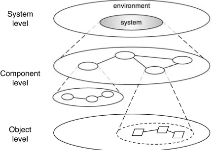
Figure 2. Three abstraction levels of modeling: system level, component level (including multiple sublevels to accommodate a component hier-archy), and object level. A system is realized in terms of components, and each component is realized in terms of objects.
System 1
data flow
:
[system name]:system Environment
A B
[I/O name]
Figure 3. Data flow model of system interaction with its environment.
System 1
[system name]:system Environment
input event / output "write" event
:
[event name] writeX
event
[event name]
:output "read" event readX
Figure 4. Event-based system-level model.
used as units of concurrency by specifying that no two methods of the same object can execute concurrently while any two methods of different objects can.
Modeling complex systems requires using multiple levels of abstraction. We will distinguish the following ab-straction levels: system level, component level (which can include multiple sublevels to accommodate a hierarchy of components), and object level, as depicted in Fig. 2. In our model, we will not try to include all information at each level; instead, the relationship between the layers is one of a gradual refinement of the model where each next level contains more details.
A. System-Level Model
System Environment
Comp. 1 Comp. 2
a
d
Comp. 3
[comp. name] : component
b
internal event (asynchronous) :
[event name]
[event name]
:(synchronous)internal event input/output external event (asynchronous) :
[event name]
[event name]
:external eventoutput (synchronous)
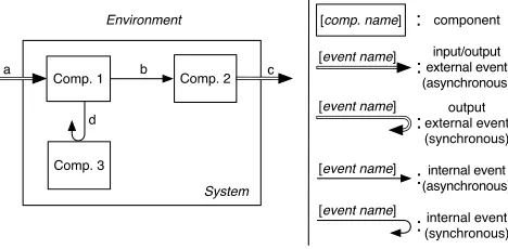
Figure 5. Event-based component-level model.
B. Component-Level Model
At component level, we use components to model the system. A component is defined as an encapsulation of a part of system state and/or hardware resources, with a clearly defined interface and functionality. Importantly, state variables and hardware resources must belong to only one component and cannot be shared by two or more components (the question of allocating CPU resources, i.e. processing time, to components will be addressed later). This definition allows for hardware, software, and mixed hardware/software components.
Each component can be specified independently of the rest of the system in terms of time-constrained reactions to input events. Input events can either be external events originating outside the system, or internal events originat-ing in another component. Both input and output events can be asynchronous (“write” events, one-way interaction) or synchronous (“read” events, synchronization events, etc.). Note, however, that external input events are always asynchronous (Fig. 5). Unlike reactions to asynchronous events, reactions to synchronous events cannot have a permissible execution window of their own, as they have to complete before the deadline for the component that posted the synchronous event and awaits a response.
Components can be organized hierarchically, when a component is partitioned into subcomponents. Partitioning is governed by considerations such as composability, re-usability, ease of understanding, etc. as will be described later in this article.
Application
Comp. 6
Resource platform Comp. 5 Comp. 4
Comp. 3 Comp. 2
Comp. 1 a
b
c
d e f g h
Environment
j i
[comp. name] : component
internal event (asynchronous) :
[event name]
[event name]
:(synchronous)internal event input/output external event (asynchronous) :
[event name]
[event name]
:external eventoutput (synchronous)
Figure 6. Partitioning of a system into a resource platform and a software application.
C. Resource Platform
A useful abstraction that can be built upon system partitioning into components is the notion of a resource
platform. The intuition behind it is that a number of
com-ponents taken together can present a certain basic func-tionality with a clearly defined interface that can be uti-lized by a whole range of applications (Fig. 6). A resource platform typically includes all hardware components of the system, since they are the most difficult to change and may often have somewhat limited composability, but it can equally well include mixed hardware/software components or software-only components that are used as resources by the applications. This gives us a clear separation of the system into a resource platform and an application (embedded systems typically have only one application, but it is possible to consider several applications sharing the same platform at runtime).
Note that since the separation into a platform and an application is performed at a relatively high level of abstraction, a platform may have multiple instances, differing in the choice of specific hardware and/or specific implementation of software. This approach allows for a fast and efficient development of a number of applications for a certain platform while leaving enough flexibility in platform implementation to perform optimizations in device size, cost, power consumption, and performance.
D. Object-Level Model
At the lowest level, each component is modeled using
reactive objects. A reactive object is a model that can
have one or several hardware and/or software instances; however, it cannot be instantiated as a mixed hard-ware/software entity. The choice of implementation is
after t a before tb System
Comp. 1
b a
Comp. 2
Environment
Obj. 1
Obj. 4
Obj. 5
Obj. 3 Obj. 2
Comp. 3
Obj. 6 before t2
[comp. name] : component
[obj. name] : hardwareobject
[obj. name] : softwareobject
asynchronous message : [method name]
:synchronousmessage after ta before tb
[method name] m6
after t1 m3
m2
m4
e m5
internal event (asynchronous) :
[event name]
[event name]
:(synchronous)internal event external event (asynchronous) :
[event name]
[event name]
:external event(synchronous)
d c
f g
m1
Figure 7. Event-based object-level model. For each reaction, a per-missible execution window can be specified using the aftertabefore
made at this level, so an object-level model clearly spec-ifies which objects should be implemented in hardware and which in software (Fig. 7).
Both software and hardware objects react to external and internal input events and for each reaction a permis-sible execution window can be specified relative to the time of the event (Fig. 1). External input events originate in the environment, and each type of event triggers a method of a specific object. Internal input events originate within the system; in the case when such events are both produced and consumed by software objects, they can be viewed and implemented as messages. Even events originating outside the system or in hardware objects can be translated into messages if they are consumed by a software object.
As any events, messages can be either synchronous or asynchronous. In the latter case, a software object can also post a message to itself. Asynchronous messages can be delayed by a certain amount of time defined relative to the baseline of the object sending the message. This also allows to encode a periodic behavior by letting an object post a delayed asynchronous message to itself. Synchronous messages return a value, and the execution of the sender object is blocked until then; that is why reactions to synchronous messages cannot be delayed and always inherit the permissible execution window of the sender.
A software object encapsulates its state and provides methods to operate on it; a reactive software object cannot block during method execution waiting for input. In our model, state protection is absolute – all mutable variables have to be state variables in some object, and no access to state variables is allowed except via methods of the object. Besides, no two methods of the same object are allowed to execute concurrently but methods of two different objects can, resulting in an object-level concurrency model.
III. SOFTWAREDESIGNMETHODOLOGY
Here we present a methodology for embedded software design based on the modeling framework described in the previous section. This framework allows us to model both software and hardware parts of an embedded system, and a complete model of the system is essential for designing embedded software and verification of the system as a whole.
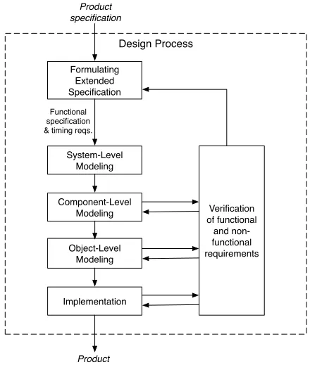
The different stages of the design process are presented in Fig. 8. The input to the design process is the product specification which originates from the client commis-sioning the system and which we assume to be static during the development of the system. This specification is usually written in a natural language, is often incom-plete and imprecise. Hence the first step is drawing up a complete specification with a clear division into func-tional and non-funcfunc-tional parts. In our case, funcfunc-tional specification is integrated with timing requirements and is used throughout system modeling and implementation. Non-functional specification lists the remaining system properties and constraints, such as system size and power
Design Process
Product specification
Formulating Extended Specification
System-Level Modeling
Component-Level Modeling
Object-Level Modeling
Implementation
Verification of functional
and non-functional requirements
Product
Functional specification & timing reqs.
Figure 8. Stages in the design process: from a specification to a ready product.
consumption, and is primarily used during verification. It can also be used to guide selection of ready-made components, especially those including hardware.
The second step is formulating a system-level model where system interface to its environment is defined in terms of external input events triggering time-constrained system reactions and system output events which are part of such reactions. In the third step, this model is elaborated by identifying system components and in-terfaces between them. Such components are key to facilitating software re-use and maintenance, as well as system verification. In the fourth step, the components are realized using reactive objects, and a decision is made on which reactive objects should be implemented in software and which represent models of (existing) hard-ware parts. At every step, the model of each component is matched against a repository of previously developed components (either software or hardware), which should contain reactive models of components alongside their implementation.
on a particular hardware platform is separate from verifi-cation of the model itself.
(1) Defining Extended System Specification
The extended specification has to be complete, verifi-able, and contain a clear separation into functional and non-functional specification; it is obtained by refining the original product specification. Our approach requires that the functional specification should be expressed in terms of time-constrained reactions to external events represent-ing input to the system or changes in the environment. Thus timing requirements are integrated into functional specification. It has to be noted that not all systems let their functionality to be naturally defined in terms of time-constrained reactions, which should be seen as a limitation of applicability of our approach. However, it is our belief that the majority of embedded systems can be specified in such a way.
A prominent example is a system with a time-continuous input; a system which as such does not con-form to the notions of events and reactions. However, on closer inspection, any discrete realization of such a system would indeed require a sampling strategy with its corresponding timing requirements.
In other cases timing requirements can be implicit, defined by the rate of incoming events and the necessity to keep up with them. A typical example is routing of packets in a network; while the maximum forwarding delay may be omitted from the specification, it can be derived from a packet buffer length together with the allowed drop rate for a given traffic profile.
(2) Formulation of System-Level Model
In this step a system-level model should be formulated from the functional and timing specification by determin-ing the system’s boundary with its environment and its interface. To achieve a clear-cut separation between the system and its environment, the system should be defined to encompass all the functionality that we have to develop, and it should be taken to include the hardware that the developed software will execute on. Such hardware should be notionally included in the system even if it is given and cannot be changed during the development process. Note that the environment includes both natural phenomena the system will interact with and the infrastructure that is be-ing developed or has been developed separately. Thus all “external” services used by the system, especially those shared between the system under development and other systems, are considered to be part of the environment rather than the system proper.
(3a) Partitioning into Components
Although component-based design has been studied for several decades, partitioning of a system into components (as well as partitioning of a component into subcompo-nents), remains more of an art than an exact science.
However, it is possible to identify the main guiding principles.
Each component should have a clearly defined role in the system, and a one-to-one mapping between com-ponents and system functions is always preferable. This means that any two independent tasks, triggered by in-dependent external events and resulting in inin-dependent outputs, should be realized by two separate components. The same is true for the case when a system should perform two activities in parallel, with little or no state sharing and/or interaction between them.
A special type of components (often associated with hardware or mixed hardware/software components) are resources which can be used by one or several activi-ties and which usually enforce some kind of exclusion or sharing protocol to guarantee consistency of system output and/or its internal state. Several resources are often bundled together in one component when they are used jointly to perform one task or cannot operate in parallel. Apart from these main principles, a number of other considerations can affect the design of a particular system, such as:
• composability – to facilitate system composition
from newly-designed or ready-made components, it is important for each component to have a clear purpose (role in the system) and a clearly defined interface. It is also advantageous to have as few interdependencies between components as possible.
• reusability – functionality common to a class of
(possible) applications can be effectively assigned to a separate component, facilitating component re-use.
• robustness – to make better use of ready-made
com-ponents, and to enhance system verification while shortening the development time, it is important that each component is designed with regard to future verification (testing, simulation, and possibly formal verification) at component level as well as at system level. Robustness can also be improved if components are used as fault-containment regions, which requires detectability of errors at component boundaries.
• ease of understanding – an extremely important
consideration that is often overlooked is that parti-tioning into components should enhance the ability of the original developer(s) of the system as well as those who may work with it in the future to clearly understand the functions and structure of the system. This calls for the components to be small enough to be easily comprehendable, but at the same time large enough to keep the structure of the higher-level component simple. Experience shows that following this principle leads to fewer mistakes (and hence shorter development times and increased robustness) and facilitates re-use and maintenance.
specification, enhances composability, and facilitates ver-ification of individual components. We therefore strongly discourage synchronous communication across compo-nent boundaries. Synchronous communication between components should normally be used for predictably quick interaction, such as reading a value (as opposed to waiting for a value to be computed), or performing a hardware operation that takes a known time to complete under certain operational conditions.
Once defined and implemented, components can be stored in some repository for future use. It is important to preserve not only the actual implementation, but also a model of the component (see section 3b) alongside its testing and verification results. It may also be useful to preserve a testing suit for a component so that the tests can be re-run in a new setting. If the implementation of a component is protected as intellectual property and will not be accessible for system verification, the timing properties of the component also have to be stored in the repository. These would have to include execution time and maximum blocking time (per hardware resource) for each reaction defined in the interface of the component.
(3b) Search for Ready-Made Components
In this step, models of defined components are matched against models of earlier developed components from the repository. Comparison between the models requires that they are of the same kind. In our case, it means that a component model should have its functionality expressed in terms of time-constrained reactions to events external to the component. Identity of modeling principles should lead to a straightforward integration of a matched component into the system model.
There might be components in the repository that do not match the specification, but can be either adapted by introducing an intermediate layer, or can be modified to fit the specification. The downside of component mod-ification is that it may require substantial work on re-implementing the component as well as invalidate the testing and verification results.
(3c) Hierarchical Refinement of Component Structure
One of the strengths of component-based design is the possibility of hierarchical refinement of component struc-ture. Partitioning of a component into subcomponents closely mirrors partitioning of a system into components as described above; the same principles and guidelines apply. Since one and the same component can (at least theoretically) be used in different systems, partitioning into subcomponents should be performed independently for each component and should not be influenced by a wider context in which the component is used. However, it is possible that identical subcomponents are identified as parts of different components, and those can be viewed as separate instances of the same component class.
If any new subcomponents have been identified in this step, a return to search for matching components in a
repository is warranted. The process is repeated until no further refinement of component structure can be justified.
(4) Realization Using Reactive Objects
The last step in the modeling process is component realization using concurrent reactive objects. This step in-volves partitioning of the component into reactive objects and identifying hardware and software parts. Similarly to partitioning into subcomponents, it is performed on each component independently of its context. Note that at this level hardware parts are modeled as reactive objects, which allows for a certain flexibility when several hardware parts are modeled using the same object model if they only differ in, for example, power consumption.
For each component, it is necessary to identify: hard-ware resources; object state in terms of state variables; and object functionality in terms of methods. Partitioning of a component into objects is governed by slightly different principles than partitioning of a system into components. These principles can be obtained by adaptation of well-known object-orientation strategies to the concept of concurrent reactive objects. The following has to be taken into consideration:
Each object encapsulates its state that can only be accessed by methods of the same object. At the same time, the objects are units of concurrency, meaning that any two methods of the same object cannot be executed concurrently but any two methods of two different objects can. A notable exception is the case when an object posts a synchronous message to another object; then the caller remains blocked until the invoked method returns.
The guiding principles of partitioning into objects aim to maximize schedulability of the system while main-taining state consistency. Component state, seen as a collection of state variables, should be partitioned and assigned to objects in such a way that
• state duplication (when the same state is duplicated as state variables in two or more objects, leading to synchronization problems) is avoided;
• state variables routinely modified together are encap-sulated in one object;
• otherwise, state is maximally distributed between different objects to allow for a better schedulability of the system.
Functionality should be assigned to methods, and meth-ods to objects in such a way that
• methods using the same state variables are assigned to the same object;
• methods using different parts of component state are assigned to different objects together with cor-responding state variables, in order to maximize schedulability of the system; an exception to this rule is the case when consistency between several state variables has to be guaranteed;
any other method while an earlier invoked method is executing. For example, in some cases a single reaction should be split into two methods, one calling the other asynchronously, thus creating a window of opportunity for a reaction with a shorter deadline to execute on the same object in between the two methods.
The issue of software interaction with hardware parts is of utmost importance and has to be considered sepa-rately. This interaction is often governed by complicated protocols that are not relevant to the application at large. Hence it is a good idea to have a single software ob-ject controlling access to specific hardware. Apart from providing a useful abstraction of the software-hardware interface, such objects can be used to explicitly control sharing of the hardware resource by enforcing arbitration or queuing if so required.
(5) Implementation
The next step is the implementation process in which the system model is instantiated. The hardware platform is built using identified hardware parts (COTS compo-nents, SoC blocks, etc.), and software reactive objects are implemented in some programming language. In the case when some of the software components are re-used from the repository, the issue of code integration has to be addressed. The complexity of code integration will depend on the language used in the implementation of the re-used components.
An example of a programming language, Timber, fully supporting the described modeling framework and thus suitable for use together with the present software design methodology, will be described in section IV.
(6) Verification
The final step in embedded system design is verification (see Fig. 8). We will distinguish between verification of the model and verification of the implementation; both should be conducted at component as well as system level. Verification of the model is done against system speci-fication and specispeci-fication of individual components. This includes verification of component composition at system level and verification of functional specification (including timing requirements), which can be performed using simulation or with formal methods (see, for example, the work on UPPAAL [5]–[8]). Importantly, verification of the model is independent of its feasibility, i.e. whether or not it can be implemented in a specific programming language and on a specific hardware platform in such a way that the functional and timing requirements are met. Verification of the implementation should also be con-ducted at both component and system level and, un-like verification of the model, it involves verification of both functional and extra-functional requirements. At component level, it is only necessary to verify that the implementation corresponds to the model. At system level, both component integration and system feasibility
have to be verified. System feasibility refers to the ability of a specific implementation (software and hardware) to meet the functional and timing specifications of the model under extra-functional constraints such as energy consumption; an important part of feasibility verification is schedulability analysis (see [9]). Note that schedula-bility analysis requires a full knowledge of the system implementation. In the case when the implementation of a particular component is not available for analysis, at least the list of resources used by each reaction of the component should be known together with the execution time and maximum blocking time for each resource. Schedulability analysis should be the preferred way of system verification since it allows to prove system correct-ness for all inputs and in all situations, as do other formal methods. However, verification of system implementation can also be conducted using simulation and testing.
Let us separately consider verification of a resource platform. A clear division into a platform and an ap-plication allows to verify them separately, so that an already verified platform with known properties can be used for development of other applications. It should be noted, however, that system-level verification such as schedulability analysis has to be performed on the system as a whole, including both the application and the resource platform, even if the platform has previously been verified.
IV. ANIMPLEMENTATIONAPPROACH: THETIMBERLANGUAGE
The presented model is sufficiently general to allow a variety of possible implementations. For example, since we can model a complete system including both hardware and software parts, the border between hardware and software can be adjusted even after the model has been completed. Hardware components together with hardware parts of mixed (hardware/software) components can be realized by e.g. selecting existing COTS hardware parts and integrating them into a single hardware platform, whereas software components together with software parts of mixed components have to be implemented in some programming language, typically combined with a minimal operating system or a kernel that will provide scheduling, I/O, etc.
the model and its implementation becomes very difficult to verify.
Another possible implementation approach is to use the recently developed modeling and programming language Timber, which targets real-time systems ([10]–[12]). Tim-ber is a high-level programming language that uses the same primitives as the proposed model, including reactive objects and time-contrained reactions. Hence translation of a model into Timber code is straightforward and preserves system structure and timing specification, clos-ing the gap between the model and its implementation. Timber code can be compiled into a subset of C and executed on any target platform in combination with a Timber kernel3, which uses permissible execution win-dows preserved in the code for deadline-based scheduling. Timber is both a high-level programming language for real-time systems and a formalism that can be used to verify a system’s functional behavior, timing properties (complying with deadlines), liveness (absence of dead-locks), and termination of computations. Let us briefly describe the relevant properties of the language:
• inherent support for reactivity: the system
function-ality is expressed in terms of reactions to external events, with reaction defined as a combination of internal state updates and/or system outputs. Each reaction can be comprised by a chain of reactions executed by different objects, some of them executed concurrently. Execution of a system reaction must be non-blocking, i.e. it cannot block waiting for an external input.
• time-constrained reactions: each reaction has a
base-line (the earliest time when execution can start) and a deadline (the latest time by which execution must have finished); it is possible to schedule a reaction to start at some point of time in the future by setting its baseline relative to the baseline of the reaction being executed. The timing requirements are preserved in the application code at run-time and can be used to guide scheduling.
• object-orientation: while constants (including global
functions) can be defined at the top level, mutable variables are only allowed within objects as state variables. State encapsulation and protection are achieved by limiting access to these variables to the methods of the object, and state consistency is easily guaranteed by always enforcing mutual exclusion between the methods of the same object.
• object-level concurrency: Timber is a highly
concur-rent language with concurrency achieved by allowing methods of any two different objects to be executed in parallel.
• message passing between objects: Timber objects
communicate by passing messages, synchronous (when the sender remains locked and waits for the
3A prototype version of a Timber kernel has so far been implemented
for a generic POSIX environment and for an ARM platform, but thanks to its minimalistic nature it can be ported to other platforms relatively easily.
message to return), and asynchronous (when the sender posts a message to another object or to itself, possibly with a postponed baseline, and continues execution). Asynchronous messages lead to concur-rent execution of reactions.
V. ANEXAMPLESYSTEM: A PERSONALALARMDEVICE
The software design methodology described above has been tested in the development of a personal alarm device, used here to demonstrate different stages in the design process. Some details have been omitted for presentation purposes. The following functional specification of the device was given in the beginning of the design process: The personal alarm device is a battery-driven system worn by a person on his or her body, for example, by an elderly person at a care facility. The device is capable of detecting the person’s fall by analyzing acceleration. Once a fall has been detected, a fall alarm is sent wirelessly to an external receiver. The analysis requires that acceler-ation is sampled periodically everytperiod milliseconds. The device also includes an assistance call button that can trigger a separate kind of alarm sent in the same manner. An alarm must be sent withintalarmmilliseconds after a fall has been detected or after the button has been pressed.
(1) Defining Extended System Specification
An extended system specification should include both functional and non-functional requirements. The func-tional requirements have to be expressed in terms of time-constrained reactions. Two such reactions can be identified by analyzing the original specification.
The first reaction is sending an assistance alarm when the push button has been pressed. There is a timing requirement that the alarm is to be sent within talarm milliseconds. The second reaction is sending a fall alarm, which is triggered by fall detection. This is realized using a fall detection algorithm that requires sampling acceler-ation at regular intervals equal to tperiod milliseconds. The algorithm distinguishes two stages in fall detection: impact detection, with impact detected by acceleration exceeding a threshold value; and posture evaluation (see [13], [14] for a detailed description of the algorithm). Posture evaluation is performed tlag milliseconds after an impact has been detected, and is used to establish if the person is lying down, in which case a fall has been detected. The acceleration is sampled with the same peri-odicity both for impact detection and posture evaluation. Hence the following timing requirements can be given for the second reaction: the acceleration sampling period tperiod; the lag between impact detection and posture evaluationtlag; and the maximum period of time between fall detection and sending an alarmtalarm.
AD
[system name]:system Environment
input event / output "write" event :
[event name] transmit
buttonPressed
[event name]
:output "read" event readAcc
reset
Figure 9. System-level model for personal alarm device. Input events:
reset and buttonPressed. Output “read” event: readAcc (reading
accel-eration). Output “write” event: transmit (sending a fall alarm or an assistance alarm).
Non-functional requirements for the system include a relatively small size (since the system has to be worn on the body, for example, at the hip), and a low power consumption (as the device is to be powered by a battery).
(2) Formulation of System-Level Model
Analyzing system specification, we can distinguish two events that the system should react to: an assistance call realized as an interrupt from a button; and the person’s fall. The interrupt from a button can be modeled as an external input event. The person’s fall, however, is something that is detected by the fall detection algorithm which is internal to the system and hence it is not an external event. However, we can encode a periodic sampling of acceleration by the system as a reaction to a reset (an external input event) that starts up the system and triggers a reaction that includes sampling the acceleration (an external output “read” event) and posting a message with a delayed baseline that invokes another sampling after tperiod milliseconds, and so forth.
The timing requirements on the first reaction consist of a relative deadline talarm milliseconds; the timing requirements on the second reaction are defined for each sampling that has a baseline equal to the baseline of the previous sampling plus tperiod milliseconds.
Note that while the hardware for the button, the ac-celerometer, and the radio transceiver are clearly a part of the system, the receiver of the alarm transmission is outside the developer’s remit and should be viewed as an external service, not a system component. Thus the interface between the system and its environment is comprised on one hand, by reset interrupts and call button interrupts, and on the other hand, by the radio protocol used for communicating the alarms alongside the codes used to distinguish an assistance alarm from a fall alarm (see Fig. 9).
(3a) Partitioning into Components
Let us now consider partitioning into components of our device. Analyzing the specification and the system-level model (Fig. 9) we can see that the application will need the following independent resources: an acceleration
sensor, a message sender (containing a radio transceiver),
and a push button. Their independence warrants creating three separate components, each of them including both hardware and software parts (Fig. 10).
Resource platform
Application Environment
Fall detector
Fall alarm sender
Assistance alarm sender
Acceleration sensor
Message sender
Push button sampleAcc
consumeAcc
sendMsg fallAlarm
assistAlarm
transmit buttonPressed reset
readAcc
[comp. name] : component
internal event (asynchronous)
:
[event name]
[event name]
:(synchronous)internal event
input/output external event (asynchronous)
:
[event name]
[event name]
:external eventoutput (synchronous)
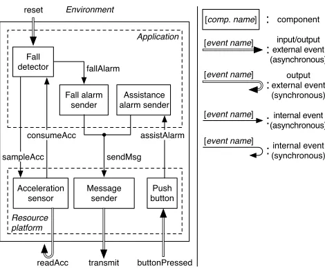
Figure 10. Component-level model for personal alarm device, with separation into a resource platform and a software application.
The next step is to define the interface of these com-ponents, bearing in mind that it should be complete but at the same time sufficiently abstract to accommodate various component implementations, which may possibly use different hardware to support the same functionality. The interface to the acceleration sensor should contain an input that can trigger sampling (sampleAcc), and an output that delivers the acceleration value once it has been acquired (consumeAcc). Note that to preserve reactivity and component independence, we cannot allow the caller to block waiting for the sampling to complete. It is therefore necessary to implement callback functionality in the acceleration sensor to specify to which component the measured acceleration should be delivered. This can be done either when the acceleration sensor is instantiated (a static callback), or by passing a pointer to a function each time sampling is triggered (a dynamic callback). Similarly, to achieve the desired level of generality, the interface of the message sender should only contain one input – sending a message (sendMsg), and one output – delivery of a received message, but the latter is superfluous for our application. Note that the message sender represents a clear example of a shared resource – it can be used by any of the independent tasks of (a) fall detection, and (b) handling an assistance call. As such, it will have to include either message queuing or some kind of arbitration to synchronize access to the resource transparently to the components that may want to use it simultaneously. The interface of the last resource component – the button – is very simple, as it only needs one output to deliver the button event and the target component can easily be set statically. These three components naturally form a platform with clearly defined functionality and interface between it and any possible application.
call handling, resulting in two separate components. At
the same time, it is appropriate to de-couple the fall detection algorithm from how the system should react to a detected fall. For our application, this involves creating a message and forwarding it to the message sender, which can be done by a separate component – a fall alarm sender. If assistance call detection in the application is similarly de-coupled from the reaction to it, we will have two very similar components – a fall alarm sender and an assistance call sender. A possible implementation is to create them as two instances of the same component, a general alarm sender, with some parameter set to different values at initialization. Alternatively, they can be viewed as two different components.
Timing requirements can be part of component spec-ification as time constraints on the reactions. In this case, however, we skip this step and define the timing requirements directly at the object level.
(3b) Search for Ready-Made Components
In our example, the personal alarm device is developed from scratch and there are no components that can be re-used in the design. However, let us consider what compo-nents could be used in the future in similar applications. The first candidate for future use is, of course, the platform, consisting of an acceleration sensor, a message sender, and a push button (all components combining hardware and software). This is most natural because a platform is always defined as a collection of hardware and software resources that can be used by a range of possible applications. At the same time, it is not inconceivable that such components as an acceleration sensor, a message sender, or an alarm sender can be used separately in other designs.
(3c) Hierarchical refinement of Component Structure
In the case of the example system, there is no room for hierarchical refinement of component structure due to the system’s simplicity.
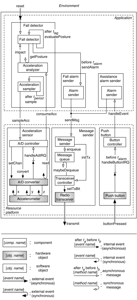
(4) Realization Using Reactive Objects
The object-level model of the example system is pre-sented in Fig. 11. The hardware parts have been identified and are shaded in the figure (their interfaces have been significantly simplified for presentation purposes).
It is clear that all resource components in our example require a mixed hardware/software implementation. In the acceleration sensor, the A/D controller object is used to abstract from the specific hardware interface of the A/D converter and to perform deserialization4. In the message sender, several objects are used to implement the network protocol, and a transparent sharing of the message sender between multiple components is provided by queuing
4Deserialization is required since A/D conversion can only be
per-formed on one channel at a time, but values from all three channels are sent to the application for analysis.
Resource platform
Acceleration sensor
Message sender
Push button
Application Environment
Assistance alarm sender
Button controller
transmit buttonPressed
reset
Alarm sender Fall alarm
sender
Alarm sender Fall detector
Fall detector
Acceleration analyzer
Acceleration sampler impact
getPosture
sampleAcc
A/D controller
A/D converter
Accelerometer
Message queue
Transceiver controller
Push button Radio
transceiver setTxBit consumeAcc
before talarm sendAlarm evaluatePosture
after tlag
sample after tperiod
setChan
convert
[comp. name] : component
[obj. name] : hardwareobject
[obj. name] software object :
z y x
asynchronous message : [method name]
:synchronousmessage after ta before tb
[method name]
internal event (asynchronous) :
[event name]
[event name]
:(synchronous)internal event
external event (asynchronous) :
[event name]
[event name]
:external event(synchronous) read
after ta before tb maybeDequeue
handleButtonIRQ before talarm Message
sender
initTx enqueue handleAdIRQ
sendMsg
handleEvent
Figure 11. Object-level model for personal alarm device. Note the absence of the output “read” event readAcc, which has been redefined as three internal events x, y, z reading different channels of an analog accelerometer.
incoming messages before sending. In the push button, a button controller functions as a simple interrupt handler. The only purely software component that consists of more than one reactive object is the fall detector. The acceleration sampler object triggers sampling by posting an asynchronous message to the sampleAcc method of the acceleration sensor component. Sampling at pre-determined intervals is achieved by the acceleration sam-ple posting an asynchronous message to its own method
currentBaseline+tperiod.
The acceleration analyzer and fall detector objects cooperate to detect a fall. The acceleration analyzer posts an asynchronous message to the fall detector on detection of impact upon which the fall detector updates its internal state and posts an asynchronous message to its own method evaluatePosture delayed bytlag. Once the
evaluatePosture method is invoked, the person’s posture
is requested from the acceleration analyzer and if he or she is lying down, the fall detector posts an asynchronous message to the fall alarm sender specifying talarm as deadline.
Assistance alarms are handled in a similar way. The application’s handleEvent method is directly linked to the sendAlarm method in the assistance alarm sender. This method inherits the permissible execution window defined for the handleButtonIRQ method in the push button component.
(5) Implementation in Timber
The software part of the system was implemented in the programming language Timber (see section IV). As expected, the system structure presented in the model was complete and did not require any modifications; each reactive object in the model was implemented as such in Timber. Thus parallelism between system reactions was expressed at the object level in the model and preserved in the implementation. The implementation stage also involved writing Timber code for each method. All al-gorithms and functions were implemented; for example, a buffer holding sampled acceleration values was defined as a state variable in one of the objects, and a function was defined for filtering accelerometer data to remove noise in the signal.
The hardware platform defined in the model has not been implemented as yet. However, the software can be executed on any hardware platform that matches the presented model of the system, and we have verified that there exist COTS hardware parts that correspond to each reactive object in the model that should be implemented in hardware (acceleration sensor, radio transceiver, etc.).
(6) Verification
The Timber implementation of the system software was verified, partly by typechecking performed by the Timber compiler, and partly by simulation of the software in a Simulink-based Timber simulator. In the simulated environment, the functionality and the timing specification (preserved in the Timber code of the implementation) were tested by feeding the software simulation with real sensor data of recorded falls of several human subjects as well as their normal daily activity [14].
When software is executed in a simulated environment and not on a real hardware platform, no meaningful execution times are available. However, since the timing specification is preserved in the implementation in form of permissible execution windows for each reaction, it is
possible in the simulation to choose any point within this window, which is correct in the sense that it corresponds to the timing behavior as expressed in the model. A natural choice is to let each reaction to execute (with zero execution time) at its baseline; this approach was used in our simulations. Note that verification of whether the worst-case execution times on a particular hardware platform allow the system to always meet the required deadlines is a separate issue and has not been part of the verification performed so far.
The verification of the software implementation demon-strated the validity of both the algorithm and its imple-mentation, as the falls of the subjects were accurately detected in the simulation.
A detailed account of implementation and verification of the system will be published elsewhere.
VI. RELATEDWORK
The modeling and implementation approach realized in the Timber language can be compared to other solu-tions such as real-time synchronous languages (Esterel, SCADE, Lustre, etc. [15]) and time-triggered languages such as Giotto [16]. However, they are substantially different even if they can be seen as addressing the same design problems. For example, in synchronous languages, concurrency in system behavior is eliminated in the course of implementation, leading to a further separation between specification and model on one hand and implementation on the other hand. In Giotto, software is defined in terms of periodically executed tasks, reading inputs and writing outputs at pre-determined times, which is not particularly suitable for many embedded systems that exhibit a clearly reactive behavior and is not applicable to modeling hardware.
Our design approach is also different from that devel-oped in the Ptolemy project [17]. The Ptolemy approach is a framework for assembly of concurrent components particularly suitable for modeling distributed systems. Essential to it is the notion of an actor, embodying the concept of active objects (as opposed to reactive objects). It can also be argued that the Ptolemy approach does little to bridge the gap between models and implementation, which is achieved in Timber by using executable models. Component-based approach to design of (not neces-sarily embedded) real-time systems has been promoted by various extensions of real-time UML profile [18], with a number of tools already on the market (the most well-known probably are Rhapsody [19], ARTISAN Studio [20], and Rose-RT [21]). However, these solutions do not feature a true integration of timing requirements into functional specification, and do not completely solve the problem of modeling of mixed hardware/software systems.
hardware platform and hardware-software middleware (an API platform), and a software application that is devel-oped for a given system platform. This can be contrasted with our approach where both a resource platform and a software application can be composed of multiple com-ponents, and where a resource platform can be designed together with an application; even if a platform is given, a model of the whole system is used to develop the software application. Our definition of a resource platform includes not only hardware components, but also software and mixed hardware/software components that can be utilized as resources by a range of applications.
VII. CONCLUSION
The presented modeling framework allows for a uni-fied, consistent modeling of both hardware and software. Integration of these models is beneficial for development of embedded systems as they often exhibit a great de-gree of interdependency between hardware and software, and the specification often describes the system as a whole rather than only its software part. At the same time, inclusion of timing requirements in a functional specification in the form of time-constrained reactions allows us to specify, reason about, and verify real-time properties of embedded systems. Moreover, our model-ing framework enables the developer to offer platform-independent correctness/quality of service guarantees for hard/soft real-time systems, provided that the software can be scheduled on a given hardware platform so that all reaction deadlines are met.
By combining this modeling framework with component-based design techniques and by expressing system functionality using reactive objects, our approach draws from the strengths of component-based design as well as from event-based, reactive, concurrent, object-oriented programming models. It facilitates software re-use and maintenance as well as separate development of parts of the system. This approach is realized in the concrete software design methodology presented above.
Apart from addressing the issues of software complex-ity, interdependency between software and hardware, and complying with the timing requirements, our approach also allows to clearly define the notion of a resource
platform as a combination of hardware and software
resources. A resource platform can be designed to serve as a base for a whole range of related applications, decreasing the overall development costs and time to market.
The presented software design methodology can be used both in the case when software is developed along-side a hardware platform (the latter being assembled from existing hardware parts) and in the case when such a platform is given from the start. In both cases, a platform is instantiated using some implementations of hardware and/or software components depending on performance, power consumption, and other non-functional require-ments.
The design approach presented in this article requires further development in the following directions: formal-ization of component structure; creating design tools supporting the methodology; and investigating the role of other requirements, such as power consumption, in the design process. The power consumption issue is espe-cially challenging since it introduces new constraints and modeling parameters to deal with. However, with today’s rapid increase of battery-powered embedded systems, this is a very important issue to address. A holistic view of both timing and and power consumption will offer new and interesting possibilities in the area of embedded system design.
ACKNOWLEDGMENT
This work was supported in part by the Knowledge Foundation in Sweden under a research grant for the project SAVE-IT, the EU SOCRADES project, and the EU Interreg III A North Programme grant 304-13723-2005.
REFERENCES
[1] B. Bouyssounouse and J. Sifakis, Embedded Systems
De-sign: The ARTIST Roadmap for Research and Develop-ment, ser. Lecture Notes in Computer Science. Berlin, Germany: Springer-Verlag, 2005.
[2] C. Atkinson, C. Bunse, H.-G. Gross, and C. Peper,
Component-Based Software Development for Embedded Systems: An Overview of Current Research Trends, ser.
Lecture Notes in Computer Science. Berlin, Germany: Springer-Verlag, 2005.
[3] J. Nordlander, M. P. Jones, M. Carlsson, and J. Jonsson. (2005) Programming with time-constrained reactions. [On-line]. Available: http://pure.ltu.se/ws/fbspretrieve/441200 [4] J. Nordlander, M. P. Jones, M. Carlsson, R. B. Kieburtz,
and A. Black, “Reactive objects,” in Fifth IEEE
Inter-national Symp. on Object-Oriented Real-Time Distributed Computing, 2002, pp. 155–158.
[5] W. Yi, P. Pettersson, and M. Daniels, “Automatic verifi-cation of real-time communicating systems by constraint-solving,” in Proc. of the 7th International Conference on
Formal Description Techniques, 1994, pp. 223–238.
[6] K. G. Larsen, P. Pettersson, and W. Yi, “Model-Checking for Real-Time Systems,” in Proc. of Fundamentals of
Com-putation Theory, ser. Lecture Notes in Computer Science,
no. 965, 1995, pp. 62–88.
[7] J. Bengtsson, K. Larsen, F. Larsson, P. Pettersson, and W. Yi, “Uppaal—a tool suite for automatic verification of real-time systems,” in Proc. of the DIMACS/SYCON
workshop on Hybrid systems III : verification and control.
New York, USA: Springer-Verlag, 1996, pp. 232–243. [8] T. Amnell, et al., “Uppaal - now, next, and future,” in Proc.
of the 4th Summer School on Modeling and Verification of Parallel Processes. London, UK: Springer-Verlag, 2001, pp. 99–124.
[9] L. Sha, et al., “Real-time scheduling theory: A historical perspective,” Real-Time Systems, 2004.
[10] P. Lindgren, J. Nordlander, L. Svensson, and J. Eriksson. (2005) Time for timber. [Online]. Available: http: //pure.ltu.se/ws/fbspretrieve/299960
[11] M. Carlsson, J. Nordlander, and D. Kieburtz, “The seman-tic layers of timber,” in First Asian Symp. on Programming
Languages and Systems: APLAS, ser. Lecture Notes in
[12] The Timber language homepage. [Online]. Available: http://www.timber-lang.org
[13] M. Kangas, J. Wiklander, I. Vikman, L. Nyberg, P. Lind-gren, and T. J¨ams¨a, “Sensorband fall detector prototype: Validation through data collection and analysis,” in The
2:nd Int. Symp. on Medical Information and Communica-tion Technology (ISMICT’07), 2007.
[14] M. Kangas, I. Vikman, J. Wiklander, P. Lindgren, L. Ny-berg, and T. J¨ams¨a, “Sensitivity and specificity of fall de-tection in people aged 40 years and over,” Gait & Posture, 2009, In press.
[15] A. Benveniste and G. Berry, “The synchronous approach to reactive and real-time systems,” Proc. IEEE, vol. 79, no. 9, pp. 1270–1282, 1991.
[16] T. Henzinger, B. Horowitz, and C. Kirsch, “Giotto: A time-triggered language for embedded programming,” Proc.
IEEE, vol. 91, no. 1, pp. 84–99, 2003.
[17] Y. Zhao, J. Liu, and E. Lee, “A programming model for time-synchronized distributed real-time systems,” 13th
IEEE Real-Time and Embedded Technology and Applica-tions Symposium: RTAS, pp. 259–268, 2007.
[18] S. Graf, I. Ober, and I. Ober, “A real-time profile for UML,” Int. J. on Software Tools for Technology Transfer, vol. 8, no. 2, pp. 113–127, 2006.
[19] E. Gery, D. Harel, and E. Palatshy, “Rhapsody: A complete life-cycle model-based development system,” in The Third
Int. Conf. on Integrated Formal Methods, 2002, pp. 1–10.
[20] Artisan Software Tools. [Online]. Available: http://www. artisansw.com/
[21] Rational Rose Technical Developer. [Online]. Available: http://www.ibm.com/software/rational
[22] A. Sangiovanni-Vincentelli, “Defining platform-based de-sign,” EEDesign of EETimes, 2002.
Jimmie Wiklander is a Ph.D. student in Computer Science at Lule˚a University of Technology. He is also a student with SAVE-IT industrial graduate school, which focuses on real-time and safety-critical systems. His research area is component-based design of embedded real-time systems.
Jens Eliasson is an assistant professor in Computer Science at Lule˚a University of Technology and holds a Ph.D. in Industrial Electronics from the same university. His main research areas are low-power design of Embedded Internet Systems (EIS) and wireless sensor networks.
Andrey Kruglyak is a Ph.D. student in Computer Science at Lule˚a University of Technology, Sweden. His research interests include component-based design of real-time systems, object-oriented programming and programming language design.
Per Lindgren holds the position of chaired professor in Embed-ded Systems at Lule˚a University of Technology. He is currently heading a group of Ph.D. students in the area of embedded system design, with a focus on real-time, low-power software and hardware architectures for Embedded Internet Systems. He is a member of the ARTES++ reference group, and member of the ARTEMIS Architecture group, having contributed to the ARTEMIS Strategic Research Agenda.